This article has multiple issues. Please help improve it or discuss these issues on the talk page. (Learn how and when to remove these template messages)
|
Rotary friction welding (RFW) one of the methods of friction welding, the classic way of which uses the work of friction to create a not separable weld. Typically one welded element is rotated relative to the other and to the forge (pressed down by axial force). The heating of the material is caused by friction work and creates a permanent connection. In this method, the materials to be welded can be the same, dissimilar, or composite[1] and non-metallic materials. The friction welding methods of are often considered as solid-state welding.
History edit


Some applications and patents connected with friction welding date back to the turn of the 20th century,[4] and rotary friction welding is the oldest of these methods.[5] W. Richter patented the method of the linear friction welding (LFW) process in 1924 in England and 1929 in the Weimar Republic; however, the description of the process was vague[5] and H. Klopstock patented the same process in the Soviet Union in 1924.[6] But the first description and experiments related to rotary friction welding took place in the Soviet Union in 1956,[4][6] by a machinist named A. J. Chdikov (А. И. Чудиков[3]), who after researching a myriad of scientific studies, suggested the use of this welding method as a commercial process.[6] At first he discovered the method by accident in the Elbrussky mine where he worked: Chdikov did not pay enough attention to lubricating the lathe chuck's insides and then learned he had welded the workpiece to the lathe.[3] He wondered if this accident could be used for joining and came to conclusion that it was necessary to work at high rotation speeds (as of 2023[update] about 1000 revolutions per second), immediately brake and press down welded components.[3] He decided to write a letter to the Ministry of Metallurgy and received the answer that this welding was inappropriate, but short notes about the method were published in the newspapers of the Union, arousing interest from Yu. Ya. Terentyeva who was manager of the national Scientific Research Institute of Electrical Welding Equipment, and with time Chdikov's method was disseminated.[3] The process was introduced to the United States in 1960.[4] The American companies Caterpillar Tractor Company (Caterpillar - CAT), Rockwell International, and American Manufacturing Foundry all developed machines for this process. Patents were also issued throughout Europe and the former Soviet Union. The first studies of friction welding in England were carried out by the Welding Institute in 1961.[6] The US through Caterpillar Tractor Company and MTI developed an inertia process in 1962.[4][6] Europe through KUKA AG and Thompson launched rotary friction welding for industrial applications in 1966, developed a direct-drive process and in 1974 built the rRS6 double spindle machine for heavy truck axles.[7][8]
newIn 1997, an international patent application was filed, entitled "Method of Friction Welding Tubular Members". Inventor A. Graham demonstrated, on welding pipes with a diameter of 152.4 mm, a method that uses radial friction welding with an intermediate ring for connecting long pipes,[9][10] at long last succeeding after some attempts occurred in 1975,[11] and after scientists in Leningrad theorized on the idea in newspapers.[3] Another method was invented and experimentally proven at The Welding Institute (TWI) in the UK and patented in 1991, called the friction stir welding (FSW) process.[12] In 2008 KUKA AG developed the SRS 1000 rotary friction welding machine with a forging force of 1000 tons.[7] An improved modification is Low Force Friction Welding, a hybrid technology developed by EWI and Manufacturing Technology Inc. (MTI). The process can apply to both linear and rotary friction welding.[13] As of 2020[update] KUKA has been operating in 44 countries and has built more than 1200 systems,[7][14] including for subcontract facilities;[15]

However, there are more companies in the world with experience; for example, The Welding Institute TWI has more than 50 years of expertise and insight inherent to process development.[16] As of 2023[update], with the help of more and more companies, friction welding has become popular worldwide with various materials both in scientific studies and industrial applications.[citation needed]
Applications edit
Rotary friction welding is widely implemented across the manufacturing sector and has been used for numerous applications,[17][18][19] including:
- Parts in gas turbine such as: turbine shafts, turbine discs, compressor drums,[20]
- Automotive parts including steel truck axles[21] and casings, overhead valve engine,[22] motor hollow pistons, passenger car wheel rims, converter for passenger car automatic gears, drive shafts,[23] yoke shaft[24]
- Turbine for aircraft engine,[25]
- Monel to steel marine fittings,
- Piston rods,
- Copper - aluminium electrical connections,
- Heat exchangers,
- Cutting tools for example for lengthening drill bits,[26]
- Drill pipes,[27]
- Reactor pressure vassels nozzles,[20][28]
- Tubular transition joints combining dissimilar metals (Aluminium - Titanium and Aluminium - Stainless steel),
- Potential for medical applications,[29][30]
- For learning students at technical universities.
Connections geometry edit

Rotary Friction Welding can join a wide range of part geometries Typically: Tube to Tube, Tube to Plate, Tube to Bar, Tube to Disk, Bar to Bar, Bar to Plate and in addition, to this a rotating ring is used to connect long components.[32]

Geometry of the component surface not is not always flat for example it can be conical surface and not only.[33]
Types of materials to be welded edit
Rotary friction welding enables to weld various materials.

Metallic materials of the same name or dissimilar either composite,[1] superalloys[34] and non-metallic e.g. thermoplastic polymers[35] can be welded and even welding of wood is investigated,[36] however welding a wood is not a good idea. Weldability tables of metallic alloy can be found on the Internet and in books.[31]

Sometimes an interlayer is used to connect non-compatible materials.[29][37]

Rotary friction welding for plastics edit
Friction welding is also used to join thermoplastic components.[35]
Division due to drive motor edit
In direct-drive friction welding (also called continuous drive friction welding) the drive motor and chuck are connected. The drive motor is continually driving the chuck during the heating stages. Usually, a clutch is used to disconnect the drive motor from the chuck, and a brake is then used to stop the chuck.
In inertia friction welding the drive motor is disengaged, and the workpieces are forced together by a friction welding force. The kinetic energy stored in the rotating flywheel is dissipated as heat at the weld interface as the flywheel speed decreases. Before welding, one of the workpieces is attached to the rotary chuck along with a flywheel of a given weight. The piece is then spun up to a high rate of rotation to store the required energy in the flywheel. Once spinning at the proper speed, the motor is removed and the pieces forced together under pressure. The force is kept on the pieces after the spinning stops to allow the weld to "set".[32]
Stages of process edit

- Step 1 and 2, friction stage: one of the component is set in rotation, and then pressed to the other stationary one in axial of rotation,
- Step 3, braking stage: the rotating component is stopped in braking time,
- Step 4, upsetting stage: the welded elements are still forging by forge pressure (pressed down),
- Step 5: in standard RFW welding (standard parameters), a flash will be created. Outside flash can be cut off on the welder.[38]

However, referring to the stages chart:
- modifications of the process exist,

Chart comparison in several friction welding methods.An overview of the charts can be found on the MTI website.[43][44] - may depend on the version of the process: direct-drive, inertia friction welding, hybrid welding,[20]
- there are many versions of welding machines,
- many materials can are welded with not the same properties, with various geometries,
- the real life process does not have to match to the ideal settings on the welding machine.

RFW Friction work on cylindrical rods workpieces edit
This section needs expansion. You can help by adding to it. (December 2020) |
Friction work create weld and can believe that is calculated for cylindrical workpieces from math:
Work:
(1)

Moment of force M general formula:
(2)

The force F will be the frictional force T (F=T) so substituting for the formula (2):
(3)

The friction force T will be the pressure F times by the friction coefficient μ:
(4)

So moment of force M:
(5)

The alpha angle that each point will move with the axis of rotating cylindrical workpieces will be:
(6)

So friction work:
(7) [verification needed]

For variable value μ over friction time:
(8)

This requires verification but from equation it appears that turnover and force (or pressure no surface ) is linear to friction work (W) so for example if pressure increase 2 times then friction work also increase 2 times, if turnover increase 2 times then friction work also increase 2 times and referring to rules conservation of energy this can heat 2 times more the material to the same temperature or the temperature may increase 2 times. However pressure has the same effect over the entire surface but rotation have more impact away from the axis of rotation because it is a rotary motion. Referring to thermal conductivity the friction time affects to the flash size when shorter time was used then friction work is more concentrated in a smaller area.[verification needed]

or variable values μ, n, F over friction time:
(9) [verification needed]

- t [s]- time of friction (when piece rotary),
- μ - coefficient of friction,
- F [N]- pressure force,
- r [m]- radius of workpiece,
- n [1/s] - turnover per second,
- W [J] - friction work.

Therefore, the calculation in this way is not reliable in real is complicated. An example article considering the variable depends on the temperature coefficient of friction steel - aluminum Al60611 - Alumina is described by authors from Malaysia in for example this paper "Evaluation of Properties and FEM Model of the Friction Welded Mild Steel-Al6061-Alumina"[45] and based on this position someone created no step by step but whatever an instructional simulation video in abaqus software and in this paper is possible to find the selection of the mesh type in the simulation described by the authors and there are some instructions such as use the Johnson-Cook material model choice, and not only, there is dissipation coefficient value, friction welding condition, the article included too the physical formulas related to rotary friction welding described by the authors such as: heat transfer equation and convection in rods, equations related to deformation processes.[45] Article included information on the parameters of authors research, but it is not a step by step and simple instruction such as also the video and good add that it is not the only one position in literature. The conclusion include information that: "Even though the FE model proposed in this study cannot replace a more accurate analysis, it does provide guidance in weld parameter development and enhances understanding of the friction welding process, thus reducing costly and time consuming experimental approaches."[45]
The coefficient of friction changes with temperature and there are a number of factors internal friction (viscosity - e.g. Dynamic viscosity according to Carreau's fluid law[46]), forge, properties of the material during welding are variable, also there is plastic deformation.
Carreau's fluid law:
Generalized Newtonian fluid where viscosity, , depends upon the shear rate, , by the following equation:


(10)

Where:
- , , and are material coefficients.
- = viscosity at zero shear rate (Pa.s)
- = viscosity at infinite shear rate (Pa.s)
- = relaxation time (s)
- = power index


Modelling of the frictional heat generated within the RFW process can be realized as a function of conducted frictional work and its dissipation coefficient, incremental frictional work of a node 𝑖 on the contacting surface can be described as a function of its axial distance from the rotation centre, current frictional shear stress, rotational speed and incremental time.[47] The dissipation coefficient 𝛽FR is often set to 0.9 meaning that 90% of frictional work is dissipated into heat.[47]
(11) 𝑑𝑞FR(𝑖) = 𝛽FR ∙ 𝑑𝑊FR(𝑖) = 𝛽FR ∙ 𝜏𝑅(𝑖) ∙ 𝜔 ∙ 𝑟𝑖 ∙ 𝑑𝑡 on contacting surface of node 𝑖[47]
- 𝛽FR - dissipation coefficient,
- 𝑊FR - frictional work,
- 𝑟𝑖 - distance from the rotation centre,
- dt - time increment,
- 𝜏𝑅(𝑖) - current frictional shear stress,
- 𝜔 - rotational speed.
Friction work can also calculate from power of used for welding and friction time (will not be greater than the friction time multiply to the power of the welder - engine of the welder) referring to rules conservation of energy. This calculation looks the simplest.
(12) E = Pxt or for not constant power

- E - energy,
- P - power,
- t - power runtime.
However, in this case, energy can be also stored in the flywheel if is used depending on the welder construction.
General flywheel energy formula:
(13)

where:
- is the stored kinetic energy,
- ω is the angular velocity, and
- is the moment of inertia of the flywheel about its axis of symmetry.


Sample calculations not by computer simulation also exist in the literature for example related to power input and temperature distribution can be found in the script from 1974:
K. K. Wang and Wen Lin from Cornell University in "Flywheel friction welding research" manually calculates welding process and even at this time the weld structure was analysed.[4]
However, generally: The calculations can be complicated.
Weld Zone Description edit
Weld photo gallery edit
 |
 |
 |
|---|---|---|
 |
 |
 |
 |
Heat and mechanical affected zones edit
Friction work is converted into rise of temperature in the welding zone area, and as a result of this the weld structure is changed. In typical rotary friction welding process rise of temperature at the beginning of process should be more extensively away from the axis of rotation[31] because points away axis have greater linear velocity and in time of weld the temperature disperses according to thermal conductivity welded parts.

"Technically the WCZ and the TMAZ are both "thermo-mechanically affected zones" but due to the vastly different microstructures they possess they are often considered separately. The WCZ experiences significant dynamic recrystallisation (DRX), the TMAZ does not. The material in HAZ is not deformed mechanically but is affected by the heat. The region from one TMAZ/HAZ boundary to the other is often referred to as the "TMAZ thickness" or the plastically affected zone (PAZ). For the remainder of this article this region will be referred to as the PAZ."[52]
Zones:
- WCZ– weld center zone,
- HAZ – heat affected zone,
- TMAZ – Thermo-Mechanically Affected Zone,
- BM – base material, parent material,
- Flash.
Furthermore, in the literature, there is also a subdivided according to the type of grain.[53]
Similar terms exist in welding.
During typical welding initially, the outer region heats up more, due to the higher linear velocity.

Next, the heat spreads, and the material is pushed outside, thus creating an outside flash which can be cut off on the welding machine.

Heat flow, heat flux in rods edit
This section needs expansion. You can help by adding to it. (December 2020) |
It can create a hypothesis that heat flows in welding time like in a cylindrical rod it makes possible to suppose to calculate a temperature in individual places and times from the knowing of the issues of heat flow and heat flux in rods for example, temperature can be read by using thermocouples and compare with computer simulation.
-
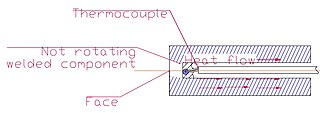 Heat flow in Rod, and variant 1 placement of thermocouple.
 -
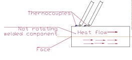 Heat flow in Rod, and variant 2 placement of thermocouples.


Weld measuring system edit
To provide knowledge about the process, monitoring systems are often used and this are carried out in several ways which affects the accuracy and the list of measured parameters.[54]

The list of measured and calculated parameters can looks like this:
- axial force and pressure,
- angular - rotation speed,
- spindle centre,
- velocity,
- vibration,
- length (burn off rate),
- temperature.
Temperature measuring systems edit
Examples of weld measurements. In the literature, can be found measurements of the thermal weld area with thermocouples[55][56] and not only the non-contact thermographic[56][57] method is also used.

However, it also depends on the specific case for a very small area of the weld and HAZ there are cans by difficulties in thermal measuring in real time[citation needed] it can be calculated later after friction time there is heat flow.[citation needed]

Sample source code for temperature measurement made on arduino, this is far away from the topic, however there are missing full open friction welding codes. Exists the free open source software for simulation (List of finite element software) but there is no welding open codes and detailed instructions to this software.
Example in Arduino IDE for temperature measurement with MAX31855. However, the DAQ thermocouple measurement system may have a chip from any manufacturer.


#include "Adafruit_MAX31855.h"

int DO = 11;
int CS = 12;
int CLK = 13;

Adafruit_MAX31855 thermocouple(CLK, CS, DO);

void setup() {
    Serial.begin(9600);
    delay(200);
}

void loop() {
    Serial.println(thermocouple.readCelsius());
    delay(15);
}
Research, temperature, parameters in the rotary friction welding process edit
Quality requirements of welded joints depend on the form of application, e.g. in the space or fly industry weld errors are not allowed.[58] Science tries to gets good quality welds, also some people[59] have been interested in many years in welding knowledge, so there are many scientific articles describing the methods of joining, for example Bannari Amman Institute of Technology, published in 2019 year a literature review in their paper is possible to find out list of people who are interested in friction welding, however in this list not all off people are mentioned for example there is not mentioned about mti youtube channel also there are not written about low force friction welding additionally, the list of people may change over time.
They are performed weld tests which give knowledge about mechanical properties of material in welded zone e.g. hardness tests,[60][48][55] and tensile tests are performed.[48] Based on the tensile tests the stretch curve are created which can give directly knowledge about ultimate tensile strength, breaking strength, maximum elongation and reduction in area and from these measurements the Young's modulus, Poisson's ratio, yield strength, and strain-hardening characteristics is created.

Where, the articles often contain only data related to tensile tests such as:
Where the units of SI are: K, kg, N, m, s and then Pa and this knowledge about this is needed for introducing data, material properties and not do errors in simulation programs.
The units are dependent on the unit system selected. For example, SI unit system:
- Dimensions - m
- Mass Density in kg/m3
- Young's modulus - Pa
- Poissons’s ratio - empty
- Thermal conductivity - W/m*K
- Specific heat - J/Kg*K
- Pressure - Pa
-
 Unit system
 -
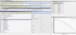 Ansys sample Print Screen 316 Stainless Steel Properties with temperature.
 -


Research articles also often contain information about:
- chemical composition of connected components
and inclusion process parameters is obvious such as:
- Friction Pressure (MPa)
- Friction Time (s)
- Welding Speed (rpm)
- Upset Pressure (MPa)
- Upset Time (s)
Is also possible to find descriptions in research literature about: mechanical properties, microstructure, corrosion and wear resistance, and even cytotoxicity[30] welded material.
However, why research connect topic of cytotoxicity to welding if it is a subject not closely related (cytotoxicity[30] is the quality of being toxic to cells). On this article can write that exist same off toxic metals and metals vapors such as polonium. It can be written than in some cases when welding at high temperatures, harmful metal vapors are released and then protection is recommended such as access to fresh air and exhaust these vapors to outside.

There are several methods to determine the quality of a weld[20] and for example the weld microstructure is examined by optical microscopy[48][55][56] and scanning electron microscopy.[61][55][56][48]
The computer finite element method (FEM) is used to predict the shape of the flash and interface, not only for rotary friction welding (RFW),[57] but also for friction stir welding (FSW),[62][63] linear friction welding (LFW),[52] FRIEX.[11]

In addition to the weld testing, the weld heat-affected zones are described.[52] Knowledge of the maximum temperatures in the welding process make it possible to define the area structural changes.[58] Process are analisis e.g. temperature measurements are also carried out for scientific purposes research materials, journals, by use contact thermocouples[55][56] or sometimes no contact thermography[57][56] methods. For example, an ultra fine grain structure of alloy or metal which is obtained by techniques such as severe plastic deformation[64][65] or Powder metallurgy is desirable, and not changed by the high temperature, a large heat affected zone is unnecessary. Temperature may reduce material properties because dynamic recrystallization will occur, there may be changes in grain size and phase transformations[66] structures of welded materials. In steel between austenite, ferrite, pearlite, bainite, cementite, martensite.
Various parameters of welding are tested. The setting of the completely different parameters can obtain different weld for example the structure changes will not be the same width. It is possible to obtain a smaller heat-affected zone (HAZ) and a plastically affected zone (PAZ). The width of the weld is smaller. The results are for example not the same in welds made for the European Space Agency with a high turnover ω = 14000 rpm[61] or another example from Warsaw technical university 12000 rpm[41] and no typical very short friction time only 60 milliseconds[42] instead of using an standard parameters, in addition, in this case, ultra fine grain alloy was welded, but for this example the welded rod workpiece was only 6mm in diameter so it is small rod friction welding[42] another close to this examples with short friction time only e.g. 40 ms also exist in literature but also for small diameter.[60][1] Unfortunately, welding in very short time carries the risk of welding imperfections such as weld discontinuities.
 |
 |
|---|
Some cases of welding are made only individually or only in research such as: The welds created in with specific parameters such as welding time below 100 ms,[42][41] with an appropriate front surface for example (conical contact surface),[67] with materials that are difficult to weld (tungsten to steel),[68] these are not always serial production.
The rotations in the research literature for small diameters can be more as standard even e.g. 25000 rpm.[69] Unfortunately the diameter of the workpiece can be a limitation to the use of high speeds of rotation.
The key points to understand is that: Fine grain of the welded metal material according to Hall-Petch relation should have better strength and for the description of one technique for obtaining this material Percy Williams Bridgman won the Nobel Prize in Physics in 1946[70] referring to the achievements related to High Pressure Torsion (HPT),.[71] However, by High Pressure Torsion is obtained only thin film thickness material.
 |
 |


There is also research into the introduction of interlayers. Even though dissimilar material joining is often more difficult the introduction for example nickel interlayer by an experimental electrodeposition deposition technique to increase the connection quality has been investigated by the Indian Institute of Metals, however in this case nickel interlayer thickness was of 70 m (micrometre ) and only small rods of 12mm diameter were welded.[37] This nickel layer is only on top of the welded parts. In addition, this topic is not very related to welding but nickel layer may affect off corrosion resistance.
Some scientists describe material research. Group of known materials is large includes: Ni nickel based superalloys such as Inconel, ultra-fine grain materials such as ultra-fine grain aluminum, low carbon steel e.g. Ultra Low Carbon Bainitic Steel (ULCBS). Friction welding is used for connection many materials including superalloys for example nickel-based Inconel,[34] scientists describe connecting various materials and on the internet is possible finding articles about this and same part of the research relates to joining superalloys materials or materials with improved properties. Nickel based superalloys exhibit excellent high temperature strength, high temperature corrosion and oxidation resistance and creep resistance.[34] However, referring to this research good add that nickel is not the most common and cheapest material: Prices list of chemical elements.
Parameters edit
- Turnover: Typically turnover is selected depending on the type of material and dimensions of welded parts have different values: 400 - 1450 rpm, sometimes max 10000 rpm.[31] Not typically, in research literature turnover is to 25000 rpm.[69]
- Friction time: typically 1 - to several dozen seconds. Not typically, in research literature friction time can be in tens of milliseconds, however when time is very short and parameters are not typical process can require a lot of preliminary preparation and testing to the positive result.[33][1][41]
- Forge time: Up to a few seconds.
However, the parameters will be different as elements of different sizes can be welded. For example, can be produced ranging from the smallest component with a diameter of 3 mm to turbine components with a diameter in excess of 400 mm.[7][25]
By combining methods of connecting long elements perhaps future science may study the friction welding of rails for example for the high speeds railway industry and use the preheat Low force linear friction welding[72] or modified Linear friction welding (LFW) method and vibrating insert (just like the rotating insert in FRIEX method) for do this if the machine are developed and also good add that most of attention are directed to safety of travelers, user safety should be preserved at the first place.[73]
Preliminary research involving similar welds and geometry has shown improved tensile strength and increased performance in the fatigue tests.

| Table with sample book typical parameters of the welding process.[31] | ||||||
| Materials
(Symbols are standardized but dependent on the region) |
Diameter [mm] | Rotation speed [RPM] | Pressure [MPa] | Friction time
[s] |
Burn off rate
[mm] | |
|---|---|---|---|---|---|---|
| Friction | Forge | |||||
| steel S235JR + steel S235JR | 40 | 750 | 80 | 100 | 11 | 6–6.5 |
| steel C55 + steel C55 | 40 | 1000 | 100 | 140 | 15 | 11.1–11.4 |
| steel 41Cr4 + steel 41Cr4 | 20 | 1000 | 60 | 120 | 8.5 | 5–5.5 |
| steel X20Cr13 + steel X20Cr13 | 20 | 1000 | 100 | 206 | 6 | 5.5 |
| steel OOH18M2Nb + steel OOH18M2Nb | 24 | 1450 | 90 | 120 | 225 | - |
| steel X3CrTi17 + steel X3CrTi17 | 35 | 750 | 50 | 100 | 8 | 7–7.5 |
| steel X6CrNiTi18 + steel X6CrNiTi18 | 35 | 750 | 90 | 200 | 23 | 6.5–7.2 |
| Aluminium + Aluminium | 40 | 750 | 30 | 30 | 9 | 30 |
| copper CW004A + copper CW004A | 35 | 1500 | 52 | 150 | 1 | 8.6–9.4 |
| steel 100Cr6 + steel C45 | 22 | 1000 | 50 | 140 | 7–8 | 5.6 |
| steel HHS+ C55 | 20 | 1450 | 140 | 160 | 8 | - |
| steel HS18-0-1 + steel C55 | 20 | 1450 | 140 | 160 | 10 | - |
| steel X6CrNiTi18-10 + steel E295 | 40 | 1000 | 110 | 145 | 30 | - |
| Aluminium + steel S235JR | 50 | 400 | 50 | 120 | 7 | 15 |
| copper CW004A + steel S195 | 20 | 1450 | 25 | 160 | 5.3 | 12 |
Controversies in research
- As of August 2022, there are no step-by-step reviewed instructions on how to simulate the temperature of welded components. There are no shared source files for programs where simulation of welding is possible. On the other hand, some of the knowledge is difficult[75][76] for example in 08.2022 an article: Hamed, Maien Mohamed Osman the "Numerical simulation of friction welding processes: An arbitrary Lagrangian-Eulerian approach"[76] was shared on google scholar but it is difficult to understand.
- Problem with open article reviews or review no exist.
- Correct use of grants, and repeating of knowledge for example the structure of a lot of articles is similar and sometimes generally only the next material is welded so there is nothing new but some of research is granted.
- It is only friction welding, generally nothing difficult, on the other hand there are many complicated descriptions, but the practical result of this articles is missing: The expectation is to create something new, unknown so far.
- Correct use of grants, time of articles, who is first, announcing about the desire to create something new an innovative device by the university but this is not done:
- Poland

Google scholar finds 246 articles in response to the "friction welding" phrase in 8.2022, this is only part of all available research, and for some of them financial grants are given. However, for example in 2016 The Institute of Electronic Materials Technology in Poland published t he article in Polish language about welding Al/Al2O3 Composites,[77] after then two years later the Warsaw University of Technology publishes an article in Polish language about friction welding ultrafine grained 316L steel in 2018, although the materials was different, but the process parameters suggest that the welding machine is the same, so in this case The Institute of Electronic Materials Technology was published the data first, and summarizing in this case: in 2018 only the new material, which was steel, was welded and tested, the machine was not new but for this a grant was obtained (843 920 PLN = ~US$177476). It has not been written into the articles since the two institutes had a machine and since studies with short friction times were carried out. Students were informed about the willingness to create by the university a new innovative friction welder, but to 08.2022 there is no information about this, there are new research articles, but the device is still old (information valid in 2019 year).
Low Force Friction Welding edit
A improved modification of the standard friction welding is Low Force Friction Welding, hybrid technology developed by EWI and Manufacturing Technology Inc. (MTI),[78][79] "uses an external energy source to raise the interface temperature of the two parts being joined, thereby reducing the process forces required to make a solid-state weld compared to traditional friction welding".[13] The process applies to both linear and rotary friction welding.[13]
Following the informations from the Manufacturing Technology blog and website, the technology is promising.
Low force friction advantages:[13]
- Little or no flash,[80][81]

Example of flash difference:[80][81] On the left in the photo is showed flash from standard welding, on the right from low force friction welding. The welded element on the right looks correct. - Joining of components previously limited by friction welding,[51][68]

For example, those with a high melting point such as refractory metals like molybdenum, tantalum, tungsten or if there is a difference in material properties.[51][68]
The manufacturer also listed same advantages, which are not fully explained, this is not true for every case:
- Reduced machine footprint,[82] but machine must have additional heating elements.
- Reduced weld cycle time,[13] but preheating also takes time.
- Higher orientation precision,[13]
- Part repeatability,[13] but this may also occur in some traditional welders if welding is repeatable.
Moreover, in 2021 the number of scientific articles for example on Google Scholar about Low force friction is smaller compared to description of the standard method about friction welding where an external energy source to raise the interface temperature is not used.
Construction of the welding machine edit

Depending on the construction, but a standard welding machine may include the following systems:
- Control system
- Motor or motors in e.g. direct-drive welder
- Pneumatic or hydraulic pressure system
- Handle
- Non rotating vice
- Clutch in direct-drive friction welder
- Spindle
- Flywheel in inertia friction welder
- Housing
- Measuring systems
Producers present solutions and welding machines can include:[18][83][84]
- Measurement and control dimensional systems: Active Travel Control, burn off rate measurement,
- Automation solutions, Defined angle positioning, Component lifter, Automatic door operations, Weld data export, Ready for industrial solutions, Automatic temperature control of the headstock, Monitoring of the cooling unit, servo motor control,
- Have solutions for clean environment with no arcs, sparks, smoke or flames,
- Have ergonomic workspace, nice design,
- No special foundations or power supplies are required,
- Process control and documentation systems: All process data is documented numerically and graphically, have program management, Calculated parameters - Smart machine
- HMI touchscreen panels,
- Barcode scanner for generate database of frictioned elements,
- There are optional methods qr, barcode tagging manufactured elements for example on an additional machine such as laser barcode, or tagging if it is necessary and possible, [85]
- Flash cut off device systems on the welder, flash removal and facing, chip conveyor,
- Completely integrated solution in the specific production workflow using state of the art 3D process simulation,
Example of: Friction welding simulation - from Otto-von-Guericke University Magdeburg Future and additional modernization in welding - but it is not easy, in addition, there is a risk of errors. - Service assistance: Remote Service, Alarm conditions,
- Have certificates,
- Vapor extractor,
- Advanced Measurement systems,[54]
Fully Automated Welder Cell from MTI.ogv - Include innovative solutions: for example hybrid technology Low Force Friction Welding,[13] and the system associated with this technology,
However, there is not one manufacturer[86] on the market and no one welder machine model and in addition, not always the same material and diameters is welded and a good presentation, technology description, design, may or not may determine the best solutions. There are also exist advertising presentations related to welding.
Workpiece handles edit
The type of chuck depends on the technology used, their construction sometimes may be similar to a lathe and milling machine.
 |
 |
 |
_mm.jpg) |
|---|
Safety during friction welding edit
- Before starting the work, even if the short and basic safety regulations should be known.
- Compliance with occupational safety and health regulations
- Following the manufacturer's recommendations
- Set up the machine in a safe place: not blocking the entrance door, electric wires away from water, free movement of the users
- Recommended security systems for example: Emergency stop button, possibility of a quick stop of the machine
- Protection against touching a too hot object also it is not always visible that the object is hot - it also depends on the material being welded for example welding copper to aluminum[87]
- Protection against lifting to massive components

- Caution with hot and sharp things for example the hot welded components, chips if they are cut off on the welding machine
- Fresh air, for example do not smoke on the production hall near the machine also in some cases vapor extractor to outside in welder

- Covering moving components
The description of the security rules depends on the joining method and situation - access to fresh air, electrical ground, wearing protective clothing, protect the eyes is required.
[89]
However, personal protective equipment is recommended, but in some cases may be uncomfortable and in sometimes unnecessary, so protection depends on the situation.
edit
- The human factor also influences safety.
Staff negligence:
-theft for example copper grounding, because it can be sold for scrap,
-neglect of medical examinations, performed carelessly, even paided, because it's about earning money and not staff health,
-no cleaning for example because the shift time is over,
-accidents on the way to work,
-alcohol, an employee's bad day,
-Spinal strains - e.g. several hours of quality control of manufactured components in a forced body position because for management workforce productivity, quality and earning money is more important than staff health,
-outsourcing - transferring responsibility to another company,
-neglect of management, because sometimes they want to only make money, they look at production, not to employees.
Other techniques of friction welding edit
- Forge welding
- Friction stir welding (FSW)[12][63][55]
- Friction stir spot welding (FSSW)[62]
- Linear friction welding (LFW)[52]
- Research on friction welding of pipeline girth welds (FRIEX)[11]
- Friction hydro pillar overlap processing (FHPPOW)[90]
- Friction hydro pillar processing (FHHP)[91]
Terms and definitions, name shortcuts edit
Welding vs joining - Definitions depend on the author. Welding in Cambridge English dictionary means: "the activity of joining metal parts together"[92] in Collins dictionary "the activity of uniting metal or plastic by softening with heat and hammering, or by fusion",[93] which means that welding is related to connect. Join or joining has a similar meaning that welding and can mean the same in English dictionary means "to connect or fasten things together"[94][95] but joining otherwise has many meanings for example "If roads or rivers join, they meet at a particular point".[94] Joining opposed to welding, is a general term and there are several methods available for joining metals, including riveting, soldering, adhesive, brazing, coupling, fastening, press fit. Welding is only one type of joining process.[96]
Solid-state weld - connect below the melting point,
welder - welding machine, but also mean a person who welds metal.
weld - the place of connection where the materials are mixed.[97]
weldability - a measure of the ease of making a weld without errors.[97]
interlayer - an indirect component, indirect material.
To quote ISO (the International Organization for Standardization, unfortunately the all ISO text is not free and open shared) - ISO 15620:2019(en) Welding
"axial force - force in axial direction between components to be welded,
burn-off length - loss of length during the friction phase,
burn-off rate - rate of shortening of the components during the friction welding process,
component - single item before welding,
component induced braking - reduction in rotational speed resulting from friction between the interfaces,
external braking - braking located externally reducing the rotational speed,
faying surface - surface of one component that is to be in contact with a surface of another component to form a joint,
forge force - force applied normal to the faying surfaces at the time when relative movement between the components is ceasing or has ceased,
forge burn-off length - amount by which the overall length of the components is reduced during the application of the forge force,
forge phase - interval time in the friction welding cycle between the start and finish of application of the forge force,
forge pressure - pressure (force per unit area) on the faying surfaces resulting from the axial forge force,
forge time - time for which the forge force is applied to the components,
friction force - force applied perpendicularly to the faying surfaces during the time that there is relative movement between the components,
friction phase - interval time in the friction welding cycle in which the heat necessary for making a weld is generated by relative motion and the friction forces between the components i.e. from contact of components to the start of deceleration,
friction pressure - pressure (force per unit area) on the faying surfaces resulting from the axial friction force,
friction time - time during which relative movement between the components takes place at rotational speed and under application of the friction forces,
interface - contact area developed between the faying surfaces after completion of the welding operation,
rotational speed - number of revolutions per minute of rotating component,
stick-out - distance a component sticks out from the fixture, or chuck in the direction of the mating component,
deceleration phase - interval in the friction welding cycle in which the relative motion of the components is decelerated to zero,
deceleration time - time required by the moving component to decelerate from friction speed to zero speed,
total length loss (upset) - loss of length that occurs as a result of friction welding, i.e. the sum of the burn-off length and the forge burn-off length,
total weld time - time elapsed between component contact and end of forging phase,
welding cycle - succession of operations carried out by the machine to make a weldment and return to the initial position, excluding component - handling operations,
weldment - two or more components joined by welding."[98]
And more than that:
- RFW - Rotary friction welding,
- LFW - Linear friction welding,
- FSSW - Friction stir spot welding,
- FRIEX - Research on friction welding of pipeline girth welds,
- FHPPOW - Friction hydro pillar overlap processing,
- FHHP - Friction hydro pillar processing,
- LFFW - Low Force Friction Welding,
- FSW - Friction stir welding,
- BM - Base material,
- HAZ - Heat affected zone,
- PAZ - Plastically affected zone,
- DRX - Dynamic recrystallization,
- TMAZ - Thermo-Mechanically Affected Zone,
- UFG - Ultra fine grain,
- SPD - Serve plastic deformation,
- HPT - High Pressure Torsion,
- FEM - Finite element method,
- SEM - Scanning electron microscopy,
- ADC - Analog to digital converter.
See also edit
Curiosities edit
- Frictional welding (μFSW) was also performed using a CNC machine.[99] which does not mean that it is safe and recommended for the milling machine.
- Sometimes it is possible to perform welding on a lathe.[citation needed]
- Scientists even describe measurements of acoustic emissions during joining.[54][100]
References edit
- ^ a b c d Siedlec, Robert; Strąk, Cezary (2020-10-10). "Rotary friction welding of Al/Al2O3 Composites with Aluminium Alloys". Welding Technology Review. 92 (6): 23–34. doi:10.26628/wtr.v92i6.1124. ISSN 2449-7959.
- ^ "Техника молодежи №2 - 1958". djvu.online (in Russian). Retrieved 2023-12-21.
- ^ a b c d e f "СВАРКА * ТРЕНИЕУЧ * ИСТОРИЯ ОДНОГО ПИСЬМА * НЕОБЫЧАЙНАЯ СУДЬБА ПОЛЕЗНОГО СПОСОБА * НАУЧНОЕ ОБОСНОВАНИЕ - Техника - молодёжи 1958-02, страница 32". zhurnalko.net (in Russian). Retrieved 2021-04-18.
- ^ a b c d e f g K. K. WANG, WEN LIN (1974). "Flywheel Friction Welding Research" (PDF). Supplement to the Welding Journal.
- ^ a b J. LOPERA, K. MUCIC, F. FUCHS, N. ENZINGER (October 2012). "Linear Friction Welding Of High Strength Chains: Modelling And Validation". Mathematical Modelling of Weld Phenomena. 10.
{{cite journal}}: CS1 maint: multiple names: authors list (link) - ^ a b c d e Mehmet UZKUT, Bekir Sadık ÜNLÜ, Selim Sarper YILMAZ, Mustafa AKDAĞ. "Friction Welding And Its Applications In Today's World" (PDF).
{{cite web}}: CS1 maint: multiple names: authors list (link) - ^ a b c d "Rotary friction welding machines". KUKA AG. Retrieved 2020-12-27.
- ^ "KUKA brochure" (PDF). www.swisslog.com. Retrieved 2021-05-29.
- ^ a b c d e Chludzinski, Mariane; Dos Santos, Rafael Eugenio; Pissanti, Daniela Ramminger; Kroeff, Filipe Cantelli; Mattei, Fabiano; Dalpiaz, Giovani; Piza Paes, Marcelo Torres (2019-04-01). "Full-scale friction welding system for pipeline steels". Journal of Materials Research and Technology. 8 (2): 1773–1780. doi:10.1016/j.jmrt.2018.12.007. ISSN 2238-7854.
- ^ AU 727311, Hutt, Graham Anthony, "A method of friction welding tubular members", published 2000-12-07, assigned to Stolt Offshore Ltd.
- ^ a b c d e Pissanti, Daniela Ramminger; Scheid, Adriano; Kanan, Luis Fernando; Dalpiaz, Giovani; Kwietniewski, Carlos Eduardo Fortis (January 2019). "Pipeline girth friction welding of the UNS S32205 duplex stainless steel". Materials & Design. 162: 198–209. doi:10.1016/j.matdes.2018.11.046. ISSN 0264-1275.
- ^ a b AU 1016495, Dawes, Christopher John; Murch, Michael George & Needham, James Christopher et al., "Improvements relating to friction welding", published 1995-03-30, assigned to The Welding Institute
- ^ a b c d e f g h i Jones, Simon. "Low Force Friction Welding -- What is it?". blog.mtiwelding.com. Retrieved 2020-12-25.
- ^ Rotary friction welding – a process with a future, retrieved 2021-05-29
- ^ Thompson Friction Welding – Industrial Expertise in the Heart of The Black Country, retrieved 2021-06-09
- ^ "Rotary Friction Welding". www.twi-global.com. Retrieved 2021-05-29.
- ^ "Rotary Friction Welding - Job Knowledge". www.twi-global.com. Retrieved 2020-12-27.
- ^ a b "KUKA brochure" (PDF). KUKA AG. Retrieved 2021-03-05.
- ^ "All Geometry Sample Parts". MTI Welding. Retrieved 2023-12-08.
- ^ a b c d NMIS-AFRC with Rolls-Royce on the rotary friction revolution, retrieved 2021-06-09
- ^ Axles Friction welding machine, retrieved 2023-12-07
- ^ FRICTION WELDING AUTO LOADING MACHINE, retrieved 2023-12-10
- ^ FWT 60-Ton Direct Drive Friction Welder, retrieved 2023-12-07
- ^ FWT 60-Ton Direct Drive Friction Welder, retrieved 2023-12-07
- ^ a b Maude, Dudley (5 May 2015). "Inerita friction welding of turbine-engine components l Reibschweißen von Turbinenkomponenten (2008) - video Dailymotion". Dailymotion. Retrieved 2021-02-16.
- ^ FWT 3-Ton Direct Drive Friction Welder for Drill Bits, retrieved 2023-11-30
- ^ "Rotary friction welding for geothermal applications". www.twi-global.com. Retrieved 2021-01-05.
- ^ Banerjee, Amborish; Ntovas, Michail; Da Silva, Laurie; Rahimi, Salaheddin (14 July 2022). "Microstructure and mechanical properties of dissimilar inertia friction welded 316L stainless steel to A516 ferritic steel for potential applications in nuclear reactors". Manufacturing Letters. 33: 33–37. doi:10.1016/j.mfglet.2022.07.002. ISSN 2213-8463. S2CID 250516592.
- ^ a b "Rotary friction welding for medical application". www.twi-global.com. Retrieved 2021-01-05.
- ^ a b c A.K. Nasution, H. Gustami, S. Suprastio, M.A. Fadillah, J. Octavia, S. Saidin (2022-06-28). "Potential use of Friction Welding for Fabricating Semi-Biodegradable Bone Screws". International Journal of Automotive and Mechanical Engineering. 19 (2): 9660–9667. doi:10.15282/ijame.19.2.2022.03.0745.
{{cite journal}}: CS1 maint: multiple names: authors list (link) - ^ a b c d e f g h i Klimpel, A. (2009). Spawanie zgrzewanie i cięcie metali (in Polish). Wydawnictwo Naukowo-Techniczne. ISBN 978-83-204-3625-9.
- ^ a b Rotary Friction Welding, video and schematic diagram
- ^ a b Morawiński, Łukasz; Jasiński, Cezary; Ciemiorek, Marta; Chmielewski, Tomasz; Olejnik, Lech; Lewandowska, Małgorzata (2021-05-27). "Solid-state welding of ultrafine grained copper rods". Archives of Civil and Mechanical Engineering. 21 (3): 89. Bibcode:2021ACME...21...89M. doi:10.1007/s43452-021-00244-0. ISSN 1644-9665. S2CID 236347826.
- ^ a b c d Rehman, Ateekh Ur; Usmani, Yusuf; Al-Samhan, Ali M.; Anwar, Saqib (February 2021). "Rotary Friction Welding of Inconel 718 to Inconel 600". Metals. 11 (2): 244. doi:10.3390/met11020244.
- ^ a b Troughton, Michael J. (2008-10-17). Handbook of Plastics Joining: A Practical Guide. William Andrew. ISBN 9780815519768.
- ^ Li, Suxia; Zhang, Haiyang; Shu, Biqing; Cheng, Liangsong; Ju, Zehui; Lu, Xiaoning (2021). "Study on the Bonding Performance of the Moso Bamboo Dowel Welded to a Poplar Substrate Joint by High-Speed Rotation". Journal of Renewable Materials. 9 (7): 1225–1237. doi:10.32604/jrm.2021.014364. ISSN 2164-6341.
- ^ a b c Cheepu, Muralimohan; Ashfaq, M.; Muthupandi, V. (2017). "A New Approach for Using Interlayer and Analysis of the Friction Welding of Titanium to Stainless Steel". Transactions of the Indian Institute of Metals. 70 (10): 2591–2600. doi:10.1007/s12666-017-1114-x. ISSN 0972-2815. S2CID 136154603.
- ^ "Thompson friction welding machines". KUKA AG. Retrieved 2020-12-25.
- ^ "What is Rotary Friction Welding (RFW)?". www.linkedin.com. Retrieved 2020-12-25.
- ^ Stütz, Markus; Buzolin, Ricardo; Pixner, Florian; Poletti, Cecilia; Enzinger, Norbert (May 2019). "Microstructure development of molybdenum during rotary friction welding". Materials Characterization. 151: 506–518. doi:10.1016/j.matchar.2019.03.024. ISSN 1044-5803. S2CID 139878258.
- ^ a b c d B. Skowrońska, T. Chmielewski, W. Pachla, M. Kulczyk, J. Skiba, W. Presz (2019). "Friction Weldability of UFG 316L Stainless Steel" (PDF). Arch. Metall. Mater. 3, 64: 1051–1058. doi:10.24425/amm.2019.129494. S2CID 216781328.
{{cite journal}}: CS1 maint: multiple names: authors list (link) - ^ a b c d Skowrońska, Beata; Siwek, Piotr; Chmielewski, Tomasz; Golański, Dariusz (2018-05-10). "Zgrzewanie tarciowe ultradrobnoziarnistej stali 316L". Przegląd Spawalnictwa - Welding Technology Review. 90 (5). doi:10.26628/ps.v90i5.917 (inactive 2024-02-17). ISSN 2449-7959.
{{cite journal}}: CS1 maint: DOI inactive as of February 2024 (link) - ^ Whiteboard Wednesday: Rotary Friction Welding Processes - Direct Drive, Inertia & Hybrid, retrieved 2023-12-07
- ^ Whiteboard Wednesday: Traditional Friction Welding VS Low Force Friction Welding for Axles, retrieved 2023-12-07
- ^ a b c Seli, Hazman; Awang, Mokhtar; Ismail, Ahmad Izani Md.; Rachman, Endri; Ahmad, Zainal Arifin (2012-12-18). "Evaluation of properties and FEM Model of the Friction welded mild Steel-Al6061-Alumina". Materials Research. 16 (2): 453–467. doi:10.1590/s1516-14392012005000178. ISSN 1980-5373.
- ^ "Friction Welding Simulation Software | Software Virtua RFW". sampro (in German). Retrieved 2020-12-27.
- ^ a b c B. A. Behrens, A. Chugreev, C. Kock, K. Brunotte, T. Matthias and H. Wester (2020). "FE-simulation of rotary friction welding process considering thermomechanical-metallurgical coupling" (PDF). Institute of Forming Technology and Machines, Leibniz University of Hannover, Garbsen.
{{cite news}}: CS1 maint: multiple names: authors list (link) - ^ a b c d e Shanjeevi, C.; Satish Kumar, S.; Sathiya, P. (2013). "Evaluation of Mechanical and Metallurgical Properties of Dissimilar Materials by Friction Welding". Procedia Engineering. 64: 1514–1523. doi:10.1016/j.proeng.2013.09.233. ISSN 1877-7058.
- ^ a b c Alves, Eder Paduan; Piorino Neto, Francisco; An, Chen Ying; Alves, Eder Paduan; Piorino Neto, Francisco; An, Chen Ying (December 2010). "Welding of AA1050 aluminum with AISI 304 stainless steel by rotary friction welding process". Journal of Aerospace Technology and Management. 2 (3): 301–306. doi:10.5028/jatm.2010.02037110. ISSN 2175-9146.
- ^ Skowrońska, Beata; Bober, Mariusz; Kołodziejczak, Paweł; Baranowski, Michał; Kozłowski, Mirosław; Chmielewski, Tomasz (2022). "Solid-State Rotary Friction-Welded Tungsten and Mild Steel Joints". Applied Sciences. 12 (18): 9034. doi:10.3390/app12189034. ISSN 2076-3417.
- ^ a b c "What materials are difficult to join by friction welding?". www.twi-global.com. Retrieved 2023-12-21.
- ^ a b c d e McAndrew, Anthony R.; Colegrove, Paul A.; Bühr, Clement; Flipo, Bertrand C.D.; Vairis, Achilleas (2018-10-03). "A literature review of Ti-6Al-4V linear friction welding". Progress in Materials Science. 92: 225–257. doi:10.1016/j.pmatsci.2017.10.003. ISSN 0079-6425.
- ^ Neuvonen, Riku; Skriko, Tuomas; Björk, Timo (2021-04-01). "Discretization and material parameter characterization for a HAZ in direct-quenched armor steel". European Journal of Mechanics - A/Solids. 89: 104305. Bibcode:2021EJMS...89j4305N. doi:10.1016/j.euromechsol.2021.104305. ISSN 0997-7538.
- ^ a b c d Bennett, Christopher J.; Axinte, Dragos; Gameros, Andres; Stevens, Peter A.; Raimondi, Luca (2021-07-01). "Development of a novel monitoring system for the in-process characterisation of the machine and tooling effects in Inertia Friction Welding (IFW)". Mechanical Systems and Signal Processing. 156: 107551. Bibcode:2021MSSP..15607551R. doi:10.1016/j.ymssp.2020.107551. ISSN 0888-3270.
- ^ a b c d e f Liu, F. J.; Fu, L.; Chen, H. Y. (2018-02-14). "Effect of high rotational speed on temperature distribution, microstructure evolution, and mechanical properties of friction stir welded 6061-T6 thin plate joints". The International Journal of Advanced Manufacturing Technology. 96 (5–8): 1823–1833. doi:10.1007/s00170-018-1736-0. ISSN 0268-3768. S2CID 253679782.
- ^ a b c d e f Wang, Guilong; Li, Jinglong; Xiong, Jiangtao; Zhou, Wei; Zhang, Fusheng (2018-06-05). "Study on microstructure evolution of AISI 304 stainless steel joined by rotary friction welding". Welding in the World. 62 (6): 1187–1193. doi:10.1007/s40194-018-0613-7. ISSN 0043-2288. S2CID 139498947.
- ^ a b c Nan, Xujing; Xiong, Jiangtao; Jin, Feng; Li, Xun; Liao, Zhongxiang; Zhang, Fusheng; Li, Jinglong (2019). "Modeling of rotary friction welding process based on maximum entropy production principle". Journal of Manufacturing Processes. 37: 21–27. doi:10.1016/j.jmapro.2018.11.016. ISSN 1526-6125. S2CID 139752670.
- ^ a b J. Pilarczyk A. Piotr. (2013). Poradnik inżyniera 1 – spawalnictwo (in Polish). Warszawa: Wydawnictwo WNT.
- ^ Subramaniyan, Madheswaran; Eswaran, Prakash; Ramesh, Aswin Pranav (2019). "Review on Friction Welding of Similar/Dissimilar Metals". Journal of Physics: Conference Series. 1362:012032 (1). In paper, is possible to find out list of people who are interested in friction welding but in this list not all the people are there for example there is not mentioned about mit youtube channel also there ale no mented about low force friction welding.: 012032. Bibcode:2019JPhCS1362a2032P. doi:10.1088/1742-6596/1362/1/012032 – via researchgate.
- ^ a b Siedlec, Robert; Strąk, Cezary; Zybała, Rafał (2016-11-10). "Morfologia złączy kompozytów Al/Al2O3 zgrzewanych tarciowo ze stopem Al 44200". Przegląd Spawalnictwa - Welding Technology Review (in Polish). 88 (11). doi:10.26628/ps.v88i11.706. ISSN 2449-7959.
- ^ a b M. Meisnar, S. Baker, J.M. Bennett, A. Bernad, A. Mostafa, S. Resch, N. Fernandes, A. Norman (2017). "Microstructural characterization of rotary friction welded AA6082 and Ti-6Al-4V dissimilar joints". Materials & Design. 132: 188–197. doi:10.1016/j.matdes.2017.07.004.
{{cite journal}}: CS1 maint: multiple names: authors list (link) - ^ a b Lacki, P.; Kucharczyk, Z.; Śliwa, R.E.; Gałaczyński, T. (2013-06-01). "Effect of Tool Shape on Temperature Field in Friction Stir Spot Welding". Archives of Metallurgy and Materials. 58 (2): 595–599. doi:10.2478/amm-2013-0043. ISSN 1733-3490.
- ^ a b Qin, D. Q.; Fu, L.; Shen, Z. K. (2019-01-15). "Visualisation and numerical simulation of material flow behaviour during high-speed FSW process of 2024 aluminium alloy thin plate". The International Journal of Advanced Manufacturing Technology. 102 (5–8): 1901–1912. doi:10.1007/s00170-018-03241-5. ISSN 0268-3768. S2CID 253679546.
- ^ Rosochowski, Andrzej (2013). Severe plastic deformation technology. Place of publication not identified: Whittles Publishing. ISBN 978-1-84995-119-7. OCLC 968912427.
- ^ Gianluca Buffa, Łukasz Morawiński, Livan Fratini, Małgorzata Lewandowska, Marta Orłowska, Lech Olejnik, Davide Campanella (2020-08-01). "Application of linear friction welding for joining ultrafine grained aluminium". Journal of Manufacturing Processes. 56: 540–549. doi:10.1016/j.jmapro.2020.05.012. hdl:10447/421431. ISSN 1526-6125.
{{cite journal}}: CS1 maint: multiple names: authors list (link) - ^ Cui, Ling; Fujii, Hidetoshi; Tsuji, Nobuhiro; Nakata, Kazuhiro; Nogi, Kiyoshi; Ikeda, Rinsei; Matsushita, Muneo (2007). "Transformation in Stir Zone of Friction Stir Welded Carbon Steels with Different Carbon Contents". ISIJ International. 47 (2): 299–306. doi:10.2355/isijinternational.47.299. ISSN 0915-1559.
- ^ a b c Morawiński, Łukasz; Jasiński, Cezary; Ciemiorek, Marta; Chmielewski, Tomasz; Olejnik, Lech; Lewandowska, Małgorzata (2021-05-27). "Solid-state welding of ultrafine grained copper rods". Archives of Civil and Mechanical Engineering. 21 (3): 89. Bibcode:2021ACME...21...89M. doi:10.1007/s43452-021-00244-0. ISSN 1644-9665.
- ^ a b c Skowrońska, Beata; Bober, Mariusz; Kołodziejczak, Paweł; Baranowski, Michał; Kozłowski, Mirosław; Chmielewski, Tomasz (2022-09-08). "Solid-State Rotary Friction-Welded Tungsten and Mild Steel Joints". Applied Sciences. 12 (18): 9034. doi:10.3390/app12189034. ISSN 2076-3417.
- ^ a b Pietras, Bogucki, Adam, Bogucki (2005). "Charakterystyka zgrzewania tarciowego elementów konstrukcji metalowych" (PDF). Szybkobieżne Pojazdy Gąsienicowe (21) nr 1, 2005 (in Polish). Archived from the original (PDF) on 2019-10-13. Retrieved 2020-12-20.
{{cite journal}}: CS1 maint: multiple names: authors list (link) - ^ [[1] "List of Nobel laureates in Physics"], Wikipedia, 2020-11-30, retrieved 2020-12-21
{{citation}}: Check|url=value (help) - ^ ZHILYAEV, A; LANGDON, T (August 2008). "Using high-pressure torsion for metal processing: Fundamentals and applications". Progress in Materials Science. 53 (6): 893–979. doi:10.1016/j.pmatsci.2008.03.002. ISSN 0079-6425.
- ^ "Low-Force Friction Welding: A Promising Solution for the Rail Industry". blog.mtiwelding.com. Retrieved 2021-08-08.
- ^ Received private email message from A. Klimpel professor, Silesian University of Technology, 2021, private quotation.
- ^ Whiteboard Wednesday: Rotary Friction Welding VS Low Force for Drill Pipe, retrieved 2023-12-08
- ^ Zhao, Hua (2005). Friction stir welding (FSW) simulation using an arbitrary Lagrangian -Eulerian (ALE) moving mesh approach (Thesis). West Virginia University Libraries. doi:10.33915/etd.4208.
- ^ a b Hua Zhao (2005). "Friction stir welding (FSW) simulation using an arbitrary Lagrangian-Eulerian (ALE) moving mesh approach". Dissertation: West Virginia University, Statler College of Engineering and Mineral Resources, Mechanical and Aerospace Engineering.
- ^ Siedlec, Robert; Strąk, Cezary; Zybała, Rafał (2016-11-10). "Morfologia złączy kompozytów Al/Al2O3 zgrzewanych tarciowo ze stopem Al 44200". Przegląd Spawalnictwa - Welding Technology Review (in Polish). 88 (11). doi:10.26628/ps.v88i11.706. ISSN 2449-7959.
- ^ "Joining Bimetallics with Low Force Friction Welding". Buffalo Manufacturing Works. 2020-11-30. Retrieved 2020-12-25.
- ^ Gould, Jerry (2020). "Application of Low Force Friction Welding to a 6061-T6 Aluminum Alloy". Retrieved 2021-01-15.
- ^ a b Whiteboard Wednesday: Traditional Friction Welding VS Low Force Friction Welding for Axles, retrieved 2023-11-30
- ^ a b Whiteboard Wednesday: Rotary Friction Welding VS Low Force for Drill Pipe, retrieved 2023-11-30
- ^ "Low-Force Friction Welding". MTI Welding. Retrieved 2023-12-08.
- ^ "Linear Friction Welders". Taylor Winfield Technologies. Retrieved 2021-03-05.
- ^ "US Korea Hotlink | Your Connection to Korean Industrial Manufacturers" (PDF). US Korea Hotlink | LPR Global. Retrieved 2021-03-05.
- ^ Laser, Epilog (2023-03-02). "Barcode Engraving with a Laser Engraver". Epilog Laser. Retrieved 2023-12-21.
- ^ "360 Research Reports – Worldwide Market Research Report, Analysis & Consulting". www.360researchreports.com. Retrieved 2021-04-12.
- ^ 20 Ton Copper to Aluminium Friction Welding Machine, retrieved 2023-12-10
- ^ "Aerospace 300 Tri Mode Rotary Friction Welder". MTI Welding. Retrieved 2023-12-10.
- ^ Maritime Welding Handbook Welding and Related Processes for Repair and Maintenance Onboard (PDF). Wilhelmsen Ships Service - Unitor.
- ^ Buzzatti, Diogo Trento; Chludzinki, Mariane; Santos, Rafael Eugenio dos; Buzzatti, Jonas Trento; Lemos, Guilherme Vieira Braga; Mattei, Fabiano; Marinho, Ricardo Reppold; Paes, Marcelo Torres Piza; Reguly, Afonso (2019). "Toughness properties of a friction hydro pillar processed offshore mooring chain steel". Journal of Materials Research and Technology. 8 (3): 2625–2637. doi:10.1016/j.jmrt.2019.04.002. ISSN 2238-7854.
- ^ Buzzatti, Diogo Trento; Buzzatti, Jonas Trento; Santos, Rafael Eugenio dos; Mattei, Fabiano; Chludzinski, Mariane; Strohaecker, Telmo Roberto (2015). "Friction Hydro Pillar Processing: Characteristics and Applications". Soldagem & Inspeção. 20 (3): 287–299. doi:10.1590/0104-9224/si2003.04. hdl:10183/132809. ISSN 0104-9224.
- ^ "welding". dictionary.cambridge.org. Retrieved 2021-02-26.
- ^ "Welding definition and meaning | Collins English Dictionary". www.collinsdictionary.com. Retrieved 2021-02-26.
- ^ a b "join". dictionary.cambridge.org. Retrieved 2021-02-26.
- ^ "Join definition and meaning | Collins English Dictionary". www.collinsdictionary.com. Retrieved 2021-02-26.
- ^ "Difference Between Joining and Welding". Difference Box. 2018-09-24. Retrieved 2021-02-26.
- ^ a b Singh, Bharat Raj (2012). A Hand Book on Friction Stir Welding. LAP Lambert Academic Publishing, UK. doi:10.13140/rg.2.1.5088.6244.
- ^ "iso:15620". www.iso.org. Retrieved 2021-02-05.
- ^ Wang, Kaifeng; Khan, Haris Ali; Li, Zhiyi; Lyu, Sinuo; Li, Jingjing (October 2018). "Micro friction stir welding of multilayer aluminum alloy sheets". Journal of Materials Processing Technology. 260: 137–145. doi:10.1016/j.jmatprotec.2018.05.029. ISSN 0924-0136. S2CID 140028992.
- ^ Jolly, W. D. (1969-01-01). "Use of Acoustic Emission as a Weld Quality Monitor". doi:10.2172/4072855. OSTI 4072855.
{{cite journal}}: Cite journal requires|journal=(help)
External links edit
- Rotary Friction Welding at google scholar - scientific search engine also to many articles about rotary friction welding.
- Rotary Friction Welding at TWI and search-results at TWI