Die casting is a metal casting process that is characterized by forcing molten metal under high pressure into a mold cavity. The mold cavity is created using two hardened tool steel dies which have been machined into shape and work similarly to an injection mold during the process. Most die castings are made from non-ferrous metals, specifically zinc, copper, aluminium, magnesium, lead, pewter, and tin-based alloys. Depending on the type of metal being cast, a hot- or cold-chamber machine is used.

The casting equipment and the metal dies represent large capital costs and this tends to limit the process to high-volume production. Manufacture of parts using die casting is relatively simple, involving only four main steps, which keeps the incremental cost per item low. It is especially suited for a large quantity of small- to medium-sized castings, which is why die casting produces more castings than any other casting process.[1] Die castings are characterized by a very good surface finish (by casting standards) and dimensional consistency.
History edit
Die casting equipment was invented in 1838 for the purpose of producing movable type for the printing industry. The first die casting-related patent was granted in 1849 for a small hand-operated machine for the purpose of mechanized printing type production. In 1885 Ottmar Mergenthaler invented the Linotype machine, which cast an entire line of type as a single unit, using a die casting process. It nearly completely replaced setting type by hand in the publishing industry. The Soss die-casting machine, manufactured in Brooklyn, NY, was the first machine to be sold in the open market in North America.[2] Other applications grew rapidly, with die casting facilitating the growth of consumer goods, and appliances, by greatly reducing the production cost of intricate parts in high volumes.[3] In 1966,[4] General Motors released the Acurad process.[5]
Cast metal edit
The main die casting alloys are: zinc, aluminium, magnesium, copper, lead, and tin; although uncommon, ferrous die casting is also possible.[6] Specific die casting alloys include: zinc aluminium; aluminium to, e.g. The Aluminum Association (AA) standards: AA 380, AA 384, AA 386, AA 390; and AZ91D magnesium.[7] The following is a summary of the advantages of each alloy:[8]
- Zinc: the easiest metal to cast; high ductility; high impact strength; easily plated; economical for small parts; promotes long die life.
- Aluminium: lightweight; high dimensional stability for very complex shapes and thin walls; good corrosion resistance; good mechanical properties; high thermal and electrical conductivity; retains strength at moderately high temperatures.
- Magnesium: the easiest metal to machine; excellent strength-to-weight ratio; lightest alloy commonly die cast.
- Copper: high hardness; high corrosion resistance; highest mechanical properties of alloys die cast; excellent wear resistance; excellent dimensional stability; strength approaching that of steel parts.
- Silicon tombac: high-strength alloy made of copper, zinc and silicon. Often used as an alternative for investment cast steel parts.
- Lead and tin: high density; extremely close dimensional accuracy; used for special forms of corrosion resistance. Such alloys are not used in foodservice applications for public health reasons. Type metal, an alloy of lead, tin and antimony (with sometimes traces of copper) is used for casting hand-set type in letterpress printing and hot foil blocking. Traditionally cast in hand jerk moulds now predominantly die cast after the industrialisation of the type foundries.[clarification needed] Around 1900 the slug casting machines came onto the market and added further automation, with sometimes dozens of casting machines at one newspaper office.
As of 2008[update], maximum weight limits for aluminium, brass, magnesium, and zinc castings are estimated at approximately 70 pounds (32 kg), 10 lb (4.5 kg), 44 lb (20 kg), and 75 lb (34 kg), respectively.[9] By late-2019, press machines capable of die casting single pieces over-100 kilograms (220 lb) were being used to produce aluminium chassis components for cars.[10]
The material used defines the minimum section thickness and minimum draft required for a casting as outlined in the table below. The thickest section should be less than 13 mm (0.5 in), but can be greater.[11]
| Metal | Minimum section | Minimum draft |
|---|---|---|
| Aluminium alloys | 0.89 mm (0.035 in) | 1:100 (0.6°) |
| Brass and bronze | 1.27 mm (0.050 in) | 1:80 (0.7°) |
| Magnesium alloys | 1.27 mm (0.050 in) | 1:100 (0.6°) |
| Zinc alloys | 0.63 mm (0.025 in) | 1:200 (0.3°) |
Design geometry edit
This section needs additional citations for verification. (December 2017) |
There are a number of geometric features to be considered when creating a parametric model of a die casting:
- Draft is the amount of slope or taper given to cores or other parts of the die cavity to allow for easy ejection of the casting from the die. All die cast surfaces that are parallel to the opening direction of the die require draft for the proper ejection of the casting from the die.[12] Die castings that feature proper draft are easier to remove from the die and result in high-quality surfaces and more precise finished product.
- Fillet is the curved juncture of two surfaces that would have otherwise met at a sharp corner or edge. Simply, fillets can be added to a die casting to remove undesirable edges and corners.
- Parting line represents the point at which two different sides of a mould come together. The location of the parting line defines which side of the die is the cover and which is the ejector.[13]
- Bosses are added to die castings to serve as stand-offs and mounting points for parts that will need to be mounted. For maximum integrity and strength of the die casting, bosses must have universal wall thickness.
- Ribs are added to a die casting to provide added support for designs that require maximum strength without increased wall thickness.
- Holes and windows require special consideration when die casting because the perimeters of these features will grip to the die steel during solidification. To counteract this effect, generous draft should be added to hole and window features.
Equipment edit
There are two basic types of die casting machines: hot-chamber machines and cold-chamber machines.[14] These are rated by how much clamping force they can apply. Typical ratings are between 400 and 4,000 st (2,500 and 25,400 kg).[8]
Hot-chamber die casting edit

Hot-chamber die casting, also known as gooseneck machines, rely upon a pool of molten metal to feed the die. At the beginning of the cycle the piston of the machine is retracted, which allows the molten metal to fill the "gooseneck". The pneumatic- or hydraulic-powered piston then forces this metal out of the gooseneck into the die. The advantages of this system include fast cycle times (approximately 15 cycles a minute) and the convenience of melting the metal in the casting machine. The disadvantages of this system are that it is limited to use with low-melting point metals and that aluminium cannot be used because it picks up some of the iron while in the molten pool. Therefore, hot-chamber machines are primarily used with zinc-, tin-, and lead-based alloys.[14]
Cold-chamber die casting edit

These are used when the casting alloy cannot be used in hot-chamber machines; these include aluminium, zinc alloys with a large composition of aluminium, magnesium and copper. The process for these machines start with melting the metal in a separate furnace.[15] Then a precise amount of molten metal is transported to the cold-chamber machine where it is fed into an unheated shot chamber (or injection cylinder). This shot is then driven into the die by a hydraulic or mechanical piston. The biggest disadvantage of this system is the slower cycle time due to the need to transfer the molten metal from the furnace to the cold-chamber machine.[16]
-
 Open tooling and injection nozzle
 -
 Complete working cell


Mold or tooling edit
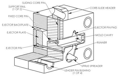

Two dies are used in die casting; one is called the "cover die half" and the other the "ejector die half". Where they meet is called the parting line. The cover die contains the sprue (for hot-chamber machines) or shot hole (for cold-chamber machines), which allows the molten metal to flow into the dies; this feature matches up with the injector nozzle on the hot-chamber machines or the shot chamber in the cold-chamber machines. The ejector die contains the ejector pins and usually the runner, which is the path from the sprue or shot hole to the mould cavity. The cover die is secured to the stationary, or front, platen of the casting machine, while the ejector die is attached to the movable platen. The mould cavity is cut into two cavity inserts, which are separate pieces that can be replaced relatively easily and bolt into the die halves.[17]
The dies are designed so that the finished casting will slide off the cover half of the die and stay in the ejector half as the dies are opened. This assures that the casting will be ejected every cycle because the ejector half contains the ejector pins to push the casting out of that die half. The ejector pins are driven by an ejector pin plate, which accurately drives all of the pins at the same time and with the same force, so that the casting is not damaged. The ejector pin plate also retracts the pins after ejecting the casting to prepare for the next shot. There must be enough ejector pins to keep the overall force on each pin low, because the casting is still hot and can be damaged by excessive force. The pins still leave a mark, so they must be located in places where these marks will not hamper the casting's purpose.[17]
Other die components include cores and slides. Cores are components that usually produce holes or opening, but they can be used to create other details as well. There are three types of cores: fixed, movable, and loose. Fixed cores are ones that are oriented parallel to the pull direction of the dies (i.e. the direction the dies open), therefore they are fixed, or permanently attached to the die. Movable cores are ones that are oriented in any other way than parallel to the pull direction. These cores must be removed from the die cavity after the shot solidifies, but before the dies open, using a separate mechanism. Slides are similar to movable cores, except they are used to form undercut surfaces. The use of movable cores and slides greatly increases the cost of the dies.[17] Loose cores, also called pick-outs, are used to cast intricate features, such as threaded holes. These loose cores are inserted into the die by hand before each cycle and then ejected with the part at the end of the cycle. The core then must be removed by hand. Loose cores are the most expensive type of core, because of the extra labor and increased cycle time.[11] Other features in the dies include water-cooling passages and vents along the parting lines. These vents are usually wide and thin (approximately 0.13 mm or 0.005 in) so that when the molten metal starts filling them the metal quickly solidifies and minimizes scrap. No risers are used because the high pressure ensures a continuous feed of metal from the gate.[18]
The most important material properties for the dies are thermal shock resistance and softening at elevated temperature; other important properties include hardenability, machinability, heat checking resistance, weldability, availability (especially for larger dies), and cost. The longevity of a die is directly dependent on the temperature of the molten metal and the cycle time.[17] The dies used in die casting are usually made out of hardened tool steels, because cast iron cannot withstand the high pressures involved, therefore the dies are very expensive, resulting in high start-up costs.[18] Metals that are cast at higher temperatures require dies made from higher alloy steels.[19]
| Die component | Cast metal | |||||
|---|---|---|---|---|---|---|
| Tin, lead & zinc | Aluminium & magnesium | Copper & brass | ||||
| Material | Hardness | Material | Hardness | Material | Hardness | |
| Cavity inserts | P20[note 1] | 290–330 HB | H13 | 42–48 HRC | DIN 1.2367 | 38–44 HRC |
| H11 | 46–50 HRC | H11 | 42–48 HRC | H20, H21, H22 | 44–48 HRC | |
| H13 | 46–50 HRC | |||||
| Cores | H13 | 46–52 HRC | H13 | 44–48 HRC | DIN 1.2367 | 40–46 HRC |
| DIN 1.2367 | 42–48 HRC | |||||
| Core pins | H13 | 48–52 HRC | DIN 1.2367 prehard | 37–40 HRC | DIN 1.2367 prehard | 37–40 HRC |
| Sprue parts | H13 | 48–52 HRC | H13 DIN 1.2367 |
46–48 HRC 44–46 HRC |
DIN 1.2367 | 42–46 HRC |
| Nozzle | 420 | 40–44 HRC | H13 | 42–48 HRC | DIN 1.2367 H13 |
40–44 HRC 42–48 HRC |
| Ejector pins | H13[note 2] | 46–50 HRC | H13[note 2] | 46–50 HRC | H13[note 2] | 46–50 HRC |
| Plunger shot sleeve | H13[note 2] | 46–50 HRC | H13[note 2] DIN 1.2367[note 2] |
42–48 HRC 42–48 HRC |
DIN 1.2367[note 2] H13[note 2] |
42–46 HRC 42–46 HRC |
| Holder block | 4140 prehard | ~300 HB | 4140 prehard | ~300 HB | 4140 prehard | ~300 HB |
The main failure mode for die casting dies is wear or erosion. Other failure modes are heat checking and thermal fatigue. Heat checking is when surface cracks occur on the die due to a large temperature change on every cycle. Thermal fatigue is when surface cracks occur on the die due to a large number of cycles.[20]
| Zinc | Aluminium | Magnesium | Brass (leaded yellow) | |
|---|---|---|---|---|
| Maximum die life [number of cycles] | 1,000,000 | 100,000 | 100,000 | 10,000 |
| Die temperature [°C (°F)] | 218 (425) | 288 (550) | 260 (500) | 500 (950) |
| Casting temperature [°C (°F)] | 400 (760) | 660 (1220) | 760 (1400) | 1090 (2000) |
Process edit
The following are the four steps in traditional die casting, also known as high-pressure die casting,[5] these are also the basis for any of the die casting variations: die preparation, filling, ejection, and shakeout. The dies are prepared by spraying the mould cavity with lubricant. The lubricant both helps control the temperature of the die and it also assists in the removal of the casting. The dies are then closed and molten metal is injected into the dies under high pressure; between 10 and 175 megapascals (1,500 and 25,400 psi). Once the mould cavity is filled, the pressure is maintained until the casting solidifies. The dies are then opened and the shot (shots are different from castings because there can be multiple cavities in a die, yielding multiple castings per shot) is ejected by the ejector pins. Finally, the shakeout involves separating the scrap, which includes the gate, runners, sprues and flash, from the shot. This is often done using a special trim die in a power press or hydraulic press. Other methods of shaking out include sawing and grinding. A less labor-intensive method is to tumble shots if gates are thin and easily broken; separation of gates from finished parts must follow. This scrap is recycled by remelting it.[14] The yield is approximately 67%.[22]
The high-pressure injection leads to a quick fill of the die, which is required so the entire cavity fills before any part of the casting solidifies. In this way, discontinuities are avoided, even if the shape requires difficult-to-fill thin sections. This creates the problem of air entrapment, because when the mould is filled quickly there is little time for the air to escape. This problem is minimized by including vents along the parting lines, however, even in a highly refined process there will still be some porosity in the center of the casting.[23]
Most die casters perform other secondary operations to produce features not readily castable, such as tapping a hole, polishing, plating, buffing, or painting.
Inspection edit
After the shakeout of the casting it is inspected for defects. The most common defects are misruns and cold shuts. These defects can be caused by cold dies, low metal temperature, dirty metal, lack of venting, or too much lubricant. Other possible defects are gas porosity, shrinkage porosity, hot tears, and flow marks. Flow marks are marks left on the surface of the casting due to poor gating, sharp corners, or excessive lubricant.[24]
Lubricants edit
Water-based lubricants are the most used type of lubricant, because of health, environmental, and safety reasons. Unlike solvent-based lubricants, if water is properly treated to remove all minerals from it, it will not leave any by-product in the dies. If the water is not properly treated, then the minerals can cause surface defects and discontinuities.
Today "water-in-oil" and "oil-in-water" emulsions are used, because, when the lubricant is applied, the water cools the die surface by evaporating, hence depositing the oil that helps release the shot. A common mixture for this type of emulsion is thirty parts water to one part oil, however in extreme cases a ratio of one-hundred to one is used.[25] Oils that are used include heavy residual oil (HRO), animal fat, vegetable fat, synthetic oil, and all sorts of mixtures of these. HROs are gelatinous at room temperature, but at the high temperatures found in die casting, they form a thin film. Other substances are added to control the viscosity and thermal properties of these emulsions, e.g. graphite, aluminium, mica. Other chemical additives are used to inhibit rusting and oxidation. In addition emulsifiers are added to improve the emulsion manufacturing process, e.g. soap, alcohol esters, ethylene oxides.[26]
Historically, solvent-based lubricants, such as diesel fuel and kerosene, were commonly used. These were good at releasing the part from the die, but a small explosion occurred during each shot, which led to a build-up of carbon on the mould cavity walls. However, they were easier to apply evenly than water-based lubricants.[27]
Advantages edit
Advantages of die casting:[11]
- Excellent dimensional accuracy (dependent on casting material, but typically 0.1 mm for the first 2.5 cm (0.004 inch for the first inch) and 0.02 mm for each additional centimeter (0.002 inch for each additional inch).
- Smooth cast surfaces (Ra 1–2.5 micrometres or 0.04–0.10 thou rms).
- Thinner walls can be cast as compared to sand and permanent mould casting (approximately 0.75 mm or 0.030 in).
- Inserts can be cast-in (such as threaded inserts, heating elements, and high strength bearing surfaces).
- Reduces or eliminates secondary machining operations.
- Rapid production rates.
- Casting tensile strength as high as 415 megapascals (60 ksi).
- Die casting fluid length is unaffected by solidification range, unlike permanent molds, sand castings, and other types.[28]
- Corrosion rates for die castings are slower than those for sand castings due to the smoother surface of the die castings.[29]
Disadvantages edit
The main disadvantage to die casting is the very high capital cost. Both the casting equipment required and the dies and related components are very costly, as compared to most other casting processes. Therefore, to make die casting an economic process, a large production volume is needed. Other disadvantages are:
- The process is limited to high-fluidity metals. Increased scrap rates can be caused by fluidity failure, and scrap costs in die casting are high.[30]
- Die casting involves a large number of parts, so questions of repeatability are particularly important.[31]
- Casting weights have previously been limited to between 30 grams (1 oz) and 10 kg (20 lb),[note 3][11] but from 2018 shots of 80 kilograms (180 lb) have become possible.[32]
- In the standard die casting process the final casting will have a small amount of porosity. This prevents any heat treating or welding, because the heat causes the gas in the pores to expand, which causes micro-cracks inside the part and exfoliation of the surface. However, some companies have found ways of reducing the porosity of the part, allowing limited welding and heat treating.[4] Thus a related disadvantage of die casting is that it is only for parts in which softness is acceptable. Parts needing hardening (through hardening or case hardening) and tempering are not cast in dies.
- During the cooling process, some of the material stuffs the tiny crevices of the mold under pressure, which creates excess burrs that require extra work to trim.[33]
Variants edit
Acurad edit
Acurad was a die casting process developed by General Motors in the late 1950s and 1960s. The name is an acronym for accurate, reliable, and dense. It was developed to combine a stable fill and directional solidification with the fast cycle times of the traditional die casting process. The process pioneered four breakthrough technologies for die casting: thermal analysis, flow and fill modeling, heat treatable and high integrity die castings, and indirect squeeze casting (explained below).[5]
The thermal analysis was the first done for any casting process. This was done by creating an electrical analog of the thermal system. A cross-section of the dies were drawn on Teledeltos paper and then thermal loads and cooling patterns were drawn onto the paper. Water lines were represented by magnets of various sizes. The thermal conductivity was represented by the reciprocal of the resistivity of the paper.[5]
The Acurad system employed a bottom fill system that required a stable flow-front. Logical thought processes and trial and error were used because computerized analysis did not exist yet; however this modeling was the precursor to computerized flow and fill modeling.[5]
The Acurad system was the first die casting process that could successfully cast low-iron aluminium alloys, such as A356 and A357. In a traditional die casting process these alloys would solder to the die. Similarly, Acurad castings could be heat treated and meet the U.S. military specification MIL-A-21180-D.[5]
Finally, the Acurad system employed a patented double shot piston design. The idea was to use a second piston (located within the primary piston) to apply pressure after the shot had partially solidified around the perimeter of the casting cavity and shot sleeve. While the system was not very effective, it did lead the manufacturer of the Acurad machines, Ube Industries, to discover that it was just as effective to apply sufficient pressure at the right time later in the cycle with the primary piston; this is indirect squeeze casting.[5]
Pore-free edit
When no porosity is allowed in a cast part then the pore-free casting process is used. It is identical to the standard process except oxygen is injected into the die before each shot to purge any air from the mould cavity. This causes small dispersed oxides to form when the molten metal fills the die, which virtually eliminates gas porosity. An added advantage to this is greater strength. Unlike standard die castings, these castings can be heat treated and welded. This process can be performed on aluminium, zinc, and lead alloys.[16]
Vacuum-assisted high-pressure die casting edit
In vacuum assisted high pressure die casting, a.k.a. vacuum high pressure die casting (VHPDC),[34] a vacuum pump removes air and gases from die cavity and metal delivery system before and during injection. Vacuum die casting reduces porosity, allows heat treating and welding, improves surface finish, and can increase strength.
Heated-manifold direct-injection edit
Heated-manifold direct-injection die casting, also known as direct-injection die casting or runnerless die casting, is a zinc die casting process where molten zinc is forced through a heated manifold and then through heated mini-nozzles, which lead into the moulding cavity. This process has the advantages of lower cost per part, through the reduction of scrap (by the elimination of sprues, gates, and runners) and energy conservation, and better surface quality through slower cooling cycles.[16]
Semi-solid edit
Semi-solid die casting uses metal that is heated between its liquidus and solidus (or liquidus and eutectic temperature), so that it is in a "mushy" state. This allows for more complex parts and thinner walls.[citation needed]
Low-pressure die casting edit
Low-pressure die casting (LPDC) is a process developed to improve the consistency and integrity of parts, at the cost of a much slower cycle time.[35] In LPDC, material is held in a reservoir below the die, from which it flows into the cavity when air pressure in the reservoir is increased.[35] Typical pressures range from 0.3 bar (4.4 psi) to 0.5 bar (7.3 psi).[35][36] Somewhat higher pressures (up to 1 bar (15 psi)) may be applied after the material is in the die, to work it into fine details of the cavity and eliminate porosity.[35]
Typical cycle times for a low-pressure die casting process are longer than for other die-casting processes; an engine block can take up to fifteen minutes.[35] It is primarily used for aluminum, but has been used for carbon steel as well.[35]
Integrated die-casting edit
Integrated die-casting refers to the high-level integration of multiple separate and dispersed aluminum alloy parts through a large-tonnage die-casting machine, and then formed into 1-2 large aluminum castings. Elon Musk's team first proposed this processing method during the Tesla manufacturing process which is Giga Press program.
See also edit
Notes edit
References edit
- ^ "Die Casting vs Other Processes". Archived from the original on 2016-09-23. Retrieved 2016-09-16.
- ^ Machinery's reference series, The Industrial Press, 1913, retrieved 2013-11-18.
- ^ About die casting, The North American Die Casting Association, archived from the original on 21 October 2010, retrieved 15 October 2010.
- ^ a b Liu, Wen-Hai (2009-10-08), The Progress and Trends of Die Casting Process and Application, archived from the original on 2012-03-14, retrieved 2010-10-19.
- ^ a b c d e f g John L., Jorstad (September 2006), "Aluminum Future Technology in Die Casting" (PDF), Die Casting Engineering: 18–25, archived from the original (PDF) on 2011-06-14.
- ^ Degarmo, p. 328.
- ^ Die Casting, efunda Inc, retrieved 2008-04-12.
- ^ a b FAQ About Die Casting, archived from the original on 21 October 2010, retrieved 12 April 2008.
- ^ Alloy Properties, The North American Die Casting Association, archived from the original on 2013-06-06, retrieved 2008-04-12.
- ^ Keller, Jeff (2021-01-12). "Larger Automotive Castings Drive Innovation in Molten Metal Delivery". Melt Pour. Foundry Magazine. Retrieved 2021-01-18.
new project at a large, California-based OEM of electric vehicles. … 105 kgs of molten aluminum … delivered in each shot.
- ^ a b c d Degarmo, p. 331.
- ^ "Draft". Archived from the original on 2021-10-23. Retrieved 2016-09-16.
- ^ "Parting Line". Archived from the original on 2021-10-26. Retrieved 2016-09-16.
- ^ a b c Degarmo, pp. 329-330.
- ^ Parashar, Nagendra (2002), Elements of Manufacturing Processes, City: Prentice-Hall of India Pvt.Ltd, p. 234, ISBN 978-81-203-1958-5
- ^ a b c Degarmo, p. 330.
- ^ a b c d Davis 1995, p. 251.
- ^ a b Degarmo, p. 329-331.
- ^ Davis 1995, p. 252.
- ^ Degarmo, p. 329.
- ^ Schrader, George F.; Elshennawy, Ahmad K.; Doyle, Lawrence E. (2000), Manufacturing processes and materials (4th ed.), SME, p. 186, ISBN 978-0-87263-517-3.
- ^ Brevick, Jerald; Mount-Campbell, Clark; Mobley, Carroll (2004-03-15), Energy Consumption of Die Casting Operations (PDF), Ohio State University, doi:10.2172/822409, (US Department of Energy Grant/Contract No. DE-FC07-00ID13843, OSURF Project No. 739022), retrieved 2010-10-15.
- ^ Degarmo, p. 330-331.
- ^ Avedesian, M. M.; Baker, Hugh; ASM International (1999), Magnesium and magnesium alloys (2nd ed.), ASM International, p. 76, ISBN 978-0-87170-657-7
- ^ Andresen (2005), pp. 356–358.
- ^ Andresen (2005), p. 355.
- ^ Andresen (2005), p. 356.
- ^ Han, Q.; H., Xu. "Fluidity of alloys under high pressure die casting conditions". Scripta Materialia. 2005. 53(1): 7–10.
- ^ "Die Casting". forcebeyond.com. 5 January 2018. Archived from the original on 2019-02-27. Retrieved 2021-06-03.
- ^ Dewhirst, B. "Castability Measures for Diecasting Alloys: Fluidity, Hot Tearing, and Die Soldering". Proceedings of the 4th International High Tech die Casting Conference – via HTDC. 2008.
- ^ "Castability Control in Metal Casting via Fluidity Measures: Application of Error Analysis to Variations in Fluidity Testing" (PDF). web.wpi.edu. Archived (PDF) from the original on 2021-06-03. Retrieved 2021-06-03.
- ^ "Idra introduces the world's largest die cast machine". Asosiasi Italia Pemasok Foundries. 2018-02-01. Archived from the original on 2021-04-19. Retrieved 2020-04-20.
capable to produce castings well beyond 80 kgs in weight over an unbeaten maximum allowed projected area. … manufacture of high-integrity Aluminium and Magnesium Die Cast components for the automotive sector, with focus on structural and safety critical components. … Injection velocity exceeding requirements of 10 m/sec
- ^ Bob, McClintic. "Trim Tooling, Necessary Evil, Value Added Process or Profit Opportunity" (PDF). Bob McClintic and Associates.
- ^ Butler, William A. (2008). "Vacuum High-Pressure die Casting". Casting. pp. 732–733. doi:10.31399/asm.hb.v15.a0005276. ISBN 978-1-62708-187-0.
- ^ a b c d e f Campbell, John (August 6, 2015). Complete Casting Handbook: Metal Casting Processes, Metallurgy, Techniques and Design. Butterworth-Heinemann. ISBN 9780081001202 – via Google Books.
- ^ "Low-pressure vs. high-pressure die casting". Kurtz Ersa Magazine. Retrieved 2023-12-10.
Bibliography edit
- Davis, J. (1995), Tool Materials, Materials Park: ASM International, ISBN 978-0-87170-545-7.
- Degarmo, E. Paul; Black, J T.; Kohser, Ronald A. (2003), Materials and Processes in Manufacturing (9th ed.), Wiley, ISBN 0-471-65653-4.
- Andresen, Bill (2005), Die Casting Engineering, New York: Marcel Dekker, ISBN 978-0-8247-5935-3.
External links edit
Further reading edit
- Why Zinc Alloy Die Casting Becomes the Prime Choice for Manufacturers?
- Where to find Zinc Die Casting Manufacturer?
- "ZINC DIE CASTING PROPERTIES GUIDE" (PDF). eazall.com. Retrieved 2022-03-06.