PT6 mods for Daher TBM [1]
Lift jets edit


A lift jet is a lightweight jet engine installed only for upward thrust.[2] Jet lift is the use of jet engine thrust to support V/STOL aircraft[3] and is obtained from lift jets on their own, lift jets in conjunction with lift/cruise engines with vectored thrust, or lift/cruise engines alone.
Jet lift using lift jets alone edit
Lift jets alone have only been used on experimental aircraft, such as the SC.1, and rigs, such as the SG 1262 for the VAK 191B.
Jet lift using lift jets in conjunction with lift/cruise engines edit
...such as operational Yak-38, and the experimental Dassault Balzac, Dassault Mirage IIIV, VJ101, Dornier D0.31, Yak-141.
Jet lift using lift/cruise engines edit
...such as the operational Harrier and experimental Yak-36 and Bell X-14.
British lift jets originated with Griffith's idea of using batteries of simple turbojets of high thrust to weight ratio and fixed in a near vertical attitude for VTOL.[4] Lift jets were not available for conducting the first trials to determine how to maintain an acceptable level of control and stability[5] for aircraft hovering with jet lift as opposed to the rotating wings of a helicopter rotor. Existing Nene turbojets were used mounted horizontally with deflected exhaust for hovering on the British TMR. Soviet equivalent tests were done using an existing RD-45F mounted vertically and then a non-afterburning version of an RD-9BP mounted vertically in their VTOL rig, the Toorbolyot.[6]
Lift jet installation and aircraft operating procedures have to prevent ground erosion and hot gas ingestion during hovering. A lift jet has to be started in flight prior to the aircraft slowing from wing-borne speed. This is a high cross-wind situation for the intake and compressor which have to operate acceptably in distorted airflow. A meteor had an RB108 installed vertically behind the cockpit to check in-flight starting.
The first engine of any type designed specifically for VTOL was the RB.108.[7] Design work started in 1954 with a requirement for a high thrust-to-weight and the provision of compressor air for aircraft reaction control jets.


Lift jets were installed in the SC.1, 4 vertically and one for propulsion. Eight RB.108 engines were installed in the Balzac and eight RB.162 engines in the Mirage IIIV. Five RB.108 engines were installed in a rig, the SG 1262, to support the VAK191B program, a VTOL replacement for the Fiat G.91. The 3 center engines simulated vertical thrust fron single lift/cruiseengine and front and rear engines simulated aircraft lift engunes.[8] RB.162-81 engines in the VJ 101C. Eight RB.162 engines in Dornier Do.31.
An alternative to the lift jet for vertical thrust is the lift fan used on the STOVL Lockheed F-35B version of the U.S. Joint Strike Fighter.
Ted Talbot Concorde details to Tornado edit
The Concorde program was instructed by its controlling British government ministry to give its intake design and control philosophy, which was government property, to the Tornado program. Germany had responsibility for the intake control system as part of the international work-sharing split and subsequently patented the control and sued the British Aircraft Corporation for patent infringement on the Concorde. At a meeting between the German inventor, his lawyer, and Ted Talbot, Chief of Propulsion Engineering, it became clear that there was no patent infringement as the inventor didn't understand the Concorde control system which was superior to that outlined in the his patent. In particular, at extreme low ambient temeratures the intake control system took over control of the engine because the engine wanted more air than the intake could supply. The inventor asked for further information to help his engineers overcome the problems with the Tornado intake, but Talbot refused.[9]
The British Ministry of Supply assigned Chief Engineer Ted Talbot from the Concorde development team to provide intake design assistance to the Tornado development team in order to overcome these issues, which they hesitantly agreed to after noting that the Concorde intake data had apparently already been leaked to the Soviet Union. The German engineers working on the Tornado intake were unable to produce a functional Concorde style intake despite having data from the Concorde team. To make the problem worse, their management team incorrectly filed a patent on the Concorde design, and then tried to sue the British engineers who had provided the design to them. The German lawyers realised that the British had provided the designs to the German team, and requested further information to help their engineers overcome the problems with the Tornado intake, but Chief Engineer Talbot refused. According to Talbot, the Concorde engineers had determined the issue with the Tornado intake was that the engine did not respond to unexpected changes in the intake position, and therefore the engine was running at the wrong setting for a given position of the intake ramps. This was because the Concorde had similar issues due to control pressure not being high enough to maintain proper angles of the intake ramps. Aerodynamic forces could force the intakes into the improper position, and so they should have the ability to control the engines if this occurs. The Tornado intake system did not allow for this. Due to the behaviour of the German management team, the British engineers declined to share this information, and so the Tornado was not equipped with the more advanced intake design of the Concorde.[10]
Downwash edit


.jpg)

.jpg)

Injury and adverse environment for ground personnel [12]


downwash diameter up increases efficiency and close to ground reduces hazards to people beneath and pilot vision over loose surfaces.

Compressibility was an extreme flight condition beyond the capability of the tail surfaces to maintain a state of equilibrium, ie adequate contribution to maintain balance and control from lift gradient dClh/dalphah x Sh, diving beyond Mn at which changes in wing flow Obert Change of trim and stability is due to change of angle of attack of tailplane with Mn so floating horizontal tailplane could eliminate. Then stab and trim independant of change in downwash angle 767 p.302
In aeronautics, downwash is the change in direction of air deflected by the aerodynamic action of the fixed wing of an aircraft, or the rotating wings of a helicopter rotor as part of the process of producing lift.
Downwash persists far behind an aircraft as a hazard to other aircraft. Downwash under helicopters hovering near ground with loose surface covering is a hazard to people underneath the helicopter and presents a control problem for pilots operating above sand and snow when brownouts and whiteouts restrict their view of the ground.
This article introduces the effects of downwash on the aircraft itself, namely its ability to balance itself, and the effects on other aircraft which fly through its downwash far behind. It is necessary to mention wake also as they work together in balancing the aircraft and presenting a hazard to other aircraft. Two hazardous downwash/wake events were discovered in the history of aircraft: the effect of increasing speed when World War 2 fighter aircraft first encountered supersonic flow over the wings, the introduction of the T-tail as part of the design package for rear-mounted engines on jet airliners.
All wings leave behind them a downwash and a wake in which the tail surfaces are immersed to varying degrees depending on their position relative to the wing and the angle of attack of the aircraft. The downwash determines the angle of attack for the tailplane and is measured in terms of the angle through which the air has been deflected down and is directly proportional to the lift coefficient[14] The downwash angle is called . The wake also influences the tail surfaces because it is a region of reduced energy air. It has a dynamic pressure lower than the free stream as it has its origins in the boundary layer flow from upstream surfaces.

For an aircraft with a tailplane the horizontal tail automatically returns the aircraft to a state of balance if it is disturbed by a vertical gust, for example. The tailplane interacts with the downwash angle to do this and it also needs enough dynamic pressure from the part of the wake it is immersed in, since its angle of attack and dynamic pressure are what enable the tail plane to produce the required vertical force to restore the aircraft to a balanced condition. The relevant downwash-related parameter is how much the tailplane angle of attack changes with each degree of aircraft angle of attack change brought about by the unexpected vertical gust. depsilon/dalpha.

Angle through which fluid stream is deflected down by aerofoil or other lifting body, measured in plane parallel to plane of symmetry close behind trailing edge; directly proportional to lift coefficient.[15] ie as measured at tailplane where it matters.
A downward vertical component of airflow induced by wingtip vortices [16] Downwash angle of flow behind wing reduced by compressibility burble. Change in downwash angle eliminated by dive recovery flap which maintained lift in face of burble.p.406
The variation in downwash is of interest behind, above and below the trailing edge of the wing. A lifting airfoil is trailed in flight by a wash which has a definite inclination corresponding to the factors producing the lift.[17]
Tailplane design includes positioning relative to the wing which depends on knowledge of direction and downward velocity of flow behind the wing, known as downwash, and also knowledge of the loss in dynamic pressure compared to the freestream which occurs in the wing wake. The wake is an extension of the low energy boundary layers from the top and bottom surfaces of the wing and its vertical extent ranges from small at low angles of attack where there is no separation of the flow on the wing to large for a stalled wing.

Some authorities consider it not as an angular measure but as a rate of change of momentum, equal but opposite to lift.Gun ie for lifting column efficiency
Not least, often taken to mean linear velocity of flow through helicopter main rotor in hovering flight. Gun
or wherever velocity is important ie personnel, objects, ground erosion
Angle through which fluid stream is deflected by rotor of rotary-wing aircraft, measured parallel to rotor disc. Gun
Downwash velocity: velocity of air mass with downward momentum imparted by helicopter rotor, lift fan, jet engine
An aircraft wing and helicopter rotor blade deflect air downwards and the downward motion is called downwash. Wing downwash varies with the lifting ability (lift coefficient) of the wing so, for example, changes with flap deployment for a particular wing design and planform type for different designs. It has a downward angle e and vertical velocity component w which vary with distance behind and above and below the wing trailing edge.[18] The horizontal tailplane is continually flying in downwash so the vertical force it produces depends on the how the downwash varies during a flight as aircraft speed and wing lifting behaviour vary from take-off to landing. The flow characteristics behind a wing include the downwash with its angle varying with lift coefficient, or angle of attack, and the dynamic pressure which varies in the wing wake with angle of attack and flow separation.
Downwash is induced by the wing vorticity [19] The direction and vertical component of the velocity of the downwash, vertical displacement of trailing vortex sheet, behind the wing contribute to the vertical tailplane force which affects the pitching stability of the aircraft. If the tailplane is immersed in the wing wake the tailplane force is also determined by the amount dynamic pressure is reduced below the free stream value. The wake is a rearwards extension of the boundary layer. Downwash behind stalled airfoils is important because of stability and loss of control at the stall. Origin of wake Fig.34[20]
Prediction of longit stability and control depend on knowledge of induced flowfield behind lifting surface. Shed vorticity tends to concentrate into two vortices resulting in roll-up of vortex sheet. [21]
Change in spanwise load distribution when Mcrit is exceeded. Decrease in lift coeff on section where Mcr exceeded. Change in spanwize lift distribution occurs. affect airplane trim and stability characteristics. Changes in spanwise distribution of load vary with magnitude of the spanwise variations of the section critical Mach number. Dive-recovery flaps increase lift where greater loss in lift occurs. [22]
NACA TN 42
A wing in flight is trailed by a wash with an inclination (downwash angle e) corresponding to the factors which produced the lift. At a given point e is proportional to the lift and angle of attack so as alpha varies so will e and if e changes more rapidly than alpha then tail force is destabilizing and vice versa. The main interest in downwash lies primarily in the angle of attack which it establishes at the horizontal tail which in turn determines the tail stabilizing force in pitching motion.
AGARD LS 63
Helicopter rotor disc or thrust generator produces downwash velocity by imparting momentum. Highest power economy , maximum thrust per HP, needs lowest possible induced velocity.
The low downwash produced by the slowly turning large rotors has important
implications in operating over environments where injestion due to recirculation can occur
from such soil characteristics as sand and gravel, and where high downwash energies are detrimental
to personnel or materiel in the operational area. The use of helicopters in great quantities,
particularly in military missions, demonstrates that its mission effectiveness is worth
the increase in cost
It can be shown that this condition of uniformity of the fully-developed downwash velocity is synonymous with minimization of the power required to generate a given thrust under assumed conditions of flight velocity, air density, and the cross-section area of the fully-developed slipstream. Thus, the power expressed by Eqs (2b) or (2c) may be called the ideal power (Pa) required, while its part related to the thrustgenerating process and represented by the second term in Eqs (2b) or (2c) may be named the ideal induced power
Rotary-wing aerodynamics book Downwash velocity . Helicopter rotor is lowest velocity thrust generator in hovering flight which gives highest thrust for energy consumption rate, Fig 1.2.
DOWNWASH IMPINGEMENT DESIGN CRITERIA FOR VTOL AIRCRAFT Dynasclences Report No. DCR-139
The problems associated with operations of VTOL air¬ craft In close proximity to the ground result primarily from the high-velocity slipstream generated by the aircraft lift devices. Compared to a helicopter, which also gives rise to operational problems over soft ground surfaces, the VTOL aircraft, because of the higher slipstream velocities involved, will generate more severe conditions. An indica¬ tion of the relation between disc loading and slipstream velocities, as generated by various types of lift devices, is presented in Figure 1. It may be noted that hurricane velocity, which is indicated as 65 knots, corresponds to an average velocity generated by an open propeller having a disc loading of 16 pounds per sqioare foot. The disc loadings proposed for future VTOL aircraft are many times this magni¬ tude, and therefore the severity of the problem can be easily appreciated.
Helicopter rotor downwash effects US Forest service Helicopters achieve their lifting capabilities by thrusting a large volume of air downward while in flight. They also create a "rotor wake" which can be useful to •agricultural appl icators when close to the ground, since the vortices provide excellent coverage of foliage. For the firefighter, however, this is a different story. He needs to understand and avoid possible downwash effects of low-flying aircraft of any type. Undersome fl ight conditions hel icopters can create the greatest effects.
Guidelines and rulesof thumb regarding best speeds to avoid such effects have been used but were never based on other than experience and opinions. Even then, fires were still affected by downwash or, more accurately , "rotor wake." Most felt that as long as a hover condition or flight below translation was avoided, the hazard was averted. This short study is aimed at providing more reliable guidelines regarding rotor wake and downwash and how to avoid their effects.
Flight Measured Downwash of the QSRA
The downwash slope, Ae/Aa aw , at the low-tail position is about 1.5 to 2 times the value of that at the high T-tail position. This means that the low-tail position provides less stability than the high T-tail position. This would increase the need for a stability augmentation system (SAS) for a low-tail configuration.
The trim changes would also be higher at the low-tail position increasing the need for a variable incidence horizontal stabilizer at the low-tail position. Automatic trim may be required as USB flap setting and thrust are increased on a low-tail configuration.
NACA TN 124 Munk
NACA L5C09 Notes on compressibility effects at subcrit speeds
A rational solution for the problem of longitudinal stability at high speeds requires a j.nom'ledge of the effects of compressibility on the downv/ash in the region of the horizontal tail surface. Studies of this problem for speeds belov; the critical have been reported by Husk in ref'erence 1 and by Goldstein and Yor'ng in reference 2. In reference 1 the dov^nwash at the tail is assumed to be unaffected b^?- Increases in Hach number for constant values of the lift coefficient
Jet engine performance as part of a powerplant or propulsion system edit
Performance is the overall energy conversion efficiency of the whole powerplant. A brief explanation considers some differences between a subsonic powerplant, such as an underwing or rear-fuselage position, and a supersonic one. In both cases the performance of a bare engine is changed as a result of adding features necessary for flight.
Powerplant for a subsonic aircraft edit
A subsonic engine installation has the following equipment which alters the bare engine performance: the inlet is an additional compressor with a pressure ratio of 1.8:1 at Mach 0.8 but entropy is generated from frictional effects of the air flowing along the duct surface: the nozzle also has flow losses: hydraulic pumps, electrical generators and compressor bleed to the aircraft reduce the thrust transferred to the aircraft. Just as the internal thrust is the resulting forward force from a combination of forward (thrust) and rearward (drag) forces inside the engine the thrust from the installation is usually reduced by those external drags which are affected by the position of the thrust levers and which are considered negative thrust.[23]
-
 PW305 bare engine with inlet (white) and nozzle/thrust reverser (green)
 -
 PW815 bare engine
 -
 PW800 engine nacelle
.jpg)
.jpg)
.jpg)
Powerplant for a supersonic aircraft edit
A Mach 3 powerplant is described as its inlet with internal supersonic flow needs more features compared to those required at lower speeds. In the inlet losses come from wall friction, shock waves and separated flow.[24] At the nozzle most loss comes from the exit static pressure not being equal to ambient, ie over or under expansion.[25] At supersonic speeds alot of energy is available in the air approaching an aircraft and the streamtube entering the engine inlet has its high speed converted to pressure which is added to that from the engine compressor. The inlet acts as a compressor and for a Mach 3 aircraft has a supersonic part followed by a subsonic part.
-
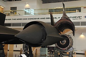 A view of the entry to an SR71 inlet looking in direction of airflow to the engine.
 -
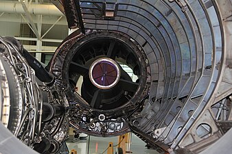 A view of the exit end of an SR71 inlet from the engine point of view.
 -
 A view of the rear of the powerplant showing features of the airframe nozzle
 -
 A rear view of the engine installed in the powerplant
.jpg)
_(2).jpg)
_(2).jpg)
.jpg)
The turbojet, a short-lived jet engine with too-high fuel consumption edit
The turbojet had a major shortcoming in its initial application to aircraft travelling at 500 mph. It used too much fuel because the speed of its exhaust wake exceeded the aircraft speed by too much. It would be replaced in 20 years for 500 mph aircraft with the bypass engine with lower wake velocity.
To produce thrust the propelling jet behind a propeller or leaving a jet engine has to be faster than the aircraft but not excessively so. An excessive wake speed wastes fuel. The propeller wake from an aircraft moving at 450 mph has a speed 10 MPH and for a turbojet 600 MPH.[26]
The functions of converting fuel into mechanical work followed by mechanical work into thrust were clearly separated for the first forty years of powered flight. Aircraft used an engine and propeller combination. The engine and propeller were developed separately. The engine and propeller efficiencies were independent. This independence was lost with the introduction of the turbojet. The working substance of the thermodynamic cycle of the turbojet is the mass accelerated to produce the thrust. The production of thrust by the continuous production of backward momentum is necessarily accompanied by a simultaneous production of kinetic energy which trails away and which is left behind without contributing to the thrust power. . And since momentum is proportional to speed and ke to speed squared, economy requires that speed of jet should be kept as low as possible and momentum kept up to required value by increasing mass flow rather than speed.[27]The propulsive efficiency is no longer independent of the thermodynamic cycle but becomes a function of the energy supplied and the thermodynamic efficiency of the cycle. Independence was regained by introducing supplementary air, ie bypass. Propulsive efficiency is independent of mass flow so increased thrust from mass flow rather than velocity.[28]
Thermal eff constantly improves as pr and TET increase. and gg turbine exhaust total pressure and temperature increase. More energy available to a power turbine driving a propeller or fan. For turbojet more energy available at nozzle which develops velocity and thrust. Improvement in thermal efficiency accompanied by increased power availability for turbofan and thrust for turbojet. for each lb air passing through gg. Therefore airflow requirement of gg to develop fixed level of thrust deceases as cycle pr and tet increase.[29]
The power lost, known as wake power to distinguish from thrust power, exists in the kinetic energy of the very high speed exhaust after it has left the engine. As such it is sometimes known as residual KE and residual velocity loss. A propeller also produces lost power because it also leaves behind residual velocity in its wake, but negligible in comparison.
Thrust without a nozzle edit

A convergent nozzle on a ramjet or gas turbine jet engine has a rearwards force acting on it. The purpose of the nozzle is to act as a restriction to the flow through the compressor and so set the operating pressure, or in the case of a ramjet to set the diffuser exit pressure. In doing so a nozzle has a drag force on it. Afterburning is an alternative way of setting turbomachinery operating pressure or, for a ramjet, higher fuel flow in the combuster. This is the basis for afterburning where, as more fuel is burned less nozzle (that is less area reduction) is required and thrust increases by the amount of nozzle drag reduction.[32] Afterburning nozzles when at maximum have a barely perceptible nozzlemore like a straight pipe exit. Combustion temperature rise is such that choking occurs at the exit of a straight pipe.[33] Straight pipes were also used on some early ramjets where thrust rather than range was most important.[34]
The majority of turboprop engines of the 1960's had thrust obtained primarily as a result of gas outlet velociy from the turbine without subsequent expansion in a nozzle. since gas is expanded to almost atmospheric pressure in the turbines.[35]
Increased compressor efficiency edit

Raising the efficency means reducing pressure loss or entropy generation. One source of loss originates with the angle the air meets the blade leading edge. Minimum pressure loss from this particular source occurs when the air approaches a blade head-on. Blades only operate over a narrow range of incidences before losses become unacceptable and the condition for blade stall is often taken as twice the minimum loss.[36] Other sources of loss and entropy production are boundary layers, mixing processes, shock waves, shock wave/boundary layer interaction, heat transfer and tip leakage.[37]
End bend HP compressor blades: HP blades being shorter than those upstream have a larger proportion of their length running in boundary layers (bl), the one at the casing ref tip and the one at the hub ref root. Since the bl air is slowed down the blade profile needs to be matched to the local velocity to reduce incidence and separation losses. Incorporation in the Rolls-Royce RB211-535E4 HP compressor was reported to increase efficiency by 1% giving a roughly 0.5% improvement in SFC.[38] Similar twisting at the tip to accommodate local airflow conditions only became possible with an understanding of the 3-D nature of the flow using CFD and is called Leading Edge Recambering.[39]
Turbine efficiency edit
All viscosity effects give continuous and cumulative increases in entropy, the result of losses or irreversibilities. boundary layers, complex flows in corners where blades meet end walls, at clearances where rotors and stators meet end walls, wakes where flow leaves blade trailing edges. Shock waves are sources of losses
JT3D and JT9D turbines compared [40]
-
 turbine velocity triangles
 -


Using bypass for better fuel consumption edit
The TF39 had a very low fuel consumption compared to the low bypass engines it superceded TF33/C141 due to higher thermodynamic cycle efficiency from high pressure ratio and high propulsive efficiency from high temperature high velocity core energy into low velocity high airflow in 8:1 bypass system.[41]
-
 Pratt & Whitney JT3 (1/4th scale) was the engine used for the company's first turbofan the JT3D.
 -
 JT3D
JT3D -
 The front fan was added to the JT3 engine to make Pratt & Whitney's first turbofan.
 -
 Afterburning J79. The J79 gas generator was used for the company's first turbofan.
 -
 The CJ805-21 made by adding an aft fan to the J79 gas generator.
 -
 bpr evolution
 -
 TF33 military transport turbofan with bypass ratio 1.42:1, TO turbine temperature 1610 F on a standard day 50 F, pressure ratio 16:1 introduced on C141 in 1965
 -
![TF39 military transport engine with bypass ratio 8:1, TO turbine temperature 2350 F on a hot day 90 F, pressure ratio 25:1, [42] introduced on the C5 in 1970](//upload.wikimedia.org/wikipedia/commons/thumb/e/ee/A_crew_chief_inspects_an_engine_of_a_436th_Military_Airlift_Wing_C-5A_Galaxy_aircraft_at_Freetown_International_Airport_prior_to_the_plane%27s_flight_to_Liberia_DF-ST-91-05139.jpg/330px-thumbnail.jpg) TF39 military transport engine with bypass ratio 8:1, TO turbine temperature 2350 F on a hot day 90 F, pressure ratio 25:1, [42] introduced on the C5 in 1970
TF39 military transport engine with bypass ratio 8:1, TO turbine temperature 2350 F on a hot day 90 F, pressure ratio 25:1, [42] introduced on the C5 in 1970

.png)
.jpg)
_J79-J-1K,_71KN,_7460rpm_at_Flugausstellung_Hermeskeil,_pic5.jpg)


![TF39 military transport engine with bypass ratio 8:1, TO turbine temperature 2350 F on a hot day 90 F, pressure ratio 25:1, [42] introduced on the C5 in 1970](/wiki/File:A_crew_chief_inspects_an_engine_of_a_436th_Military_Airlift_Wing_C-5A_Galaxy_aircraft_at_Freetown_International_Airport_prior_to_the_plane%27s_flight_to_Liberia_DF-ST-91-05139.jpg)
-

-
 JT8D showing size of commercial transport engine prior to replacement by big fa JT9D
 -
 JT9D
JT9D -
 Front view of an A319-112 CFM56-5B6 with its fan removed. The relative sizes of the air passages to the core and bypass duct for a bpr of 6:1 are apparent.
 -
 Rear view showing the relative sizes of the core exhaust and bypass duct air.

_Pratt_%26_Whitney_JT8D-9_turbofan_engine_nacelle(left_wing,_cowl_open)_left_front_view_at_Iruma_Air_Base_November_3,_2014_01.jpg)
.jpg)


Turbine cooling edit
Turbine materials and cooling[43]
-
-

-
 A turbine blade with thermal barrier coating. This blade has no tip shroud so tip leakage is controlled by the clearance between the tip and a stationary shroud ring attached to the turbine case.
 -
 Laser-drilled holes permit film cooling in this first-stage V2500 nozzle guide vane


.jpg)
Mixing edit
A free mixer, simple splitter between fan and primary streams,(also called annular used 535E4 [44] and forced mixer[45] also called chute mixer
Mixing transfers energy from hot/fast core to warm/slow bypass without using a heatexchanger or mechanical means. Mixer performance assessed by mixing efficiency and pressure loss.[46] Mixing reduces jet noise and needs to give low pressure losses and high mixing efficiency. Mixing increases entropy which shows as pressure loss.[47]
-
 Early forced mixer on civil Spey engine
 -
 Trent 700 showing common nozzle assembly with annular mixer, a simple splitter between fan and primary streams.
 -
 RB211-535E4 showing annular mixer.
 -
 JT8D showing forced or chute mixer

.jpg)
.jpg)

Tip clearance during compressor case shrinking edit

In early engines rubbing caused permanent damage which increased the clearances and fuel consumption. Honeycomb sealing was used on the J58 compressor case to minimse rub damage during rapid reductions in inlet ram-air temperature caused by the aircraft slowing very quickly. The lighter compressor case contracted faster than the heavier rotor.[48] One potentially catastrophic cause of rubbing has been contraction of the compressor case when flying in thick cloud containing supercooled water droplets. Known as centre-line closure in the Sapphire engine effects ranged from rotor seizure to loss of aircraft and crew following catastrophic damage to engine and surrounding systems. An abrasive material was added to the compressor casing to wear away the blade tips giving bigger tip clearances and a loss in performance.[49]
Performance retention edit
The static structures of an engine are a major contributor to the retention of performance as they maintain alignment between turbomachinery rotors and stators by virtue of their stiffness which is resistance to deformation or distortion when under load. The introduction of the big fans was a major jump in engine diameter and thrust and to prevent them being overly large and heavy they needed to incorporate new structural concepts. Mounted by conventional means the engines sensitive to backbone bending and casing distortion or out of roundness when operating at high thrust and with high inlet air loads during particular manoeuvres. The JT9D had what was called "an economical use of supporting structure and cases"[50] compared to the previous Pratt & Whitney turbofan, the JT3D. It had a compact lightweight design. Early flight testing on the Boeing 747 showed the large diameter and high thrust imposed a substantial couple at the engine mounts which caused backbone bending and case out-of-roundness. Distortion was reduced by moving the thrust transfer to a plane closer to the engine centreline where the thrust acts (instead of from the top of the exhaust case). CF6 thrust taken from a single location on the front mount, together with engine casing backbone bending deflections caused local case distortion and rubs, reduced with a thrust taken as 2 loads of half the intensity
RB211 short engine with stiff shafts and casings, gas path separated from structural casing mounted with radial flexibility so inertia and thrust forces in flight have min effect on tip clearances,
Performance retention has included passive and active clearance control on HP compressors, HP and LP turbines. Flowpath geometry to encourage abrasive particles and FO to enter the bypass duct rather than the HP compressor.
Case distortion causing clearance closure, rubs and performance loss had to be addressed on the JT9D and CF6. It was caused by high thrust and flight-induced inlet airloads at high aoa. Thermal matching of static and rotating parts preceded active control To address transient closure due to thermal effects.
During taxi, take-off and landing: Fan to booster axial spacing allows large and medium particle cf.GP7200,PW4000. P2.5 bleed air extracts most remaining GP7200. Elliptical spinner deflect particles into bypass duct GP7200. RB211 good spacing of core splitter relative to fan
JT8D retention characteristics , rigid case construction and gas path with relativey loose clearances comp to latest so not affected by bending from inlet air loads during rotation. Primary loss from hot section thermal distress and comp blade roughness and erosion. [51]
A 1985 NASA defined energy efficient engine for General Electric . Others include reduction in installed sfc, noise, emissions, economic benefits in terms of reduced DOC.[52] High level of performance should be retained over the long term as engine is in service. ACC comp and turbines, red sp thrust ref fpr and bpr [53] retention p.17
RB211 performance retention features [54] Retention of sfc relies on keeping low clearances in compressors and turbines under all running conditions. 3 shaft layout allows each rotor held in 2 bearings on stiff structure with double casings to isolate structural loads from gas path. Easier to maintain concentricity between static and rotating parts to maintain close clearances. Trent core mounted p.26. Wide chord fan and spacing of splitter relative to fan centrifuges majority of debris. 3 shaft short stiff shafts and casings Also AGARD CP 237 end RTD-3/4
Everyday indications of the existence of stress in a solid object edit
Stresses due to "tension" and "compression" An elastic band increases in length when pulled which indicates a tensile stress in the material (stress and change in dimension coexist or go together and for a particular material are related by a constant number known as its modulus). The width or cross section gets smaller because the band volume doesn't change. Alternatively, if the band were arranged lengthwise in a suitable apparatus which squeezed and reduced its cross section the smaller dimension would indicate a compressive stress in the material.
Stresses due to "bending" which include tension, compression and "shear" If a tree trunk falls across a stream and is used as a footbridge there is no stress apparent in the tree when walked on because it bends by an imperceptible amount under the weight of a pedestrian. A windy day produces a force on a slender tree trunk sufficient to visibly bend it so there must be stresses in the trunk, and these may be high enough to break the trunk in extremely high winds. The bending produces tension stresses in the windward, or convex, side and compression stresses in the opposite side.
If a thin plank is placed across a stream it will sag noticeably if someone stands on it. If a deep section wood beam is placed alongside it will not sag by a noticeable amount. However, the noticeable rigidity is not due just to the thickness of wood which may be shown if thin planks are stacked on top of one another to give the same thickness as the beam. In this case there is notieable sagging because the plank surfaces slide against one another. The sliding is a shearing action and may be prevented by glueing the planks together, in which case there is now a shear stress in the glue thickness. This illustrates the existence of shear stresses which are present through the whole depth of a bent beam.
Stresses due to "twisting" In this case an engineering value which indicates the state of stress is presented to every new-car buyer as a selling feature in the car brochure.
Overview edit
Wide chord fan refers to the fan blades on a modern turbofan jet engine having a ducted fan with a specific blade geometry - In layman's terms, they would be described as having wider blades than other jet engines. a blade with a longer chord relative to its length (lower aspect ratio) than previous narrow-chord fan blades with snubbers (part-span shrouds)[55]. Snubbers were needed to avoid blade failures caused by flutter. A wider chord increased the blade stiffness so snubbers were no longer needed. The technology for wide-chord fan blades in high bypass engines was pioneered by Geoff Wilde at Rolls-Royce in the 1970s and first entered airline service in the Rolls-Royce RB211-535E4 engine.[56]
History of wide-chord fan and compressor blading edit
The structural benefits of low aspect ratio (with 50% wider chord) compressor blading (a fundamentally stiffer blade and less prone to failure) were proposed after Conway high pressure compressor blade failures at Rolls-Royce. Wide-chord blades were rig tested in the Tyne compressor rig and an aerodynamic benefit (increased surge margin) was reported by Geoff Wilde in 1954.[57] In 1957, after a technology exchange with Rolls-Royce, General Electric redesigned the J93 compressor with long-chord blades and used it as the basis for the General Electric TF 39 and CF 6 compressors.[58]
Independently in the Soviet Union the Tumansky R-11 turbojet, first run in 1953, entered service in 1958 with very wide chord compressor blades (with low aspect ratio of about 1.5) and high pressure ratio for that time.[59]
A Spey replacement, the RB203 Trent, first ran in 1967. Its fan used 21 wide-chord snubberless blades.[60] Increasing the size of such a medium bypass engine from 39 in. diameter and producing 10,000 lb thrust to a high bypass 86 in. and 40,000 lb thrust (RB211-22) meant fan blades had to be narrower to keep their weight within the strength capability of the fan disc and containment around the fan case. The also needed mid-span snubbers to prevent them bending (flexural modes) and twisting (torsion modes) (fluttering) and breaking.[61] A wide-chord carbon fibre composite blade was light enough and stiff enough to not require snubbers and appeared at first to be suitable. When it was found to have some fundamental deficiencies in meeting all the requirements for an aero-engine fan blade a solid Titanium blade was substituted, but to keep within the weight limit for a fan blade it had to be narrow together with snubbers to prevent it fluttering. So all high bypass engines had long, narrow blades with snubbers. Narrow chord blades had several drawbacks compared to wide chord blades.
A wide chord fan (hollow Titanium blades) would not go into service until 1984 in the RB211-535E4.[62]
Examples of the changeover to wide-chord (snubber-less) blades are: Rolls-Royce - civil RB211-535C to RB211-535E4 (hollow titanium with honeycomb core) military Turbo Union RB199 to Eurojet EJ200[63] General Electric - CF-6 to GE90 (composite blades)[64] Pratt & Whitney - civil PW 4168 to PW 4084 (hollow titanium)[65], military F100 to F119[66] Pratt & Whitney Canada - JT15D to PW305[67] CFMI - CFM56-3 to CFM56-7B[68] Aviadvigatel - PS-90 to PD-14


_fan.jpg)
_starboard_engine_w_o_inlet_cowl_(2736595928)_(2).jpg)
.jpg)
.jpg)
.jpg)


A wide chord fan blade was part of the RR engine proposal (RB178-51) to Boeing for the 747. The blade was to be made from carbon composite material (trademarked Hyfil). Earlier RB178 configurations still used high aspect ratio fan blades with mid-span snubbers. The wide-chord carbon-fibre fan blade was carried over to the RB211 for the Tristar. It was finally abandoned by Rolls-Royce in 1970 after a catastrophic engine failure during fan flutter testing in a 40 knot crosswind. The RB211 went into service with Titanium fan blades with snubbers.
Wide chord blades have greater stability margins and move air more efficiently across blade surface due to longer chords. Increased stability removed need for mid-span shrouds needed on narrow chord blades which are a source of losses and flow blockage. [69]
Benefits[70] edit
Increased efficiency snubbers in supersonic flow cause significant blockage and eff loss, improved surge margin see pic, greater resistance to FOD-wide chord cf's out, better noise characteristics. Each blade moves more air with larger chord so fewer blades needed. Fewer blades ref stators less noise transmission thro rotor.
trend to high solidity low aspect ratio for stalling pressure rise coefficient v. diffusion length to exit passage width[71]
Key design considerations edit
Fan/compressor blades have to withstand strikes from objects such as . They naturally bend and twist which causes stresses which will break them from fatigue. They have to be light enough to be retained by a disc when spinning at high speed. They have to raise the pressure of the air passing by them (stage pressure ratio) whilst at the same time not stalling (have to operate with adequate surge margin).
A wide chord fan has fewer, wider blades compared to the narrower blades on earlier technology fans. The blades are often hollow and made from titanium. The wide-chord fan blade was designed and developed at Rolls-Royce Barnoldswick in Lancashire. The manufacturing process uses superplastic forming, diffusion-bonded technology to achieve a light weight, strong design.[72]
References edit
- ^ George, Fred. "Pilot Report: Daher Socata TBM 900." Archived 2017-08-25 at the Wayback Machine Aviation Week, 22 May 2014.
- ^ https://archive.org/details/cambridgeaerospa0000guns/page/346/mode/2up
- ^ https://archive.org/details/cambridgeaerospa0000guns/page/328/mode/2up?q=jet+lift
- ^ https://archive.org/details/developmentofjet0000guns/page/162/mode/2up, p.163
- ^ Rolls-Royce From the Wings Military Aviation 1925-1971,Harker 1976,ISBN 0 902280 38 4, p.119
- ^ https://archive.org/details/yak-36-yak-38-yak-41-red-star-36_202310/page/5/mode/2up, p.6
- ^ https://archive.org/details/introductiontovs0000kohl/page/212/mode/2up?q=rb+108
- ^ https://web.archive.org/web/20030315044307/http://www.vstol.org/GermanVSTOLFighters.pdf V/STOL Fighter Programs in Germany: 1956–1975, viewgraph 39
- ^ Talbot, Ted (2013). "17". Concorde: A Designer's Life: The Journey to Mach 2. History Press. ISBN 978-0752489285.
- ^ Talbot, Ted (2013). "17". Concorde: A Designer's Life: The Journey to Mach 2. History Press. ISBN 978-0752489285.
- ^ Systematic study of the factors contributing to post-stall longitudinal stability of T-tail. Figure 4
- ^ https://archive.org/details/DTIC_AD0608185/page/n17/mode/2up
- ^ https://archive.org/details/DTIC_AD0608185/page/n17/mode/2up
- ^ https://archive.org/details/cambridgeaerospa0000guns/page/188/mode/2up
- ^ Gunston
- ^ History of aerodynamics,Anderson p.285
- ^ Naca TN 42
- ^ TN 42
- ^ Dynamics of Atmospheric Flight,Etkin,{{|ISBN0 486 44522 4,Fig.6.9
- ^ NACA report 651
- ^ NACA RM A9D20
- ^ NACA CB L4L07
- ^ https://onlinelibrary.wiley.com/doi/book/10.1002/9781118534786, "Performance of the Jet Transport Airplane", p.213
- ^ The Aerothermodynamics of Aircraft Gas Turbine Engines, Oates,Editor,AFAPL-TR-78-=52,WP AFB, Ohio, pra 6.2
- ^ The Aerothermodynamics of Aircraft Gas Turbine Engines, Oates,Editor,AFAPL-TR-78-=52,WP AFB, Ohio, pra 6.6
- ^ Gas Turbines and Jet Propulsion, Sixth Edition,Geoffrey Smith 1955,Iliffe & Sons Ltd.,London S.E.1, p.53
- ^ Buckingham p.85
- ^ L530a p.16
- ^ Transport aft-fan p.3
- ^ https://link.springer.com/book/10.1007/978-981-16-8028-1, 'The Vortex and the Jet',Decher,p.147
- ^ https://ntrs.nasa.gov/citations/19970019923,"Predicted Performance Of A Thrust-Enhanced SR-71 Aircraft With An External Payload",Connors,NASA Technical Memorandum 104330,p.6
- ^ The Jet Engine,Rolls-Royce Limited, Publication Ref.T.S.D.1302,July 1969,#rd Edition,p.215
- ^ 'Jet Propulsion for Aerospace Applications,Hesse and Mumford,Library of Congress No. p.387
- ^ https://archive.org/details/DTIC_AD0041742, Ramjet Technology, Chapter 13, Exit Nozzle Design, Streiff,p.1
- ^ "Principles Of The Theory Of Aviation Gas Turbine Engines", Kulagin 1967,Technical Translation,US Army Foreign Science And Technology Center,FSTC-HT-23-539-71, p.267/268
- ^ https://arc.aiaa.org/doi/10.2514/1.9176, "Ideas and Methods of Turbomachinery Aerodynamics: A Historical View", p.18
- ^ https://asmedigitalcollection.asme.org/turbomachinery/article-abstract/115/4/621/434211/The-1993-IGTI-Scholar-Lecture-Loss-Mechanisms-in?redirectedFrom=fulltext,"Loss Mechanisms In Turbomachines",93-GT-435,Abstract
- ^ Flight International,30 July 1983,p.269
- ^ https://www.google.com/search?client=firefox-b-d&q=Modern+Advances+in+Fan+and+Compressor+Design+Using+CFD+balin, Modern Advances In Fan And Compressor Design Using CFD, Riccardo Balin,p.2
- ^ Oates 18.0.0
- ^ https://asmedigitalcollection.asme.org/GT/proceedings/GT1982/79573/V002T02A017/229788,"Performance Improvement Features of General Electric Turbofan Engines",p.1
- ^ Installed Performance of the TF39 Engine, SAE 690653,p.1
- ^ 'Improving Engine Efficiency Through Core Developments',Dr.James Heidmann,AIAA Aero Sciences Meeting,January 6,2011,'Turbine materials cooling'
- ^ Design Aspects Of Recent Developments in Rolls-Royce RB-211 524 Powerplants,Parkes,88-GT-301,p.6
- ^ Energy Efficient Engine Exhaust Mixer Model Technology Report, Kozlowski and Larkin,NASA CR 165459,p.8 and Fig.4
- ^ https://www.sciencedirect.com/science/article/abs/pii/S2451904918305602,
- ^ https://www.semanticscholar.org/paper/Performance-improvement-of-propulsion-systems-by-of-Mundt-Co./7829a6594f8477ce6e623767e3f5fd33b9b546cb,
- ^ https://archive.org/details/CIA-RDP63-00313A000500130069-8
- ^ https://archive.org/details/javelinfromcockp0000cayg/mode/2up?q=javelin+from+the+cockpit 'Javelin-From The cockpit',ISBN 978-1-84884656-2, p.110
- ^ https://nyaspubs.onlinelibrary.wiley.com/doi/abs/10.1111/j.1749-6632.1968.tb15216.x "Development of the High Bypass Turbofan",Gaffin and Lewis,p.588,Figure 14
- ^ CP2190 fourth paper
- ^ CR168219 p.2
- ^ 1978 CR159584 p.3/5/9
- ^ CP2190 p.83
- ^ The Cambridge Aerospace Dictionary,Bill Gunston 2004,ISBN 978 0 511 33833 5
- ^ https://www.thefreelibrary.com/How+Rolls-Royce+played+wilde+card-a0404035229
- ^ Axial Compressor Development At Rolls-Royce Derby,1946-1962,A.McKenzie2009,Rolls-Royce Heritage Trust,ISBN 978 1 872922 42 3,p.63
- ^ Axial Compressor Aerodesign Evolution at General Electric,Leroy H.Smith,Jr.,Journal of Turbomachinery July 2002 Vol.124,The American Society of Mechanical Engineers, p.327
- ^ Low Aspect Ratio Axial Flow Compressors:Why and What It Means,Arthur J.Wennerstrom,SAE paper 861837,Society of Automotive Engineers,p.6
- ^ Rolls-Royce Aero Engines,Bill Gunston 1989,ISBN 1 85260 037 3, p.208
- ^ "Wide chord fan proved in more than five years of service",The Journal of the Royal Air Force Air Engineer Branch 1990,p.12,13, article reprinted from the Rolls-Royce magazine
- ^ p.51,57,174
- ^ The Development Of Jet And Turbine Engines 4TH Edition,Bill Gunston2006,ISBN 0 7509 4477 3, p.179
- ^ The Development Of Jet And Turbine Engines 4TH Edition,Bill Gunston2006,ISBN 0 7509 4477 3, p.100
- ^ The Development Of Jet And Turbine Engines 4TH Edition,Bill Gunston2006,ISBN 0 7509 4477 3, p.71
- ^ Jane's All The World's Aircraft1992-933, edited by Mark Lambert,ISBN 0 7106 0987 6, p.696
- ^ Optimization Studies for the PW305 Turbofan,Karanjia and Harvey, AIAA 90-2520,AIAA/SAE/ASME/ASEE 26th Joint Propulsion Conference,Orlando,FL,p.5
- ^ ref smartcockpit.com - CFM Flight Ops Support,Tuesday 13 December 2005,Overview Technical Features,p.13
- ^ patent 5 141 400
- ^ "Developing the Rolls-Royce Tay' N.J.Wilson,paper 88-GT-302,The American Society Of Mechanical Engineers,p.3
- ^ GE book for engineers p.3-20
- ^ "GE Aviation: Engine Education, 2008". Archived from the original on 2008-07-08. Retrieved 2008-08-14.
- "Types of Turbines, University of Bath, UK". Archived from the original on 2009-03-17. Retrieved 2008-08-14.
The turbojet was originally developed to raise the speed of aircraft to about 500 mph. In 1934 von Ohain did studies which showed the advantages [1] Whittle also did a specification for a turbojet powered 500 mph aircraft.[2] The turbojet would replace the propeller to produce thrust. The propeller converted the power in the propeller shaft to thrust by increasing the momentum of the air flowing through it. The turbojet, as the working fluid flowed through the engine, experienced forward and rearward forces on the internal parts. The forward are greater than the rearward and the difference may be calculated from the internal flow conditions and this is the thrust of the engine. It is much more simply calculated from the difference between the conditions at entry and exit (thrust equation).
Since the thrust producing machine is a heat engine work is done by allowing the excess pressure in the exhaust to return to the lowest pressure available to it (that of the surrounding atmosphere). This is done using a reduced area exit for the exhaust duct called a nozzle. The enthalpy in the low velocity flow in the exhaust duct is converted to kinetic energy so exhaust flow leaves the nozzle with a velocity higher than the speed of the aircraft. Long before the turbojet was invented it was a familiar fact in naval and aeronautical engineering that propulsion by fluid reaction wasted less energy if thrust was obtained by a large, low speed continuously flowing stream[3] of water or air. The turbojet was developed as the easiest solution to enable aircraft speeds of about 500 mph whilst it was understood that a lot of fuel would be wasted by producing a small, high speed jet with a velocity much higher the the speed of the aircraft. As a result of this disadvantage patents were written at the same time the first turbojets were being made, eg "Improvements relating to the Propulsion of Aircraft",Frank Whittle,March 1936.[4] Whittle estimated a turbojet, with an exhaust velocity three times that of an aircraft at 500 mph would have a propulsive efficiency of 50%.
The purpose of the turbojet is to use a gas generator to provide a supply of gas at a pressure above that of the atmosphere for the purpose of doing useful work in its subsequent expansion in a propelling nozzle.
The converging propelling nozzle, a necessary evil
The converging propelling nozzle is necessary in so far as its exit area, smaller than the jetpipe area, shares the task of setting the compressor pressure rise and airflow with the turbine nozzle guide vane area. Thrust is generated inside the engine by forces on the internal duct surfaces and moving parts as the air flows from the intake to the exhaust. In the first part of the engine (compressor and combustor)), forces are in a forward direction. In the second part (turbines and propelling nozzle) forces are in the opposite direction (drag). The converging nozzle itself produces a drag force, not thrust. The smaller the exit area the greater the drag. At the same time the smaller nozzle increases pressures in the compressor and combustor which are the thrust sources inside the engine.
There is an alternative way to back pressure the compressor. If the volume of each pound of gas that passes along the jetpipe each second is increased
In certain circumstances, where thrust is all-important, the nozzle drag may be reduced or entirely eliminated (early subsonic ramjets used a straight-pipe exhaust if maximum thrust was required for intercept acceleration as opposed to lower fuel consumption for range). A much more common example is the use of afterburning. When the exhaust gas is heated in the afterburner the nozzle opens up (produces less drag ie more thrust). This is because the increase in volume of each pound of gas passing each second in the afterburner has the same effect on compressor operation as a smaller nozzle.
An aircraft flying at a particular speed needs the same thrust (as set by the aircraft drag) regardless of how the thrust is produced. If a propeller is used it increases the speed of the approaching air by a small amount to produce the thrust (a particular 16.4 feet diameter propeller at 437 mph passed 6000lb of air per second and produced 3280 lb thrust by increasing the air speed through the propeller by 14 mph[5]). If a turbojet is used the high pressure/high temperature gas used for the engines thermodynamic cycle makes the jet. In this case the speed of the jet is very high. The pressure and temperature remaining in the gas after the turbines have finished with it gives sonic speed as the gas leaves the propelling nozzle (a particular early turbojet passed 173 lb of air per second and produced 11,000 lb of thrust by increasing its speed by 1,180 mph[6].
Cycle
The ramjet has an operating cycle basically similar to that of other air-breating engines, namely compression, burning and expansion.
Design
A typical ramjet
Unlike most airbreathing engines it has no moving parts in the engine proper. This makes it relatively simple, easy to fabricate and inexpensive.
Early ramjets reqd max thrust with no regard for efficiency straight tailpie often used. Efficiency became paramount so nozzle geometry important.[7]
Acceleration to sonic or supersonic velocity is The function of the exhaust nozzle so formation of thermal throat at combustion chamber exit is avoided. So pressure drop in nozzle tends towards ambient. [8]
A ramjet is a tube in which air is compressed by high velocity ramming, mixed with fuel and accelerated by the rapid increae in its specific volume (volume of each pound of gas) accompanying the combustion process. If maximum thrust is required with no regard for fuel consumption, as was often the case with early US ramjets,[9] the combustion chamber is designed (has the appropriate inlet Mach number, combustion temperature ) to achieve sonic velocity at what is known as a thermal throat (heat addition in a straight duct causes subsonic flow to accelerate to Mach 1 Rayleigh flow) and the exhaust leaves the engine through a straight pipe.[10] Thus a constricting nozzle is not a necessary prerequisite to producing ramjet thrust and as such there are three types of nozzle: straight pipe, converging and converging-diverging.
Tailpipes with 100%exits will produce more thrust than those with smaller throats.[11] The efficiency with which thrust was produced became most important which meant the function of accelerating the flow was given to the nozzle and the combustion chamber was no longer required to have a thermal throat.[12] Equation expresses sum of internal forces as a function of of the airflow rate and entering and leaving jet velocities. Exit nozzle contributes drag force so thrust to weight increases if exir area increased.<ref.ARS 1957 April </ref.
A high static pressure can be supported in a shaped duct by adding heat to he compressed internal flow by burning fuel with the compressed air. Heating the air causes large increase in specific volume and because specific dimensions of ramjet duct are fixed high static pressure of diffused air causes accel through tailpipe . Corresponding reaction force supports high static pressure acting on forward portion of duct. Max static pressure depends on Mach number and effectiveness of diffuser design.[13]
Cite error: A <ref> tag is missing the closing </ref> (see the help page).
[14]
By raising the temperature of the air the greatly increased volume is restricted by the too-small tailpipe which enables the ram air compression effect to maintain a high diffuser pressure.[15] The two principal parts are the forward part, the diffuser, and the rear part, the combustor. A ramjet doesn't need a nozzle to produce thrust although a nozzle (convergent or, for supersonic speeds, convergent-divergent) is required to improve performance over a wide flight envelope. The diffuser provides forward acting pressure on its internal surfaces, ie the source of the thrust. If there is no nozzle the heat release in the combustor maintains the pressure at the exit from the diffuser at a sufficiently high level to produce Mach one at the combustor exit[16](gas in a straight pipe accelerates from subsonic speed to Mach one with heat addition Rayleigh flow), in which case the combustor exhaust leaves the engine through a straight pipe.
Combustor adds energy so that thrust may be produced. The pressure recovery is able to support a combustion chamber pressure whose ratio to atmospheric pressure is sufficient to cause choking. Air specific impulse depends only on properties of gases and flame temperature.[17]
2 basic types , max thrust to weight at expense of fuel consumption for short-range interceptor type. Long-range bombardment with fuel consumption important and best overall. The straight pipe exit does not expand the jet, expansion to ambient pressure takes place in the atmosphere. So uses more fuel than constricted nozzle which expands to ambient. Max fuel economy when exit nozzle geometry gives expansion to ambient.Cite error: A <ref> tag is missing the closing </ref> (see the help page).
thermal stresses creep [18]
what are thermal stresses p.121 [19]
heat transferred in 2 ways p.309 [20]
aerodynamic heating from compression of still air, also causes friction heating within boundary layer p.154[21] [22]
The need to understand and design thermal structures began with supersonic flight in 1947. Aerothermal loads on external surfaces require selection of materials and design of structures which can withstand aerothermal loaods of high speed flight. consist of pressure, skin friction and aerodynamic heating . AH is predominant structural load. Elevatedtemps degrade materials ability to withstand loads because elastic properties like E reduced, allowable stresses reduced, time-dependant material behaviour,creep, becomes significant. Thermal stresses introduced because constrianed thermal expansions and contractions. increase deformantion ,alter buckling loads . X 1B studied aerodynamic heating effects by measuringskin temps , difficulties became known as thermal barrier , X2 first research aircraft to explore thermal thicket at over M 2.5 up to 3.2. Next major thermal structural research was X15.
p.9,72,484 ,655,670, 871,901, 1037, 1069[24]
p.535 [25] p.60 X 15 aerodynamic heating loads [26]
Thermal stress loading cycle ie heating and cooling each flight , creep prolonged time at temperature, overageing reduces static strength prolonged time at temperature . Difference in internal and external structural temps during supersonic climb produces thermal stress , dies away as equalize during cruise , then repeated during descent with opposite sign . Thermal stresses arise from differential expansion or contraction of adjacent structure p.23[27]
One of the main concerns caused by aerodynamic heating arises in the design of the wing. For subsonic speeds, two main goals of wing design are minimizing weight and maximizing strength. Aerodynamic heating, which occurs at supersonic and hypersonic speeds, adds an additional consideration in wing structure analysis. An idealized wing structure is made up of [[spar
inlet cone edit
An inlet cone, as a part of an Oswatitsch-type inlet, is an air compressor which uses supersonic air to raise the static pressure of air entering the subsonic diffuser in front of a gas turbine engine or ramjet combustor. It may also be used to supply high pressure air to other systems on supersonic missiles. Its function is to minimize the loss in total pressure which occurs when supersonic air slows down to subsonic speed. If allowed to occur naturally (ie through a normal shock) , the downstream device would gradually lose its thrust-producing ability as flight speed increased. Except for scramjet engines, all airbreathing jet engines need subsonic airflow to operate properly, and require a diffuser to prevent supersonic airflow inside the engine. At supersonic flight speeds a conical shock wave, sloping rearwards, forms at the apex of the cone. Air passing through the conical shock wave (and subsequent reflections) slows to a low supersonic speed. The air then passes through a strong normal shock wave, within the diffuser passage, and exits at a subsonic velocity. The resulting intake system is more efficient (in terms of pressure recovery) than the much simpler pitot intake.
Purpose edit
Purpose edit
An inlet cone, as a part of an Oswatitsch-type inlet, is a supersonic air compressor (supersonic diffuser). It provides a low-loss shock system to compress the air before passing it to a subsonic diffuser which further raises the pressure. If allowed to slow down naturally in front of an engine (ie through a plane shock) the resulting losses would gradually reduce the engine thrust-producing potential to zero with increasing speed. At supersonic flight speeds a conical shock wave, sloping rearwards, forms at the apex of the cone. Air passing through the conical shock wave (and subsequent reflections) slows to a low supersonic speed. The air then passes through a strong normal shock wave, within the diffuser passage, and exits at a subsonic velocity. The resulting intake system is more efficient (in terms of pressure recovery) than the much simpler pitot intake.
The purpose of the inlet cone, as part of Oswatitsch inlet, is the same as design feature for a subsonic inlet, ie to deliver required air flow to compressor or ramjet combustor with highest possible static pressure and smoothest possible velocity distribution. [28] However, supersonic flight speeds supplying the required airflow doesn't occur naturally because changes to the engine airflow can only be communicated at the speed of sound. In addition the high static pressures required for high overall pr and high thermal efficiency doesn't occur naturally (ie through plane shock) because decel from supersonic to sub through a single plane shock causes unacceptable energy losses, so much so that at Mach 3.5 all engine thrust would be lost. Thrust doubly dependent on pressure recovery.[29] So a protruding cone is added to the inlet to cause two or three shocks which collectively have lower loss than single plane shock. In addition the correct positioning of the cone shock relative to the inlet lip area provides the same airflow as the engine requirement.
The airflow entering an engine inlet for aircraft speeds above about Mach 1.6[30] has to be regulated by a protruding cone (or angled plate for square inlets). This is because the airflow taken by the engine from the exit of the inlet is regulated by the pilots thrust lever/fuel burned in engine combustor/compressor speed and the two airflows do not vary in the same way at different aircraft speeds and thrust settings. No regulation is required at subsonic speeds because the engine airflow requirement is able to move forward ( at the speed of sound) beyond the inlet. If the inlet is fixed its area will only be correct for the engine flow at a particulat flight Mach number and amient air temperature, critical condition.[31] If the engine requires less flow the inlet will operate in a high drag condition (spillig air) subcritical, with normal shock in front of inlet lip. Also shock poition unstable gives buzz. If more air normal shock moves along duct towards engine becoming stronger so bigger pressure loss and engine inlet pressure less. less thrust, supercritical. These two penalties result from fixed inlet. Serious propulsion system losses at off design only minimized with variable geometry system. Variation of cowl lip area and compression surface geometry by translating fore or aft to provide optimum location of oblique shock system or angla of surface adjustable for same purpose.
The inlet and engine when considered separately have different airflow chatacteristics and will only work well (low loss and stable for inlet, good ram pressure, ie low ilnet pressure loss, for engine ie high overall pr))together at the operating condition for which the inlet has been designed, ie a specific inlet area. .[32]
A cone is part of the inlet which supplies air to jet engines in supersonic missiles and aircraft. The inlet has to pass air to the engine[Note 1] with an acceptably small loss in total pressure[Note 2] and without causing unacceptable drag by spilling air around the outside of the inlet (spillage drag).[Note 3] A fixed position cone defines the inlet area for a ramjet combustor, or engine, airflow. For supersonic flight it produces the shock system which is necessary to give an acceptable loss in total pressure at a particular aircraft speed (ie at the intake design speed, eg Mach 1.7 for the English Electric Lightning). A cone with an adjustable axial location is used if the extra weight and complexity is an acceptable penalty for an improvement in ram pressure covering a wider range of aircraft speeds. A cone may be used for external compression inlets, which are suitable up to about Mach 2.2, and mixed or internal/external inlets for design speeds higher than about Mach 2.2.eg Blackbird. Changing ke into pressure with least possible losses. and at same time keeping drag to minimum. Normal shock ahead of missile to be avoided in all cases. The amount of air which flows through is regulated so shock occurs in the subsonic diffuser rather than ahead of it. has only secondary effect on recovered pressure but can lower drag remarkably. Slow the air to slow supersonic speed with oblique shocks and normal shock to slow to high subsonic speed then compression in subsonic diffuser. Supersonic flow transformed into subsonic through oblique followed by normal. [33] Then p.41 for int/ext, first compressed on a compression shock cone then introduced into duct interior and after more compression or shocks air is slowed up until finally reaching subsonic , further pressure increase through subsonic diffuser until reaches engine compressor or ramjet combustor. Fig. 1 shows decrease in total-pressure loss and increase in static pressure with total number of shocks, oblique and final normal.[34]
Diffusers transform velocity head of incoming flow into static pressure. Diffusers of ramjet engines have same function as compressors of gas turbine engines. The greater the pressure increase in the diffuser the greater the thermal efficiency of the engine. Geometrical form of diffuser is determined by Mach number of approaching flow. Two ways to characterize the action of a diffuser are recovery and drag. At high supersonic flight velocities energy losses in diffuser with normal shock become large and recovery factor small. To decrease losses powerful normal shock replaced with weaker oblique shocks concluding with weak normal shock. To form oblique inlet has a spike protruding from inlet opening. After passing through first shock supersonic flow behind shock wave deviates from original direction and moves parallel to surface. Normal shock appears at duct entry or behind it. [35]
Shape edit


The inlet is an air compressor (increases static pressure) and at supersonic speeds air is compressed by causing it to turn away from its incident path. This is done by deflecting it with a cone (an inclined flat plate does the same in a square intake). A shock wave is formed at each path change and the cone may have more than one angle (known as bi-conic for two, eg 24 and 31 degrees for a Bristol Thor ramjet with a design speed of Mach 2.5).[37] More shockwaves are required to compress the air with an acceptable loss in total pressure at higher design speeds.
The shape of the rear of the cone (unseen inside the duct) is related to the internal surface of the duct for efficient subsonic diffusion as the air slows to the compressor entry Mach number. The rear cone is shaped for a similar reason to the protruding front. The front is shaped to minimize loss in total pressure as supersonic flow slows down and static pressure rises. The rear minimizises loss in total pressure as subsonic flow slows down and static pressure rises.
Operation edit
Shockwaves accompanied in decrease in available energy. Ramjet diffuser mode of operation determined by heat released in combusor. Supercr when heat released less than design. Pressure recovery is an efficiency factor. Shocks adjust to flight speed and pressure requirements of engine. [38] When heat released in cc is such that back pressure at exit from diffuser causes normal shock to be positioned at entry is critical condition (design). Total pressure ratio depends on pr for supersonic diffuser and pr for subsonic diffuser
As well as having high ram recovery diffuser air-handling characteristics whichare matched with engine as well as low drag and good flow stability. The airflow matching characteristics are shown with area considerations. Air flow requirements fixed by pumping characteristics of engine.too much or too little air is detrimental todiffuser performance. The inlet area has to be of the proper size. which depends on the area of the approaching "cylinder' of air which w
An inlet is an air compressor with a pressure rise that becomes significant to the performance of a powerplant (inlet, engine and supersonic (divergent) nozzle if separate from the engine).[Note 4] as aircraft speeds approach the speed of sound. The inlet supplies compressed air to the engine compressor which compresses it further before it enters the combustor. For operation at supersonic speeds a cone is added to the inlet to prevent unacceptable pressure loss as the air slows down to below the speed of sound. For efficient conversion of the kinetic energy of a supersonic airstream into ram pressure must slow down to low supersonic Mach number before the normal shock occurs. The slowing down may be accomplishhed with low total pressure loss by locating one or more oblique shocks ahead of the diffuser by using a projecting cone.[39] It does this by making the air slow down from supersonic speed in two stages (an oblique shock and a plane shock) by the time it enters the enclosed ducting leading to the engine compressor or the ramjet combustor.
Operation of the diffuser at subcrit condition has a characteristic similar to surging of compressor since the inlet is also a compressor with pr v mass flow which becomes unstable.[40] when airflow through diffuser is reduced below its maximum rate (known as the "critical" condition) to a "subcritical" condition, by throttling engine for example which increases back pressure, the normal shock is expelled and the shock system oscillates in and out, known as "buzz" condition. Max rate occurs when engine flow requirement occurs at inlet entry area. If area doesn't match engine requirement air spilled or terminal shock drawn towards engine. subcritical stability known as buzz, external compression supersonic
For speeds lower than design the inlet has to be able to operate at a rate of entering volume flow less than the maximum entering volume flow permitted by the inlet. A reduction of volume flow causes buzz. Volume flow regulation. [41] Constant volume engine operation [42]
Supersonic diffuser at design condition: operation of diffuser and engine entirely consistent. diffuser operates steady with few losses and least external resistance, productivity is max, coeff of flow is 1 , in operation operates over wide range of partial load conditions , various M,alt,rpm. Part load characterized by 1) change and estruction of shock system 2)ejection of plane shock 3)unstable op of diffuser 4)appearance of sub and supercrit regimes. When carrying capacity of throat unable to pass flow entering inlet terminal shockejected , increases total pressure losses and external resistance, decreases flow through diffuser as a result of jet spreading, usually leads to surging. Inlet jet can no longer completely enter inlet so external part flows round outside casing. So decrease in flow to engine and thrust. Joint operation of inlet and compressor flow must be equal and done automatically or forced with control elements p.107, if diffuser uncontrollable , if dif not in state to pass flow taken by engine shock moves into diff and air density decr and so vel incr and airflows automatically conform p.109, . SS diff can be controlle by adjustments of diff form. Movement of cone axially, change in throat area, bypass. Axial movement forwards with no change to shock angle moves shock forward of lip, spreading increases and carrying capacity decreases. Movement inside diff shock approaches lip and spreading decr which incr carrying capac. control of flow with axial movement only works if min area changes at same time achieved by corresponding shaping of internal surface of ducting. With incr in rpm (either incr in physical revs,lower flight M, incr alt, lowering of ext temp , then comp flow incr , corresp incr in diff flow by moving cone inside diff. etc for less revs. Complexity of moving cone avoided by bypass F106. On take off have to move cone right in side and open aux inlets.[43]
The engine performance characteristics, thrust,SFC, depend on conditions of operation incl atmosph, flight characteristis M and alt, control of eng through controllable variables , interaction with aircraft inlet exhaust. p.220. Engine may have only one contr variable fuel, or more A8, IGV, ab fuel. p.227 with fixed geom have just fuel and rpm and egt limiting. Flow similarity fixed in the engine components but intr of inlet
rpm lock up J58
Notes edit
- ^ The inlet doesn't slow the air down. The air would slow down even without an inlet because the engine has the characteristics of a choked hole with a variable area and the flow is set by the area. The area varies with the amount of fuel burned in the engine.
- ^ approaching air has kinetic energy rel to aircraft.
- ^ The engine airflow is constant at a particular throttle setting or fuel flow. .
- ^ A supersonic nozzle is separate from the engine on the Lockheed SR-71 Blackbird and General Dynamics F-111 Aardvark. The divergent part may be part of the engine, eg General Electric J79 and Pratt & Whitney TF30.
The main purpose of an inlet cone, as a part of Oswatitsch-type inlet, is to slow the flow of air from supersonic flight speed to a subsonic speed before it enters the engine. Except for scramjet engines, all airbreathing jet engines need subsonic airflow to operate properly, and require a diffuser to prevent supersonic airflow inside the engine. At supersonic flight speeds a conical shock wave, sloping rearwards, forms at the apex of the cone. Air passing through the conical shock wave (and subsequent reflections) slows to a low supersonic speed. The air then passes through a strong normal shock wave, within the diffuser passage, and exits at a subsonic velocity. The resulting intake system is more efficient (in terms of pressure recovery) than the much simpler pitot intake.
Introduction edit
The following refers to subsonic aircraft which are required to cruise as close to the speed of sound as possible (early jet bombers, jet airliners, business jets). To do this they use swept wings to reduce the drag penalties (and extra fuel consumed) associated with the shock waves which occur at such speeds. This is done, in the first instance, by choosing a sweep angle appropriate for the cruise Mach number and then, by suitable airfoil shaping, minimizing the strength (which causes wave drag) of any shock waves and any boundary layer separation (which contributes to pressure drag) which occurs if the shock is strong enough.
Sweep raises the speed at which drag starts to rise due to the formation of shock waves. The airfoil profile, which comprises curvature and thickness, is adjusted to minimize shock strength, as indicated by the loss in total pressure,[44] and boundary layer separation.
Shock waves can form on parts of an aircraft moving at less than the speed of sound. The curving airflow around the top surface of the wing, for example, is accompanied by airspeeds faster than the freestream (by an amount known as supervelocity[Note 1]), together with pressures lower than freestream pressing on the wing surface (static pressure[Note 2]).[45] If the aircraft is moving fast enough the addition of the supervelocity will result in the speed of sound being exceeded, in the first instance, in just a localized supersonic region. The velocity is higher, and the static pressure lower, than the freestream values because the air is following a curved path.[Note 3] . This localized supersonic flow must return to the subsonic freestream velocity and pressure by the time it leaves the surface of the wing. However, because air has a variable density (the source of compressibility effects), slowing down from above the speed of sound to below it happens in a thin sheet of air known as a shock wave where abrupt changes occur as a jump (discontinuity) to higher density, higher static pressure and lower velocity. The presence of a shock wave causes wave drag due to the shock wave itself (the stronger the shock, the higher the drag) and also pressure drag if the shock wave is strong enough to cause the boundary layer to separate.
With objects where there is a sudden reduction in profile/thickness and the local air expands rapidly to fill the space taken by the solid object or where a rapid angular change is imparted to the airflow causing a momentary increase of volume/decrease in density, an oblique shock wave is generated. This is why shock waves are often associated with the part of a fighter aircraft cockpit canopy with the highest local curvature, appearing immediately behind this point.
At the point where the density drops, the local speed of sound correspondingly drops and a shock wave can form. This is why in conventional wings, shock waves form first after the maximum Thickness/Chord and why all airliners designed for cruising in the transonic range (above M0.8) have supercritical wings that are flatter on top resulting in minimized angular change of flow to upper surface air. The angular change to the air that is normally part of lift generation is decreased and this lift reduction is compensated for by deeper curved lower surfaces accompanied by a reflex curve at the trailing edge. This results in a much weaker standing shock wave towards the rear of the upper wing surface and a corresponding increase in critical mach number.
Unswept wing edit
The lift on a wing is caused by air following the curved upper and lower surfaces of its airfoil sections. If an unswept wing moves sideways at the same time as moving forwards (sideslips) the sideways airflow does not contribute to lift because that part of the airflow is not following a curved path past the wing. Curvature is necessary to cause the change in velocity and static pressure needed to produce a force on the wing. A similar sideways component of the airflow results if the wing is turned sideways (yaws) while moving forwards. In both cases the pressure distribution on the wing is determined by that component of the motion in a direction normal to the leading edge.[46]
Wing sweep edit
A swept wing introduces the same effect with its sweep angle alone, ie with no sideslip or yaw. Its advantage lies in creating a wasted span-wise flow component so the Mach number of the perpendicular component is made less than the free stream.[47] It has a velocity component which is wasted, ie lost to lift production. The remaining component, which follows the lift-producing wing curvature, is slower than the approaching air which is at the flight speed of the aircraft. The advantage, and the most common reason for using a swept wing, is that the aircraft can go faster before the wing causes the airflow on the top surface to reach the speed of sound (at which condition the drag on the wing rises rapidly). The disadvantage is in the lost velocity component which means a swept wing has less lift (a lower lift coefficient and lower lift curve slope) than an unswept wing.[48] This means high speed aircraft with highly swept wings need more attention to high lift devices for satisfactory take-off and landing performance.[49]
Lack of effective sweep at fuselage and tip edit
A swept wing has two types of sweep angle. The geometric angle which the aircraft is built with and which exists at the leading edge/the 1/4 chord line. The aerodynamic angle which changes with flight condition and high lift configuration. It coincides with the geometric in the mid half-span but is less approaching the fuselage and wing tip unless remedial action is taken to increase it in both locations to match the mid span sweep at the design condition. The aerodynamic sweep is the isobar sweep angle and is important because the local maximum Mach number is that which is perpendicular to the isobar at that location.[50] Shock waves will form at too low a speed in these locations whilst the goal is for shocks to form all along the span at the same aircraft speed, ie at the design condition.
The middle part of the wing has isobars with the same sweep as the wing but towards the ends the presence of the fuselage and the end of the wing at the tip cause the isobars to bend rather than remaining parallel to the leading edge. In these two regions the isobar sweep angle, instead of being parallel to the leading edge, is reduced and does not follow the wing physical sweep angle and so the benefits of sweep are reduced which causes the appearance of shock waves at a lower flight speed. Relevant Mach number for local max Mn is that perpendicular to isobars,[51] Also see [52] The wing and body have to be reshaped in these areas to restore the full effect of wing sweep, ie maintain isobar sweep angle.[53]
The isobar sweep angle at a particular point is indicative of the Mach number at that point [54]
When wave drag is delayed by keeping local effective flow over top surface below the speed of sound by using sweep and thinness supersonic flow patterns appear at the junction between the wing and fuselage and at the tips. A subsonic flow pattern may be retained by waisting the fuselage so wave drag does not occur earlier there than on the main part of the wing.[55] Higher effective camber near root than can be explained by curvature of airfoil, causing lines of equal pressure and velocity to slide aft of appointed positions on middle of span. The wing has less aerodynamic sweep than structural. accelerates flow and increases effective camber near root. So reduce physical camber of root while increasing camber of outboard. Physical camber inboard must actually be negative to get effective camber down to desired level. Highly cambered outboard have blunt le and very high Cl to ensure stall only at v high alpha. Inboard rel sharp le and low Cl to ensure stall earlier than tip.[56]
Ideally straight isobars run right up to fuselage and attempts to do this get close enough to reap the benefits of swept wing. Isobars tend to curve rearwards at root and forwards at tip.[57] Negative camber and max thickness forward p.186 to counter adverse root effects.[58]
Original production model DC-8 had disappointing drag as did the 990. 720 as 707 except more forward max thickness and reduced nose camber increased cruise 0.78/0.79 to 0.82. Suggests 707 Upper surface isobar pattern far from ideal.[59]
An early jet airliner with le root sweep to maintain isobar sweep was Caravelle.[60] Shape the wings and fuselage together such that chordwise pressure distribution on wings at design condition should be independent of spanwise position and component of local mach number normal to fully swept isobars thus obtained should be less than one. Should be possible to ensure flow over wings is free from shock waves and wing wave drag is low.[61] Kuchemann tip used to sweep isobars rearwards and delay drag rise eg VC10. [62]
Straight wings used on low subsonic aircraft as flight envelope does not allow critical compressibility effects to occur up to design diving speed/Mn. ie max level 0.6 and dive about 0.7 para 7.4 Toren Pressure distribution on top of wing as shown by isobars: Gain obtained in Mcrit less than expected assuming isobars parallel to span from root to tip. Presence of root and tip bend isobars in direction normal to flow fig 6.3 Stinton (as with unswept wing) so effect of sweep reduced so suitable measures have to be taken to counteract presence of root and tip. Full effect of sweep has to be restored by eliminating these effects.p247 Toren Isobar sweep with and w/o body fig 6.19 Stinton
as soon as Supersonic flow on top of wing terminates in shock wave of appreciable strength which thickens bl sig drag rise occurs p242 Toron
objective of high speed wing design pattern of approx straight isobars on top surface (crit for drag divergence except rear loading sections) as this is swept back approx equal to sweep angle then drag diverg occurs at same Mn along span . Early example of aerodyn eff wing Victor p247
Sweep should not be more than min required , reduces lift curve slope causing wing to be twisted if bent upwards with lift so gust loads reduced p251 Toren
neg root camber fig 6.20 Stinton
The swept wing works because it creates a wasted component of the incoming streamwise flow and uses the remaining flow to create lift. As such the swept wing has less lift than a straight wing due to the lost velocity component. Spanwise has little effect on pressure distribution over the airfoil section.[63] The lift-producing part of the aircraft velocity is thus less than the aircraft velocity
Distribution of velocities and pressures along wing doesn't depend on longitudinal flow , due only to lateral flow . Nature of flow and pressure distribution change depends on config of airfoil in plane normal to le and alpha. So aero characteristics same as unswept airfoil with free stream vel Vn inf. Flow over swept wing due primarily to partial realization of sideslip effect. Middle of wing characterized by mutual influence reducing sweep (sideslip) angle. In tip region there is appreciable deflection of streamlines compared to sideslipping wing [64]
DC-8 cruise M 0.85 means 35 deg sweep for conventional wing design at that time but penalised low speed perf and structural strength so camber changes as follows, (highly cambered outboard with blunt le give high lift coeff so stall afetr inboard. Inboard rel sharp le and low lift coeff so stall first at lower angle)Direction and speed (velocity) of flow controlled by pressure distribution on wing. Lines of equal pressure (isobars) should be parallel to span for best results. Much higher effective camber near root than explained by airfoil profile causing lines of equal pressure and velocity to slide aft of appointed position on center of wing. Aerodynamically wing has less sweep than structurally. Effect reinforced by presence of fuselage which increases effective camber near root. Effect decreases with speed so wing retains all disadvantages of full structural sweepback at low speeds. So physical camber reduced inboard and increased outboard . Phys camber inboard must be negative to get required effective camber.[65]
Le glove helps maintain isobar sweep [66][67]
Proper wing design gets rid of buffeting and pitch-up associated with uncontrolled flow separation on various parts of wing.[68]
Although swept wings delay drag rise other problems mean aerodynamicists want to use as little sweep as possible.[69] DC-8 would have required 35 deg with small rad leading edge with low speed perf and structural strength penalized.
Benefits (Whitford Airliner) delay and reduction of subs drag rise, (Whit Combat) delay reduction subs drag rise,reduction transonic trim changes, extension of buffet boundaries , drag reduction in supersonic flight
Penalties (Whit Airliner) reduction lift curve slope, higher drag due to lift, reduction max lift, reduces effectiveness of high-lift devices (Whit Combat) reduction lift curve slope, increased drag due to lift, roll due to sideslip, tip sta
Notes edit
- ^ The supervelocity at a location is the amount by which the local velocity is different from the freestream, greater than being a positive supervelocity and less than negative. It is greater the more severe the curvature (ie the smaller the radius of curvature). If the curvature is convex it is positive. If concave it is negative.
- ^ The static pressure is given as a change in static pressure compared to the freestream value. It is then expressed as a proportion of the freestream total pressure, or dynamic pressure, 'q'. In this form it is called the pressure coefficient, Cp, and is used to present airfoil pressure distributions on both the upper and lower surfaces. The upper surface Cp is shown with increasing magnitude, but negative, in the upward direction and the lower surface with increasing magnitude, but positive, in the downward direction. Using this presentation the area between the upper and lower surface pressure lines is proportional to the lift on the section.
- ^ Where the surface curvature is most pronounced (radius of curvature smallest) the velocity will be a maximum and the pressure a minimum.
Use in aircraft edit

Water injection was used during WWII in reciprocating engines for combat aircraft to increase power in emergency situations during enemy engagements, and is still used for air races with competing entries flying WWII aircraft. It is an obsolete technology used to increase take-off thrust and power for aircraft jet and turboprop engines (superceded by increased temperature capability and higher bypass ratios).[70] It has been used to increase maximum speed of supersonic aircraft for a speed record attempt and for interception of very fast, high flying reconnaissance aircraft. It has been studied as a means to reduce NOx emissions during take-off to reduce pollution around airports. It is used with the engine being motored by the starter or alternatively at idle for compressor washing.
Piston engines. Usually, the fuel mixture is set at full rich on an aircraft engine when running it at high power settings (such as during takeoff). The extra fuel does not burn; its only purpose is to evaporate to absorb heat. This uses fuel faster and also decreases the efficiency of the combustion process. By using water injection, the cooling effect of the water lets the fuel mixture run leaner at its maximum power setting. Many military aircraft engines of the 1940s utilized a pressure carburetor, a type of fuel metering system similar to a throttle body injection system. In a water-injected engine, the pressure carburetor features a mechanical derichment valve that makes the system nearly automatic. When the pilot turns on the water injection pump, water pressure moves the derichment valve to restrict fuel flow to lean the mixture while at the same time mixing the water/methanol fluid into the system. When the system runs out of fluid the derichment valve shuts and cuts off the water injection system, while enriching the fuel mixture to provide a cooling quench to prevent sudden detonation.
Due to the cooling effect of the water, Otto cycle aircraft engines with water injection can be made to produce more power through higher charge densities at the time of combustion. The additional charge density is typically achieved by allowing higher manifold pressures before the onset of detonation. This is normally done by adding or increasing the amount of forced induction or further opening of the throttle. However a similar result may be achieved via higher engine stroke. This has historically been the primary use of a water injection systems in aircraft.
The extra weight and complexity added by a water injection system was considered worthwhile for military purposes, while it is usually not considered worthwhile for civilian use. The one exception is racing aircraft, which focus on making a tremendous amount of power for a short time. In this case, the disadvantages of a water injection system are less important.
Turbine engines. Water, and water/methanol, injection has been used to increase take-off thrust for early military aircraft or to maintain constant take-off thrust (known as flat rating) to higher ambient temperatures for civilian aircraft. It has also been used to the increase maximum speed of supersonic aircraft. It is proposed to reduce NOx emissions around airports (water injection has been used to reduce NOx emissions from industrial gas turbines since ). All these uses are short duration due to the limited capacity of water tanks and the high water flow rates required. Example engines include turbojets Pratt & Whitney J57, turboprops Rolls-Royce Dart and turbofans Rolls-Royce Spey and Pratt & Whitney JT9D. Water was injected at the compressor inlet, or just before the combustion chambers, or into the combustion primary zone together with the fuel. Since turbine temperature limits the available thrust during take off the cooling effect lets the engine run at higher RPM with more fuel injected and more thrust created without overheating.[71] A secondary thrust-increasing effect comes from the mass flow of the water which is added to the airflow which enters the engine. Early Boeing B-52 and Boeing KC-135 aircraft powered by Pratt & Whitney J57 engines used water injection to increase take-off thrust and the dense black smoke severely restricted visibility when aircraft took off at 15 second intervals if there was no crosswind to disperse the smoke.[72]. An emissions test on a KC-135 engine, the J57-59W, showed a major increase in smoke when using water injection attributed to quenching the combustion reaction.[73] From a smoke point of view the combustion can be seen consisting of two separate zones with considerable soot forming in the fuel rich primary zone and consumed in the high temperature region downstream.[74] These aircraft would be re-engined in later years with more advanced engines which gave the required thrust without needing water injection.
Early versions of the Boeing 707 fitted with Pratt & Whitney JT3C turbojets also used water injection to restore thrust on hot days, as did Boeing 747-100 and 200 aircraft fitted with Pratt & Whitney JT9D-3AW and -7AW turbofans;[75] this system was not included in later versions fitted with higher thrust engines which did not need thrust augmentation on take-off. The BAC One-Eleven airliner also used water injection for its Rolls-Royce Spey turbofan engines. Filling the water tanks with jet fuel instead of water led to the Paninternational Flight 112 crash.[76]
This method has been used for short duration (due to limited coolant capacity) increases to an aircraft's normal maximum speed. "Operation Skyburner", which gained a world speed record with a McDonnell Douglas F-4 Phantom II,[77] and the Mikoyan Ye-266 (Mig 25).[78] Both used a water/alcohol spray to cool the air ahead of the compressor.
Water and detergent solutions are sprayed into the compressor during different types of washing procedures which include turning the compressor at starter motor speeds, for aircraft engines, and running the engine under load at its rated speed for industrial engines.[79]
Water is sprayed and frozen water in the form of ice balls (artificial hailstones) is fired into the engine during certification testing to prove the engine operation flying in severe inclement weather.
T56-A10W P-3A water alcohol J75-P-19W F-105D water + afterburner [80]
Evolution of the J57 during the design process edit
The design for the J-57 was based on running demonstrator engines with progressively higher pressure ratios during which time the split compressor was introduced with valves between the compressors to give an additional exit to allow the first compressor to work properly at low speeds. Variable angle stators in the first stages would have also allowed higher pressure ratios without the mechanical complication of two independently spinning compressor/turbine assemblies which need one shaft spinning inside the other. More bearings are required to support the two spools compared to a single spool with variable stators. P&W chose two spools as they knew more about bearings than variable stators.
P&W was aiming for 12.6:1 which was the optimum pressure ratio with the reduced air leakage they expected to achieve. This compared to the optimum pressure ratio of 6:1 for the then current state of the art leakage. A controlled amount of leakage is required into the
A shortfall in performance was rectified by basing the compressors on the PT2 compressor with which they had the most experience and knowledge. The cylindrical compressor casing used up to this point, with constant od, was changed to a constant id LP compressor which gave the tapering casing to achieve a smaller exit area for the smaller volume occupied by the compressed air at the design condition. The HP still used a constant od and the inner gas path was tapered for the smaller volume air leaving the HP . The smaller outside diameter of the HP gave the engine a wasp-waist look. It resulted in a 500 lb weight reduction as the outside of the engine was brought closer to the engine centerline. It also allowed accessories to be installed closer to the centerline which reduced the diameter of the nacelle (less drag).
Calculations showed the shaft design had a resonance in the running range so was shortened leaving less length for the combustion. The cans used an unusual arrangement
The development phase edit
Engine development for a new engine design starts with the assembly of the first engine, followed by its run and strip to check for wear or damage from the run. A development program requires thousands of hours of engine running to do all the testing necessary to prove its performance and reliability meet requirements for entry into service.
Examples of problems which arose during development and which required design changes were failure of tierods during the first J57 engine run (cadmium plated stainless steel), #5 bearing skidding and wearout in 150 hours (needed rollers to be loaded during running to prevent skidding), 3 major problems with the first B-52 installation, electronic fuel control/compressor stall with throttle back needing revised bleed schedule resolved in P&W altitude facility/intershaft seal wear high oil consumption. severe compressor stall problems in F100 and F101 identified and investigated at P&W Flight Test facility at Edwards Air Force Base.
The J57 originated as a bomber engine, for the B-52. It was then proposed as an engine for supersonic fighters, first the F100 and then the F101, with the addition of an afterburner. The F101 was a faster aircraft and was used to test P&W first supersonic nozzle, meaning a divergent section added behind the convergent engine-controlling nozzle. The supersonic nozzle, when installed in the Edwards test aircraft, raised its speed from to . With this supersonic nozzle an F101 set a new world speed record of 1207 mph raised from 1132 set by a Fairey Delta 2 aircraft.
Compressor stall limits on a J57 P-1 engine showed LP operating very close to surge which required open bleed at lower speeds Fig.17 Ch V NACA stall conf. Bleed schedule shown Fig.17 Ch IV Effect of distortion. Individual comp surge mapping page 4 SE54C31 inject air thr bleed ports for LP, decrease exh nozzle area for HP. surge with distortion found with step fuel increase P.3 SE54K19
Design and development edit
The J57 was a development of the Pratt & Whitney XT45 (PT4) turboprop engine that was originally intended for the Boeing XB-52. As the B-52 power requirements grew, the design evolved into a turbojet, the JT3. Pratt & Whitney designed the J57 as a subsonic bomber engine with a significantly higher pressure ratio (12:1) than existing engines. This gave a lower fuel consumption, and longer range for the aircraft, than existing turbojet engines. For example, the General Electric J47 engine used in the Boeing B-47 Stratojet had a pressure ratio of only 5:1.
Compressor behaviour when pressure ratio greater than 0.6 edit
Pratt & Whitney designed the J57 to have a relatively high overall pressure ratio to help improve both Thrust-specific fuel consumption and specific thrust, but it was known that throttling a single high pressure ratio compressor would cause stability problems. As Sir Stanley Hooker explains in his autobiography,[81] the outlet area of a compressor is significantly smaller than that of its inlet, which is fine when operating at the design pressure ratio, but during starting and at low throttle settings the compressor pressure ratio is low so ideally the outlet area should be much larger than its design value. Put crudely the air taken in at the front cannot get out the back, which causes the blades at the front of the compressor to stall and vibrate. The compressor surges, which normally means the airflow reverses direction, causing a sharp drop in thrust.
By the late 1940s three potential solutions to the stability problem had been identified:
1) bleeding any excess compressed air at part speed overboard through interstage blow-off valves
2) incorporating variable geometry in the first few stages of the compressor
3) splitting the compressor into two units, one of which supercharges the other, with both units being mounted on separate shafts and driven by their own turbine
GE adopted the second option with their General Electric J79, whilst Pratt & Whitney adopted the two spool arrangement with their J57.
P&W realised that if they could develop a modest pressure ratio (< 4.5:1) axial compressor to handle adequately at any throttle setting including starting and acceleration, why not put two such compressors in series to achieve a higher overall pressure ratio?
In a two-spool arrangement the first compressor, usually called Low Pressure Compressor (LPC), is driven by the Low Pressure Turbine (LPT), and supercharges another unit known as the High Pressure Compressor (HPC) itself driven by the High Pressure Turbine (HPT). During starting the HP spool starts to rotate first, whilst the LP spool is stationary. As the HP spool accelerates and the fuel:air mixture in the combustor lights-up, at some point there is sufficient energy in the turbine gas stream to start to rotate the LP spool, which accelerates, albeit more sluggishly. Eventually, at full throttle, both spools will rotate at their design speeds. Because the exit temperature of the HPC is obviously higher than that of the LPC, a similar blade tip Mach number for both units is achieved by making the design HP shaft speed significantly higher than that of the LP shaft. Any reductions in compressor diameter going towards the combustor exaggerates the difference.
end edit
General flow considerations for compressors edit
It was known that when a single higher pressure ratio compressor (greater than about 6:1) was run at low speeds, such as idle, it would experience blade vibrations (from rotating stall) which would cause the blades to break. As Sir Stanley Hooker explains in his autobiography,[82] this was because the outlet area of a compressor is significantly smaller than that of its inlet, which is only correct when operating near maximum speed at the design pressure ratio. However, during starting and at low throttle settings the too-small outlet limits the airflow entering the compressor to a value for which the blades have not been designed. That is, the air is not approaching the blades at an acceptable angle. Put crudely the air taken in at the front cannot get out the back, which causes the blades at the front of the compressor to stall and vibrate. This was known as the so-called "starting problem" present in high pressure ratio fixed geometry compressors.
By the late 1940s three potential solutions had been identified:
1) adding an additional exit area for the entering air at low speeds through interstage blow-off valves
2) incorporating variable angles in the first few stages of stationary blades in the compressor
3) splitting the compressor into two parts, so the blade speeds in the first part are slower than in the second part (a compressor and its driving turbine on a common shaft are known as a spool)
In a two-spool arrangement the first compressor, usually called Low Pressure Compressor (LPC), is driven by the Low Pressure Turbine (LPT), and supercharges another unit known as the High Pressure Compressor (HPC) itself driven by the High Pressure Turbine (HPT). During starting the HP spool starts to rotate first, whilst the LP spool is stationary. As the HP spool accelerates and the fuel:air mixture in the combustor lights-up, at some point there is sufficient energy in the turbine gas stream to start to rotate the LP spool, which accelerates, albeit more sluggishly. Eventually, at full throttle, both spools will rotate at their design speeds. Because the exit temperature of the HPC is obviously higher than that of the LPC, a similar blade tip Mach number for both units is achieved by making the design HP shaft speed significantly higher than that of the LP shaft. Any reductions in compressor diameter going towards the combustor exaggerates the difference.
Today most civil and military turbofans have a two spool configuration, a notable exception being the Rolls-Royce Trent turbofan series which has three spools.
Also, most modern civil turbofans use all three of the above options to handle the extremely high overall pressure ratios employed today (50:1 typically).
Compressor configuration edit
Axial compressor design at P&W which led to the J57 split compressor, with a pressure ratio of 12:1, followed on from their first axial compressor in service (C133), the PT2 (T34) turboprop with a pr of 6.7 which was high for the state of the art at that time so needed bleed valves to prevent surging at low speeds. It was the most difficult part of the engine to design. The PT4 (T45) was a design study only for a 10,000 HP turboprop for aircraft such as the B-52. No engine was built but component testing was done on compressors with higher pressure ratios. The functional separation of the parts which the gas turbine engine introduced, as compared to the piston engine it was replacing which had all processes taking place in the same component, allowed experimental work to be done on. For pressure ratios greater than about 6:1 the J57 split compressor was an alternative arrangement to a single compressor with adjustable angles on some of its stationary blades. GE studied both schemes for about a year and decided to use variable angles for some of the blades for a pressure ratio of 12:1 (J79).[83], whilst Pratt & Whitney used the two spool arrangement for their J57. P&W had based their decision on knowing more about bearings than about variable stators in axial flow compressors.[84] The J79 needed 3 bearings, the J57 two shafts needed 8 bearings. The Bristol Aeroplane Co used a split compressor for their 10.2:1[85] Olympus Mk.101.The Olympus when tested on the ground gave fast, surge-free accels and Olympus handling was generally excellent but throughout its service life in the Avro Vulcan it would, despite investigations, periodically surge and flameout above 40,000 ft.[86]
The first J 57 application, the Boeing B-52 Stratofortress, needed a higher 12.1:1 pressure ratio than the Olympus to meet a requirement to cruise at 500 mph for 10 hours. It also needed inter-compressor bleed for starting and fast, surge-free accels. One of the major problems when the J57 was first installed in the B52 was compressor stalls which occurred when retarding the thrust levers to descend from altitude. This required changes to the bleed valve schedule.[87] Compressor stalls and engine surges are expected with slam accel and decel thrust lever movements and turns at high altitude.[88] In airline service, American Airlines reported "excellent thrust and acceleration response", for example during a go-around or aborted landing.[89] The next P&W engine with a split compressor, the J52, would need 2-position inlet guide vanes as well as inter-compressor bleed for starting and rapid acceleration.[90]
The first fighter application after the subsonic B-52 and KC-135, the supersonic North American F-100 Super Sabre, had much more difficult requirements to be met to prevent violent surging of the compressor. [91]They would lead to an LP compressor with more surge margin to cope with distorted air leaving the long inlet and entering the compressor. In the YF-100 prototype compressor stalls with any throttle movement at high altitude was one of several basic problems with the aircraft. Adjustments to the bleed valve schedule moved very violent in-flight stalls to acceptable "chugging" or "choo-choo" stalls on the ground,[92] so called because they sounded like a steam locomotive under load. They were common enough in service to warrant mention in Flight Manuals such as the B-52 and Crusader, and in the next split compressor engine the J52 in the Skyhawk. Engine stalls were again a serious problem in the F-101[93] They severely restricted the flight test program because they prevented testing the aircraft over much of the flight envelope. Inlet duct and engine investigations continued for many months.[94]
Flight at high altitudes would result in surges and flame-outs when thrust was reduced to begin a descent because the compressor surge line would drop due to Reynolds number effects. The very high altitude requirement for the Lockheed U-2 meant using the fighter LP compressor, with its greater surge margin for handling inlet distortion, to give a higher altitude capability than the bomber compressor.[95]
Surge-free thrust lever movements, with a particular compressor, depend on how abruptly the fuel flow changes, as defined by the fuel control settings (fuel schedule), and the compressor speeds for which the inter-compressor bleed is open (bleed valve schedule).
Fuel control edit
The application of the J57 to the B-52 was seen as an opportunity to introduce an electronic fuel control with vacuum tubes, the Hamilton Standard JFC3. The miniature tubes and other electronic components were unreliable so electronic control was replaced by hydromechanical.[96] An example control used on the JTC-3 engine in the Boeing 720 is the Hamilton Standard JFC25. The fuel flow required to start the engine without exceeding turbine temperature limits and to accelerate it to maximum speed without surging, and decelerate without surging or flame-out, is known as the fuel schedule which shows starting, acceleration and deceleration fuel flows.[97] Electronic control would not be introduced on Pratt & Whitney engines until the supervisory digital Electronic Engine Control for the F100 and JT9D-7R4 engines.[98] The J57 also incorporated an intercompressor bleed valve which was open at low speeds to prevent the LP compressor blades from stalling.[99]
Bearings edit
The J79 single shaft needed only 3 bearings, the 2 concentric shafts in the J57 needed 8 bearings which included 2 intershaft bearings. The reliability of keeping the oil in one of the intershaft bearings, due to carbon seal wear, was a major problem with the initial installation in the B52[84] and contributed significantly to in-flight shutdowns due to oil loss in airline service.[100] P&W experience of poor reliability with intershaft bearings in this engine was a reason for not including them in the P&W JTF17 proposal for the Boeing 2707.[101]
Wasp waist edit
The original engine (JT3-8 and JT3-10) had a constant outside diameter for the compressors, a configuration which was excessively heavy and had sealing problems. The LP compressor was changed to a constant internal diameter and the HP moved closer to the engine centerline which reduced the weight by 600 lb. The new compressor cases gave the engine its wasp waist appearance. By locating the fuel control and other outside engine parts like the starter in the high pressure compressor area didn't add appreciably to the frontal area. This allowed a smaller nacelle diameter which lowered its drag. Changing the shape of the gas paths also improved the sealing.[102]
Combustor edit
The combustion chamber length was restricted due to a low rotor shaft length restriction to keep a resonance out of the running range.[84] To reduce the required length for burning, then mixing with cooling air a unique form of combustion system was used with eight flame tubes. Each was an annular combustor in miniature with 6 fuel nozzles around a central cooling tube along the middle to ensure adequate mixing before reaching the stationary turbine guide vanes.[103] Despite good combustion performance at all thrust levels up to 55,0000ft and relights to B-52 high altitudes lots of smoke was generated at take off thrust at sea level.[104]
Exhaust nozzle edit
A/B equipped Crusader open at idle [105] The J57 engine in the F-101 was the first application for the P&W convergent-divergent nozzle. At supersonic speeds the higher ram pressure rise in the inlet, compared to that at subsonic speeds, also gives a higher pressure in the jetpipe. The extra pressure may be used to increase the exhaust velocity if a diverging addition follows the engine-controlling convergent nozzle. Extra thrust is obtained at the cost of increased weight and complexity. The extra thrust from the J57 diverging addition to the convergent nozzle which controlled the engine/afterburner raised the maximum speed from Mach 1.6 to almost 2.[106]
Materials and weight edit
More extensive use of stainless steel and additional stages mean heavier than Oly but higher pr means better sfc.[107] All major parts originally made of steel were largely responsible for the engine weighing over 4000 lb. Studies by P&W showed that if Titanium had been readily available at that time it would have saved 650 lb per engine.[108] By 1957 the LP compressor was almost entirely Titanium.[109] As a comparison the Olympus engine used Magnesium and Aluminium alloys for its intermediate and LP compressor casings.[110] Many J57 models shipped since 1954 contained 7-15% of Titanium, by dry weight. Commercially Pure Titanium was used in the inlet case and low pressure compressor case, whereas the low pressure rotor assembly was made up of 6Al-4V Titanium alloy blades, discs and disc spacers.[111]
Titanium alloys used in the J57 in the mid-50s suffered hydrogen embrittlement[112]: 412 until the problem was understood.
Applications edit
On May 25, 1953, a J57-powered YF-100A exceeded Mach 1 on its first flight.
As indicated in this section, during the 1950s the J57 was an extremely successful engine, with numerous military applications. Production figures were in the thousands, which led to a very reliable engine. Consequently it was only natural for Boeing to choose the J57 civil variant, the JT3C, for their 707 jetliner. Douglas did likewise with their DC8. Pressure to reduce jet noise and specific fuel consumption later resulted in P&W using an innovative modification to convert the JT3C turbojet into the JT3D two spool turbofan, initially for civil purposes, but also for military applications like the Boeing B-52H. The prestigious Collier Trophy for 1952 was awarded to Leonard S. Hobbs, Chief Engineer of United Aircraft Corporation, for "designing and producing the P&W J57 turbojet engine". The engine was produced from 1951 to 1965 with a total of 21,170 built.
] H&M p.203 At design point density ratio fixes area through compressor. At reduced speed density ratio lower so early stages operate at lower flow rates than for which designed so to stall. Use variable speeds in various stages so early stages decrease rel to later. Ideally each stage spins at own speed , compromise is 2 different speeds.
Split compressor allows each to run at a different speed at the same time. Avoids blade stalling until double pr. which gives reduced fuel and idle to max in 3 sec[113] Extreme accel w/o BOV or VIGV, 500 to 10,000lb in 3 sec Range of incidences over which blades operate substantially reduced, hence reduce chance of stall. J57 pr set at 12.0 to get lowest fuel of any , 9+7 stages required considerable dev to avoid surge<Flight p.872</ref> Oly 6+8 p.875, Speed ratio greater at low speed 2,500/5,000, 6,500/8,500 at max. idle to TO 5 sec p.876. Curiously, work split J57such that LP needed 2 stage turbine[114] althowork split determined from minimizing surge problems on both compressors while achieving rapid accels from 60% to max.[115] but interstage bleed required for surge-free fast accels/decels.[116]
Oly 2.7 and 3.3 ,=8.9, for similar surge margins on both compressors at high and part speed for aim of excellent handling.[117] Oly 101 2.77 and 3.69 =10.2 [118] sfc 0.82 wiki
oly 3650 j57 4200 lb bax p.26. Reduce blade speed at front , ideally every stage runs at own speed slowest at front, simplest compromise 2 sets of blades stationary blade angles closed at low speed volume of air increase at front by giving extra exit area
BV for fast stall free accels and decels [119] Stalls can be caused by engine damage or accessory malfunctions but more commonly associated with high altitude operation. p.15, Accel or chug stalls not normally , stalls and OT can be aused with too rapid throttle movement.p.12. [120] More rapid surge free accel with individual BV operate individ to prevent rapid change?? then says one BV stalls too rapid accel decel , also attitude/distorted airflo, numerous stalls without damage. off idle or choo-choo ok unless 65% to mil >15 sec.[121] Fuel control prevents acce/decel stall p.1-5, comp BV section explains BV p.1-13, , chugging allowed doesn't slow accels or cause damage p.2-20,[122]
In a two-spool arrangement the first compressor, usually called Low Pressure Compressor (LPC), is driven by the Low Pressure Turbine (LPT), and supercharges another unit known as the High Pressure Compressor (HPC) itself driven by the High Pressure Turbine (HPT). During starting the HP spool starts to rotate first, whilst the LP spool is stationary. As the HP spool accelerates and the fuel:air mixture in the combustor lights-up, at some point there is sufficient energy in the turbine gas stream to start to rotate the LP spool, which accelerates, albeit more sluggishly. Eventually, at full throttle, both spools will rotate at their design speeds. Because the exit temperature of the HPC is obviously higher than that of the LPC, a similar blade tip Mach number for both units is achieved by making the design HP shaft speed significantly higher than that of the LP shaft. Any reductions in compressor diameter going towards the combustor exaggerates the difference.
The maximum thrust requirement for an aircraft is obtained from the engine at near to its maximum speed. At this operating condition the air passage area, which gets smaller from front to rear, is correct for the volume of each pound of air which also gets smaller as it passes through. As the air approaches each of the large number of blades, half of which are moving at high speed and half are not moving at all, it does so almost head-on. For this to happen the decrease in passage area, the speed and angle of the fast moving blades and the angle of the stationary blades all contribute to the velocity triangle which confirms the air is approaching each blade almost head-on. The reduction in passage area and the angles of the stationary blades do not change but at low speeds the blade speeds are lower and the volume of air is greater which changes the velocity triangle to one which still has acceptable deviations from head-on for pr up to 5:1. Beyond that front blade (rotating) stall and breakages occurred at low speeds.
For acceptable behaviour at low speeds higher pr compressors had to introduce ways of controlling the velocity triangles by varying hitherto fixed parts. The front stage stalling could be addressed with variable angle (sometimes only 2 position) inlet guide vanes whch were partially closed only at low speeds. The lower density air that couldn't enter the compressor because the exit wasn't big enough was given an extra exit path half way along the compressor through valves which were only open at low speeds. The front stage spinning blades which were going too fast compared to the rear were slowed down by separating the compressor into 2 parts, the front running slower than the rear.
Reason for vertical surfaces edit
Vertical tail surfaces are required to counter the destabilizing effect of areas in front of the center of gravity of the aircraft. For combat aircraft the deepest part of the nose, usually at the cockpit canopy,
Alternative positions are swept wing tips behind cg.
Limitations of surface edit
Vertical tail surfaces are not able to provide the necessary directional force in the following circumstances:
at taxiing speeds for which tire friction is used with nosewheel steering, as well as main gear steering in the case of large transports (Airbus A380), or water rudders for seaplanes
during take-off and landing at speeds below the rudder effectiveness minimum speed and controlled with nosewheel steering
during the hover and initial transition to wing-borne flight which use reaction control jets or swivelling engine nozzle,
during hover in a cross-wind, or low forward speed if not moving into wind, which required pilot intervention (turn into wind) on early jets to eliminate sideforce on nose,
at very high altitude and low speed flight reaction control jets (RCS in nose NF-104).
above certain rapid roll rates which would otherwise need a bigger fin but which are specified as limits in pilot's notes or flight manual
engine-out flying below a certain speed as specified in pilot's notes (mimimum control speed)
Blanking of the surface by wakes from other parts of the aircraft during certain flight manoeuvres at low speed (increased angle of attack) and configurations (airbrakes open) and specified as limitations in pilot's notes (Gloster Meteor)
Requirements edit
As a lift producing surface Obert p.69
Methods for achieving required forces edit
For stability inherent,augmented with rudder or complete rudder (RSS). For control manual, manual with aero boost, manual with power boost, powered. For damping inherent, augmented with rudder or complete rudder.
Stability and control requirements edit
Size and position edit
Fin size has to be kept to the minimum required for acceptable stability and control. Any excess appears as extra drag and weight both of which are unacceptable on an aircraft. The size required for the stabilizing vertical tail may be estimated from the areas of the destabilizing surfaces which it has to counteract. As an example, the destabilizing effect of the forebody on combat aircraft is concentrated at the maximum depth, which is usually the cockpit canopy. Subsequent changes to the effect of the forebody, such as addition of externally carried weapons, need more tail area. 30% more fin area was added to the BAC Lightning to maintain the required stability with de Havilland Firestreak missiles. A further 15% was added for the bigger Red Top (missile).[123] The deeper forebody with a 600 gallon ventral tank also needed more stabilizing area which was added with ventral fins.[124] Two-seat versions of the Lockheed F-104 Starfighter and Harrier Jump Jet, with tandem seat positions, have more tail area.[125]
Extra area is required to achieve the necessary degree of stability in terms of how fast a sideslip decays. Many combat aircraft have started out with undersize fins due to lack of knowledge as to cause and effect over the complete speed and manoeuvring range of a particular design of aircraft.[126] This has been highlighted by early flight testing of the aircraft flight envelope. For example, test pilot Beamont strictly limited rolling manoeuvres in the English Electric Lightning P.1B, as directional stability was low with the prototype aircraft fin.[127] An extreme precaution to ensure adequate stability when flying into the unknown was the fitting of two retractable ventral fins on just one example of the Grumman F11F-1F Super Tiger, the one which would be the first to go beyond Mach 1.85. The aircraft flew to Mach 2.04 without needing the extra stability.[128]
Extra fin height may be required for flying at high angles of incidence when the fuselage wake takes up a different path and blankets the base of the fin,[129] as with Tornado[130] The need for extra height may only become apparent from flight trials at high AOA, this being the case for the 0.46m extension on top of the already-larger Harrier two-seat fin.[131]
The leading edge of the fin is often in front of the horizontal tail to allow a sufficient proportion of the rudder area to be in the freestream for spin recovery.[132] Some high-manoeuvrability combat aircraft have the complete fin and rudder surface clear of tail blanking at high angles of attack (F 18,F 20).[133]
On aircraft that need positive directional stability beyond the maximum trimmed angles of attack at all speeds it may be achieved with twin tails canted outboard to be in the vortex flow from wing-root extensions (YF-17)[134] However, for the F/A 18 the vortices break down in these conditions and cause severe alternating stresses in the fins and many other structural components. Fatigue life is used up more rapidly so fences were added on top of the wing-root extensions which modified the vortex characteristics and reduced the buffeting.[135] However, the choice of fin configuration depends on many things and twin tails were evaluated for the F 16 and found inferior for directional stability.[136]
The ability of the fin to generate a restoring side force depends on its dimensions in the form of a volume coefficient as described below. This doesn't allow for whether the fin is in the freestream or in a wake.
afterburning edit
The principle behind afterburning as a means of increasing thrust may be stated by saying that burning fuel in the exhaust pipe increases the exit gas velocity and hence the thrust. Alternatively, looking inside the engine the propelling nozzle has a drag, or rearward force on it. This force contributes, in the wrong direction, to the engine thrust. It is reduced by afterburning, because the nozzle has to open up to keep the engine back pressure the same, and the engine thrust increases.
Thrust, momentum increase, mass flow x velocity increase, may be increased by increasing size of engine (gas generator mass flow), cooling the air (mass flow), liquid injection (mass flow), afterburning ( velocity and mass increase), fan augmentor (mass flow)
Afterburning only possible because there is a nozzle setting bp and which can be replaced by thermal throttling from jet pipe burning with its pressure drop to ambient. Limited available for turboprop because power turbine nozzle reduces requirement for jet nozzle. Turboshaft has no nozzle.
The wing root is the junction of an aircraft wing to its fuselage (not with a nacelle or any other body). This may include the junction with an opposite wing as in the case of a biplane upper wing.[137]
The wing root is the location for the attachment features, such as lugs and bolts, which transfer the loads between the wing and the fuselage. Fatigue is a critical life-limiting factor associated with these attachments, which will eventually lead to catastrophic failure if not monitored.[138] Accordingly, it is commonplace within an aircraft's maintenance regime to mandate periodic assessments of the wing root attachments to check for fatigue cracking and other signs of strain, such as deformation from overloads. For example US Navy and Marine Corps F/A-18 aircraft For this purpose, the use of appropriately-applied strain gauges has become widespread, although alternative methods of detection have also been used.[139][140]
Drag edit
A fluid such as air or water exerts a force on an obstacle when there is relative movement between the two. Part of the force acts in the same direction as the movement and is called drag. If the obstacle is moving in a stationary fluid the drag requires an expenditure of energy to keep the object moving while the object tends to drag some fluid with it. If the object is stationary the drag tends to move the object which is held stationary by opposite force in the holding device. The fluid leaving the obstacle has less energy. Drag is the name given to the force which opposes the motion of an object as it moves through a fluid. If minimum drag is required the object has to be streamlined. If a large drag is required the object will be attached to the equivalent of a flat disc such as a parachute or free-spinning aircraft propeller or helicopter rotor. For an object moving through air it is known as aerodynamic drag and applies to flying aircraft and birds, ground vehicles and animals, freefalling bodies such as parachutists, space probes entering planetary atmospheres and unpowered projectiles used in weapons and sport pastimes. For objects moving through water such as submerged submarines and fish it may be known as hydrodynamic resistance. Ship motion is affected by drag from air and water. The same force acts on a body if is stationary with the fluid moving past it in which case it is the force required to stop the object moving in the direction of the fluid flow and is measured as such in a wind tunnel.
Drag is not wanted for objects that are propelled because fuel is required to keep the object moving in the presence of drag. Nor is it welcome when projectiles have a range requirement when following a ballistic path. such as weapon projectiles and leisure and sporting pastimes such as golf and javelin throwing.
Drag is not always bad and extra drag is wanted for a normally-streamlined jet aircraft to increase an otherwise too-shallow descent towards the end of a flight. It is also required to slow a free-fall descent towards the earth's surface to an acceptable impact speed and is provided by a parachute for people and returning spacecraft or an autorotating (free-spinning) rotor for a helicopter with a failed engine.
Parasite drag expressed as equivalent parasite drag area f which is area of mythical flat plate perpendicular to freestream with Cd 1.0 and same total drag as aircraft. DC323.7 sq ft 747 77 sq ft.[141] Me109 6.2 sq ft 14-3, man 6 sq ft sitting 3-14[142]
Momentum drag [143]
The podded engine and aircraft drag edit
Whether the engine is attached to the wing or fuselage there will be what is known as interference drag which is made up by wetted area of pylon or stub wing and supervelocities and diffusion as flow passes between surfaces. Nacelle wants to be far in front of wing for M 0.9. Transonic area ruled fuselage for higher speeds.[144] Area ruling[145]
Spanwise position of engine determined by elastic cosiderations and engine-out requirements on vertical tail size.[146] Bending wing stress relief Kundu p.241
At the required cruising speed the flow on certain areas of the aircraft is a mixture of subsonic and supersonic (Obert p.32)
LS67 p.4-34 nacelles. have to be installed to minimize interference effects, shock waves induced by wing strut nacelle intereference, smooth area ditribution is the goal, within other requirements like flutter. Close coupled is distinctly different,
SV of individual components added used to be called interference before CFD , Obert p.57. p.60 unfavorable channel flow between wing and nacelles DC8 SS flow and shock waves drag reduced by modifying wing le. gap h channel h/c important
Obert p.492 intake droop for cruise and TO
Wing mounted edit
Considerations [147] [148] Kundu p.332 underwing current best practise but with smaller aircraft ground clearance forces fuselage mounting, long duct /short duct Close-coupled 737 JT8 also in AGARD LS 67 and AIAA paper
Fuselage mounted edit
[149] [150] [151] Obert intereference supervelocities P.58. Kundu supervelocity explanation p.266
nacelle and engine edit
Kundu p.280 nacelle internal flow causes loss of thrust
Hondajet overwing for max fuselage use, 614 overwing for... 737 underwing as rear not suitable.. Sutter
rear nacelle and stubwing wake at superstall
Turbofan edit
Principles The turbofan was invented to circumvent one undesirable characteristic of the turbojet, using too much fuel at subsonic flight speeds because the exhaust velocity is much greater than the speed of the aircraft. To reduce the fuel consumption of the turbojet, one approach is to increase the temperature of the gas entering the turbine, which raises the engine thermal efficiency. However, this also makes the temperature of the gas entering the propelling nozzle hotter which makes the exhaust velocity even faster, which lowers the propulsive efficiency. The kinetic energy of the exhaust jet is a measure of fuel gone to waste because this energy does not contribute to moving the aircraft, and with increased turbine temperature even more fuel is wasted in the slipstream although less fuel is used in the engine itself. This opposing influence of thermal and propulsive efficiencies on fuel consumption is changed with the turbofan so that gains in thermal efficiency can be made independently of the propulsive efficiency.
All practical aircraft that get their propulsive force from the air in which they move use the principle of steadily capturing and pushing backwards some of the air using a propeller, for example. If they use an internal combustion engine as part of their propulsion system the engine also captures air which ends up as exhaust gas also pushing backwards. Or all the propelling air may be captured by the engine as in a turbojet. There are now two extremes regarding the performance of the propulsion system, one seeks economy which is achieved by increasing the air speed by not much and achieving the required thrust by making up for it with a large flow, as with a propeller. The contribution from the engine is uneconomic because the exhaust is much too fast.
The turbofan was invented to reduce the fuel consumption of the turbojet which was too high to give long range at subsonic speeds so the first turbofans were used on civil airliners, such as the Boeing 707, Douglas DC-8 and Convair 990 Coronado. The principles behind the turbofan are explained by first showing why those same principles apply to powerplants that came before and how their shortcomings were addressed with the turbofan.
The basic principle on which the turbofan is based is the same as that for a propeller/piston or turbine engine combination and for a turbojet in so far as they all produce thrust by continually pushing backwards a combination of air and internal combustion engine exhaust gas faster than the aircraft is moving.
Conversion of the heat energy of the fuel into mechanical energy is done by the engine and how well it is done improves with increases in pressure and temperature and is measured by thermal efficiency of the engine. Converting jet energy into propulsive effort on the aircraft is done by the There are opposing influences of increasing turbine temperature on fuel consumption because the thermal efficiency improves but the propulsive efficiency falls. Lovesey and Dawson
All jet propulsion devices develop thrust by increasing the velocity of the working fluid. The kinetic energy added to the air passing through the engine is used to provide thrust power, ie move the aircraft, and the remaining kinetic energy is lost at the exit of the engine and does nothing useful. The proportion of the fuel which produced the lost kinetic energy was wasted giving a high fuel consumption. H&M p.39
A continuous production of backward momentum produces a forward-acting thrust force and is accompanied by a simultaneous production of kinetic energy left behind the engine in the form of a slipstream which doesn't contribute to thrust. Minimizing the slipstream velocity, since it comes from burning fuel, will reduce fuel consumption and the momentum loss from a lower velocity increase can be made up by capturing more air to maintain the original required thrust.
Handling large amounts of air has the disadvantage that the air has to be brought up to the speed of the aircraft before the engine works on it. Accelerating the air requires a force in the opposite direction to the aircraft motion so is a drag force(ram or inlet momentum drag) which reduces the thrust the engine produces(gross thrust) to a lesser value(net thrust) as far as propelling the aircraft is concerned.
The quantity of air the engine uses every second determines its ram drag and since the quantity is the tube or cylinder of air entering the engine it depends on the engine diameter and the aircraft velocity. So ram drag increases with aircraft speed and is less for a smaller engine.
Fuel required is reduced with increases in cycle pressure and temperature(rotor inlet temperature or stator outlet temperature). How much fuel is wasted increases with increasing slipstream velocity. Slipstream velocity is the velocity leaving the nozzle and increases with increases in pressure and temperature of the gas entering the nozzle. Increased turbine temperature increases all temperatures downstream including at the nozzle so improving the engine efficiency causes a reduction in propulsive efficiency. This is the result of using the internal combustion engines thermodynamic working fluid as a propelling jet. An extreme example, but only when stationary, is an afterburning turbojet or turbofan operating with stoichiometric temperature at entry to the nozzle. As the aircraft increases speed to beyond M2 the excess of slipstream velocity compared to aircraft speed gets less and with it the kinetic energy loss.
What distinguishes each is by how much the speed of the backward-moving fluid exceeds the speed of the aircraft, ie the speed of the slipstream. For economy a small slipstream speed is necessary and the required thrust gas to be made up with a large What distinguishes each is the relative proportion of air and exhaust, for example, at over 400 mph a 16.4 feet diameter propeller driven by a 4360 cu in piston engine passes 6,000 lb of air every second compared to the engine exhaust flow of about 8 lb per second, and by how much the speed of the air and exhaust exceed the speed of the aircraft. For example, at over 400 mph a propeller increases the speed of the air by about 10 mph[152] and a {{Rolls-Royce Merlin] XX engine at over 300 mph increases In addition, the thrust produced by each, known as gross thrust, is reduced as far as the aircraft is concerned, and known as net thrust, whenever the aircraft is moving because stationary air has to be speeded up to the speed of the aircraft before the engine acts on it to produce its gross thrust. This opposes the engine gross thrust so is called a drag force, known as inlet momentum or ram drag. For a propeller/engine combination only the flow into the engine, which is very small, produces this drag because the propeller blades use the aircraft velocity and their own rotational velocity to produce the propeller thrust. For example,
The turbojet was invented to enable aircraft speeds beyond those possible with a propeller and piston engine combination. Two attributes of the turbojet contributed to this. Aircraft drag at higher speeds was beyond the power capability of piston engines and the gas turbine engine produced the required power from a smaller, lighter engine. Propeller thrust comes from a combination of engine power, aircraft speed and propeller rpm. At aircraft speeds beyond those that cause sonic flow on the blades not much of the engine power ends up as propeller thrust. The turbojet doesn't experience similar limitations because the airflow is always subsonic as it enters the compressor, regardless of aircraft speed.[153]
For economy, to give long range when cruising, the speed increase through the machinery should be low and the thrust, which is required to equal the aircraft drag, made up by increasing the amount of flow. For example, a propeller at 400 mph only increases the speed by about 20 mph but a big propeller is needed to capture a lot of air.
For thrust at high speed the flow should be low, to keep the opposing drag force low, and the thrust made up by increasing the exhaust speed which is done by increasing the gas temperature at entry to the nozzle. For example, an increase in temperature at entry to the turbine will also show up as a higher exhaust gas temperature. Alternatively, an afterburner can be used which doesn't change the flow into the engine but increases the speed leaving it.
The turbofan was invented to replace the turbojet for civil aircraft which needed long range at speeds beyond those possible with a propeller. Although this requirement was for economy some of the early civil engines which only doubled the airflow compared to an equivalent turbojet, were also suitable for providing high thrust for supersonic military aircraft but only for very short periods because they used much more fuel. The increase in ram drag from taking in more air was acceptable at supersonic speeds if an an afterburner was added.
The size of the reaction, known as thrust, which results from pushing air backwards depends on how much gas is pushed back every second and by how much it has been speeded up. So thrust can be made up from any suitable combination of flow and the speed increase given to it. The amount of thrust is important because it has to equal the drag of the aircraft in level flight at constant speed. How much the gas has been speeded up is important because it doesn't have to be speeded up by much if fuel is not to be wasted. So a choice between powerplant configuration can be made for a particular aircraft speed which gives the required thrust but without wasting too much fuel.
At over 400 mph the flow through the 16.4 feet diameter propeller on a 4360 cubic inch displacement engine was 6,000 lb per second. The increase in speed through the propeller was 14 mph, and the flow through the engine was about 8 lb/sec. Thrust is produced by a propeller or internal combustion engine when the leaving velocity is greater than the entering velocity, ie when it leaves faster than the aircraft is flying, but not by much if fuel consumption is important as in the case of a cruising aircraft where range is important. Almost all the thrust came from the propeller and only a very small amount from the engine exhaust flow.
Aircraft are propelled by continually pushing air backwards. For the first 40 years of aircraft flight this was done using a propeller driven by a piston engine. For the aircraft to be pushed forwards the air has to be pushed backwards faster than the aircraft is moving. To use the least amount of fuel to do this requires that the propeller increase the speed of the approaching air, but not by much. At 450 mph a propeller only adds 10 mph to the speed of the air.[154] At the same time, in order to produce a force big enough to equal the drag of the aeroplane, the condition required to maintain a constant speed in level flight, a large quantity of air has to be captured by the propeller which means it has to have a big diameter. The propeller used on a 3,500 hp piston engine flying at over 400 mph, and with a diameter of over 16 feet, increased the speed of 6,000 lb of air by 14 mph every second. So there are two requirements for propelling an aircraft using as little fuel as possible, ie using a big enough cylinder of air and speeding it up as little as possible.
Conway edit
General principles The method for powering aircraft for the first 40 years was a piston-engine/propeller combination. It proved to be very efficient only because the internal combustion part of it wasn't expected to provide any thrust. To produce thrust whilst wasting as little fuel as possible requires that the air be speeded up going through the propeller and engine but not by much. Jet thrust from the engine exhaust stubs did not help in this regard, although it produced some thrust, because it was going too fast. A propeller, on the other hand, at speeds of 400 mph increased the speed of the air by only 14 mph. The engine and the propeller were both developed to waste as little fuel as possible and the measures are the thermal efficiency of the engine and the thrust efficiency of the propeller, how much thrust for each SHP. The engine and propeller were developed separately and brought together as a complete powerplant by choosing a suitable gearbox speed reduction from engine to propeller to give a good powerplant overall eff, ie eng x prop.
When the turbojet replaced it all the thrust came from the heat engine working fluid which, for comparison, at 400 mph left the engine at the speed of sound leaving a slipstream of 500 mph. The thrust producing part, or equivalent of the propeller, was added at the back of the engine. And the overall eff was now the thermal eff of the engine x the eff of the thrust producer. Early developments of the turbojet were aimed at increasing its thrust and reducing fuel consumption by increasing pressure ratio and turbine temperature which raised the thermal eff. These showed up as increases in the jet pipe so produced higher slipstream speeds which reduced prop eff. Thus improving the engine automatically caused a deterioration in the energy conversion to thrust. The heat engine working fluid was not as hot as it could be though as a lot of cooling air kept the temperature down to levels the turbine could live with. Much worse was increasing the working fluid to close to stoichiometric temperature levels in the jet pipe. The resulting propelling jet was even faster.
The step to improving 400 mph flight was to add a propeller to the jet engine to once again get a slow slipstream with its efficiency advantage. To improve turbojet performance at slightly higher speeds, about 500 mph, led to the turbofan. Instead of a propeller operating in open air and limited by aircraft speed an oversize compressor was added in front of the main compressor in an enclosed duct, which was not limited by aircraft speed, was added to the turbojet. Fan size has increased heading towards propeller-type very low pressure ratios and high airflows.
In early jet engines, the exhaust was much faster and hotter than it had to be for efficient thrust, contrary to the ideal Froude efficiency. Capturing some of that energy would improve the fuel economy of the engine. The turboprop engine is an obvious example, which uses a series of additional turbine stages to capture the exhaust energy and power a propeller. However, there is a trade-off in propeller efficiency compared to forward speed, so turboprop engines are only efficient at speeds of up to 500 mph (800 km/h; 430 kn). This means there is a sweet spot between the efficiencies of the turboprop at low speeds and the jet at high speeds that was not being directly tackled. This spot, between about 450 mph (720 km/h; 390 kn) and 700 mph (1,100 km/h; 610 kn), was precisely where the vast majority of commercial jet aircraft spent most of their time.
The basic concept of bypass had been studied from the earliest days of jet engine design. Alan Arnold Griffith had proposed a number of different bypass engine designs as early as the 1930s while he and Hayne Constant were trying to get their axial-flow jet engines working at the Royal Aircraft Establishment. Frank Whittle's Power Jets also studied a number of bypass configurations. However, the need to get jet engines into service during the war meant that work had to be put aside in favour of the simpler turbojet designs with shorter introduction times. Priorities changed dramatically at the end of the war and, by 1946, Rolls-Royce agreed that existing engines like the Rolls-Royce Avon were advanced enough to enable a start to work on more advanced concepts like bypass.
In a bypass design [155] some of the air from the compression system bypasses the hot core of the engine — the combustion chamber/s and turbine — and discharges usually through a separate secondary (cold) nozzle. Since the bypass section of the compression system places an additional load on the turbine system, the primary (hot) nozzle exhaust velocity is reduced. Both nozzles contribute to the Gross Thrust of the engine. The additional air for the bypass stream increases the Ram Drag in the air intake stream-tube, but there is still a significant increase in Net Thrust. Normally the bypass nozzle has a lower jet velocity than that of the primary nozzle, because it has a lower discharge temperature. An equivalent overall jet velocity can be computed knowing the airflow and thrust contribution of each nozzle. In some turbofans the two exhaust streams meet and are discharged through a single common nozzle.
Now Froude, or Propulsive, Efficiency can be defined as:
ηf = 2 / (1 + (Vj/Va))
So, if the thrust equivalent jet velocity (Vj), relative to the aircraft velocity (Va), decreases, the Froude Efficiency increases. This improves the Overall Thermal efficiency, resulting in a lower Specific Fuel Consumption.
In addition to reducing fuel consumption compared with that of a simple turbojet, a beneficial side effect is that the core of hot gas from the jet exhaust is surrounded by a tube of colder, slower moving air, reducing noise. Rolls-Royce termed the design a Bypass Turbojet.
Griffith, who by then had become Chief Engineer at Rolls-Royce, suggested building a purely experimental bypass design using parts of the Avon and another experimental jet engine, the AJ.25 Tweed. In April 1947, a 5,000-pound-force (22,000 N) design was proposed, but over the next few months it was modified to evolve into a larger 9,250-pound-force (41,100 N) design in response to a need for a new engine to power the Mk.2 low-level version of the Vickers Valiant bomber. The go-ahead to start construction of this larger design was given in October, under the name RB.80.
Gas generator edit
A gas generator is used in gas turbine engines to produce hot pressurized gas which is used in two different devices to produce either shaft power or jet power. It consists of a compressor, combustion chamber and turbine.[156] The gas power is
Free turbine turboshaft edit
A free-turbine turboshaft is a form of turboshaft or turboprop gas turbine engine where the power is extracted from the exhaust stream of a gas turbine by an independent turbine, downstream of the gas turbine and is not connected to the gas turbine (the exhaust airflow is what spins the turbine that is connected to the shaft hence the term "free"). This is opposed to the power being extracted from the power spool via a gear box.
The advantage of the free turbine is that the two turbines can operate at different speeds, and that these speeds can vary relative to each other. This is particularly advantageous for varying loads, such as turboprop engines.[157]
A free-turbine turboshaft is a form of turboshaft or turboprop gas turbine engine where an independently-rotating (free) turbine uses the gas power from the engines gas generator to drive a machine, known as the load, such as a propeller or helicopter rotor. This is an alternative arrangement to adding turbine stages to the gas generator turbine which drives its compressor and the load.
...with 2 rotating parts a gas generator which produces gas power in the form of hot, high-pressure gas and a power turbine which provides power to a helicopter rotor eg.
The engines may be classified by the number of separate shafts. A single-shaft gas-generator and free-turbine has two shafts, eg PW150. A two-shaft gas-generator and free-turbine has 3 shafts.
An alternative arrangement for driving a load without using a free turbine is known as a single-shaft engine because a single (multi-stage) turbine produces the power required to drive both the gas generator compressor and the load. eg Proteus.
Design edit
A free-turbine turboshaft ingests air through its intake. The air passes through a compressor into the combustor, where the compressed air is mixed with fuel and ignited. The combustion gases first pass through a compressor turbine, which is used to drive the compressor, and then drives the power turbine before being exhausted to the atmosphere. The compressor blades and compressor turbine blades are connected by a common shaft, and the (free) power turbine is on a separate shaft. Collectively, the gas generator stage refers to the axial compressor, combustion, and compressor turbine sections of the engine; the power stage refers to the power turbine and power shaft of the engine, which is usually connected in turn to a gearbox, propeller, and/or transmission.
The same gas-generator producing the same gas power may be used as the basis for a free-turbine turboprop for an aircraft and turboshaft for a helicopter. The following mentions two areas where the requirements for the engine may differ for an aircraft and helicopter. ie in the proportioning of gas power between shaft power and jet thrust, and in providing a reduction in speed from the power turbine to a propeller and rotor.
Turboshaft engines are sometimes characterized by the number of spools. This refers to the number of compressor-and-turbine assemblies in the gas generator stage.[158] As an example, the General Electric T64 is a single-spool design that uses a 14-stage axial compressor; the independent power shaft is coaxial with the gas generator shaft.[159]
==mine==The following mentions differences between the requirements of fixed and rotary-wing aircraft ref power split and output speed. and advantages relative to single shaft engine, prop drag and control flexibility. A free-turbine turboshaft consists of a gas generator (compressor, combustor and turbine) and a separately rotating power turbine ( 2-shaft engine) which drives a load. Otherwise, the gas generator turbine has extra stages so it can drive its compressor as well as a load (single shaft engine).
The gas generator produces gas which is at high temperature and high pressure. Because the gas is at a higher pressure than the air surrounding the engine the power in the gas is able to make a gas turbine rotate or make a reducing-area duct (nozzle) push the whole engine (jet thrust) as it drops passing through each until it reaches the same pressure as the surrounding air as it leaves the engine. The proportion of the gas power that becomes power-turbine shaft-power or jet-thrust is adjusted by choosing the exit area of the nozzle. A different proportioning requirement is one difference between a free-turbine engine for an aircraft and for a helicopter.
For an aircraft the highest thrust (propeller thrust and jet thrust combined) and lowest fuel consumption depend on the aircraft speed and the relative proportion from each source at a particular speed. So the performance of an aircraft engine combines the two sources, For example, a General Electric T64-GE-4/8 engine as a turboprop at take-off has 2770 SHP and 210 lb of thrust which are combined as 2850 ESHP. For a helicopter its hover capability depends on the shaft power to the rotor (rotor thrust) with no requirement for jet thrust. For example, the similar General Electric T64-GE-6 engine as a turboshaft at take-off has 2850 SHP and 210 lb of potential thrust but the quoted output is 2850 SHP because the thrust is reduced to its axial component when the exhaust is turned outward to prevent interacting with the tail boom and rotor. However, rotor thrust may reduce if engine exhaust gases are entrained in its airflow or engine power (shaft power to rotor) may reduce if exhaust gas enters the engine intake (re-ingestion). For a particular engine installation (position of exhaust relative to rotor and fuselage surfaces) these effects may be reduced by increasing the nozzle jet velocity. So hover capability depends on the proportion of shaft power to jet velocity.
Another difference arises because the power turbine turns much faster than an aircraft propeller and helicopter rotor. An aircraft free turbine incorporates the necessary speed reduction in a gearbox which is part of the engine. For example,
In contrast, helicopters have their own gearbox for the main and tail rotors. The engine free turbine may provide a first stage of reduction only with an engine gearbox or none at all in which case the engine input speed to the helicopter is the power turbine speed. Examples for each are The free-turbine runs at a much higher speed than the load so in many cases it is connected to a reduction gearbox which is separate from the engine, eg Turbomeca Makila Super Puma with turbine speed 23000[160] rotor 265 86:1 It may have a reduction gearbox as part of the engine, Turbomeca Arriel PT 42000 to 6000,[161] but the load may still require further speed reduction through a second gearbox, eg [162]
Overall pressure ratio edit
A never-ending goal for each new engine design is that it should use less fuel than the last one to produce each kW of power or lb of thrust. This requirement began with the first steam engine. It used too much coal. For a gas turbine engine the higher the air pressure at which the fuel is burned the less fuel is required to produce each kW or lb. This is the relevance of compressor pressure/compression ratio. If it has two compressors each with a pr of 3:1 the engine has an overall pr of 9:1. If it is an aircraft engine flying at Mach 2 its intake is an additional compressor with a pr of 7:1 so the powerplant has an overall pr of 42:1. This is the pr which determines how much fuel it needs to burn to get each lb of thrust. Overall pr is only one of a number of different requirements which influence how much fuel is needed and most are grouped together to give their combined effort known as thermal efficiency. If thermal efficiency is raised fuel consumption is reduced. Calculated separately to thermal efficiency is propulsive efficiency.
For example, if the intake contributes a pressure ratio of 7:1 and the engine compressor 11:1 then the overall pressure ratio is 77:1. This is an historical example for a cruising Concorde.
Turboprop edit
The turboprop compared to the piston engine/propeller and the turbojet edit
The combination of piston engine and propeller held back the progression of increasing aircraft speed and size. The gas turbine/propeller combination (turboprop) was introduced to enable much heavier aircraft(gas turbines produce more power than piston engines of the same size, and to power aircaft of the size projected at the time would have needed a large number of piston engines). Aircraft speeds were still limited by the propeller though which lost efficiency rapidly due to compressibility effects as the aircraft reached speeds of about 400 mph. Up to that speed, though, the propeller/gas turbine combination used less fuel than the competing gas turbine jet propulsion (turbojet). Both types of propulsion use the same method which is to push air backwards faster than the aircraft is moving forwards. The thrusting device has to speed the air up, but only enough to give the necessary thrust whether from the propeller or from the gases which pass through the engine's heat-engine cycle. Too much speeding up means fuel wasted. As an example, at an aircraft speed of about 450 mph propellers increase the speed of the approaching air by about 14 mph. The gases ejected from the heat engine cycle leave the engine at the speed of sound which is 1200 mph in the very hot exhaust. After the aircraft has passed by the slipstream speed in each case is 14 mph and 750 mph, an indication of the wasted fuel.[163]
The turboprop compared to the helicopter turboshaft edit
Classifying engines as either prop or shaft refers to whether they drive an aircraft propeller or helicopter rotor because they both produce mostly shaft power and both produce some jet thrust because some thrust is usually produced when the exhaust is discharged. If the same engine is used the proportioning of the gas generator gas power between propeller or rotor SHP and jet thrust will be different because for an aircraft overall engine performance in forward flight is relevant and SHP and jet thrust both contribute to that. For a helicopter the exhaust velocity is usually more relevant than the equivalent thrust because it affects airframe buffeting, re-ingestion into the engine intake. A higher velocity may be required to prevent re-ingestion but but this is traded for power, because as the nozzle area is reduced the velocity increases but the power is reduced. which means hover performance is affected. For example the turboprop T64-GE-4/8 produces 2770 SHP for the propeller and 210 lb of jet thrust. The turboshaft T64-GE-6 produces 2850 SHP for the helicopter rotor gearbox and 210 lb of jet thrust.[164] The power output of the turboprop includes the effect of the jet thrust as 2850 ESHP because the aircraft uses both sources to thrust it forward. The power output of the turboshaft is 2890 ESHP but because the helicopter only uses its rotor for forward flight its power is quoted as 2850 SHP. The 210 lb of jet thrust is reduced by turning the exhaust ducting to the side sufficiently that either the yaw thrust component, from a twin-engine installation engine failure, or the rearward component is acceptable for helicopter control. The Westland Lynx jet pipes are inclined outboard at 60 degrees. The jet thrust for the attempt on the world speed record was increased by turning the jetpipes only 10 degrees outward and reducing the nozzle size.Cite error: A <ref> tag is missing the closing </ref> (see the help page)..
Forward thrust depends on angling required to prevent tail shake/hot preferred solution within 5 10 deg centerline
A gas generator produces gas power and the same gas generator can be used to drive a propeller or a helicopter rotor. In most Soviet turboprops of the 1960's the turbine exit pressure was almost ambient and the jet thrust came primarily from the turbine exhaust velocity without the need for expansion through a nozzle.[165] Although a helicopter turboshaft installation reduces jet thrust to a minimum by turning exhaust ducting sideways it can still give significant thrust if necessary for a particular purpose by turning the exhaust rearwards and changing its nozzle size. The nozzle size controls how the gas power is proportioned between turbine power and jet thrust and that proportion depends on the aircraft or helicopter flight requirements. For example, for the world speed record attempt by the Westland Lynx its turboshaft engine power exceeded the helicopter transmission limit so the nozzle size was reduced to give more jet thrust.
Although a helicopter engine drives a rotor which turns much more slowly than an aircraft propeller their reduction gearboxes give similar speed reductions because the turboshaft is connected to the helicopter rotor gearbox.
The jetpipe may be a nozzle if jet velocity is required to prevent re-ingestion or reduce power if the transmission has a lower power limit than the engine. Maximum shaft power with turbine exhaust barely above ambient but jet thrust still produced with straight pipe, ie no nozzle required, because turbine exit velocity stii greater than flight speed. If maximum power required for the hover then use diffuser as turbine exhaust less than ambient jet vel slows down, if less than flight velocity will produce drag instead of thrust.[166] Turboprops often made with total expansion in turbine down to external pressure so no nozzle and turbine exhaust velocity greater than flight velocity so gives thrust [167] [168]
The turboprop compared to the piston engine/propeller combination edit
The following refers to the state of technology during the early years of the turboprop so doesn't mention the significance of high speed propellers, for example.
The turboprop replaced the piston engine to allow a continuing trend for larger aircraft which needed more power(a turbine engine is smaller and lighter than a piston engine producing the same power). Other considerations sometimes slowed the trend. For example, the Bristol Britannia turboprop engines were replaced with piston engines in the Britannia-derivative, the Canadair Argus, because the competing piston engine used less fuel.
The propeller part of the powerplant still limited the speed of propeller-driven aircraft, whether turbine- or piston-powered because its performance depended on, and limited, the speed of the aircraft, not the type of engine. At aircraft speeds of about 400 mph compressibility effects start to appear at the propeller blade tips and significantly less engine power ends up as propeller thrust. Constant speeding with variable pitch, also required for feathering and reversing was already used on piston engine propellers but new requirements for controlling the propeller came along with the turboprop without which an engine power failure could cause catastrophic airframe failure or loss of control of the aircraft.[169] Early turboprop engine that had the propeller connected to the engine compressor, meaning the propeller was rigidly attached to the engine compressor,
ICE edit
An internal combustion engine (ICE) is a heat engine in which the combustion of a fuel occurs with an oxidizer (usually air) in a combustion chamber that is an integral part of the working fluid flow circuit. In an internal combustion engine, the expansion of the high-temperature and high-pressure gases produced by combustion applies direct force to some component of the engine. The force is applied typically to pistons, turbine blades, rotor or a nozzle. This force moves the component over a distance, transforming chemical energy into useful work.
An internal combustion engine (ICE) is a heat engine in which combustion of the fuel occurs inside the engine. The high-temperature and high-pressure gas produced by combustion is allowed to expand by pushing on a moveable engine part such as a piston or Wankel rotor. Alternatively, the gas may impart motion to itself by expanding completely in a propelling nozzle or partially expanding in a turbine nozzle before imparting motion to turbine blades.
An internal combustion engine (ICE) is a heat engine which produces mechanical power from combustion of fuel inside the engine, as opposed to an external combustion engine in which heat is transferred to the engine from a source outside the engine. Although this definition for an ICE includes the continuous combustion gas turbine engine it is usually reserved foe intermittent combustion piston and rotary Wankel engines.
The following makes distinctions between jet engines and those rated by shaft power. It also makes a distinction betweem shaft power engines for helicopter use and land and water. A gas turbine engine consists of a gas generator, which produces gas power, and a means for converting the gas power into mechanical power. The power conversion may be done using a single device such as a nozzle or a turbine, or using both together. In each case the pressure from the gas generator does work in the device as it progressively drops to the ambient pressure. In the case of a nozzle the output of the engine is thrust. In the case of a turbine followed by a nozzle the relative drop in each determines how much shaft power is available compared to jet thrust and the output of the engine is in shaft power and jet thrust which are added together for a particular flight speed as equivalent shaft power. In the case of only a turbine the output is shaft power.
An unusual example of a partial turboshaft arrangement is the vertical lift system for the STOVL F-35B which uses a Pratt & Whitney F135-PW-600 turbofan engine which also drives a lift fan. When hovering, the engine fan-turbine drives the lift fan, using about 29,000 HP, and the engine fan. The remaining gas power is used to provide jet thrust. This hovering scenario illustrates how the gas power from the core may be used in different ways in the same engine to power a shaft load and provide nozzle thrust. In conventional flight the gas power only provides jet thrust. The changeover is achieved by changing the nozzle area. Proportioning the core gas power between propeller power and jet thrust in a turboprop is done to give the best overall performance in terms of power and economy.[170]and helicopter rotor power and jet thrust in a turboshaft
An unusual example of the turboshaft principle is the Pratt & Whitney F135-PW-600 turbofan engine for the STOVL F-35B – in conventional mode it operates as a turbofan, but when powering the LiftFan, it switches partially to turboshaft mode to send 29,000 horsepower forward through a shaft[171] and partially to turbofan mode to continue to send thrust to the main engine's fan and rear nozzle.
diesel engine edit
Diesel engine characteristics edit
Torque and power edit
The following relationships also apply to gasoline engines.
Work originates in the cylinder from the straight-line motion of the piston.[172] The work is the force x stroke, which is equivalent to pressure x piston area x stroke, ie pressure x swept volume. Since the pressure varies continuously through the stroke a mean value is obtained for calculating power. The power, which is rate of doing work or work done/time, from one piston may be expressed, without mention of torque, as P = mean pressure x stroke x piston area x
Power developed by the engine may be observed where it originates as straight-line motion in a cylinder, and it may be observed as rotary motion because the same power, neglecting any friction, causes the crankshaft to turn. Power is the rate at which work is done so in the cylinder work is done during the power stroke when the gas pressure pushes the piston through a distance equal to the stroke. For a two stroke engine more work is done when the piston returns to its starting place because it has to compress a new charge of air. However, the work to compress the air reduces what was initially available from the power stroke. Work done is force x distance moved by the force, or force per unit area (or pressure) x piston area x stroke. Since piston area x stroke is swept volume, work done is pressure x cylinder capacity. Work may be visualized by the enclosed area of an indicator diagram or PV diagram. An incompressible fluid such as water or hydraulic fluid may fill a cylinder at constant pressure during a working stroke so work is the rectangular area with sides equivalent to the pressure and the stroke. In an internal combustion engine the pressure continuously drops as the piston moves but the area representing the work may be replaced with a rectangular shape with length stroke and constant height, called effective pressure, which gives the same area, or work, as the diagram.
So, work from power stroke is shared with compression stroke which is actually a burden, so is averaged over 2 strokes work and is PLA/2. Power is how fast work can be done and is defined as work done in 1 second.
The amount of work done in producing rotation of the crankshaft is the same as in the cylinder but has to be expressed in terms of a rotating force at the crank radius and the angle turned through. The rotating force is that which pushes the crank around and is known as the crank pin effort. The moment of this force about the shaft centerline is force x crank radius, known as a torque, and is called the crank effort. [173] Circumferential distance moved by tangential force in unit time is 2pi rn, so power is crankpin effort, F x 2 pi rn /K or, since torque is Fr, 2 pi nT/K. The area of the crank effort diagram per cycle equals the card area.[174] 2 cycle turning effort p.138. Also [175] [176] Engine power originates in the cylinder during the power strokes because work is done on the piston and power is the way of expressing how quickly the work is done. Some of this work is used to compress air before the next power stroke. The force in the cylinder is averaged for the complete cycle, or 2 strokes, and called effective pressure. The work done is the peff x area x 2 strokes, or plan x 2
Linking in-cylinder, or indicated, work with rotational work and hence torque. The rate at which work is done in different parts of a mechanism, in this case the origin of engine power with straight-line work done on a piston and rotational work done on its crankshaft pin, is equal[177] if friction is neglected. The work done on the piston is based on whatever constant pressure is required to give the same work as the varying real pressure over a complete cycle. A 2-stroke engine cycle has a second stroke for every power stroke. A 4-stroke engine has 3 additional strokes for each power stroke. The constant effective pressure, multiplied by the stroke, gives the total work on the piston for the complete cycle.[178] Work per revolution is distance travelled hence 2pi. see p.39 Blair.
Torque is a force applied to a lever at a right angle multiplied by the lever length. This means that the torque an engine produces depends on the displacement of the engine and the force that the gas pressure inside the cylinder applies to the piston, commonly referred to as effective piston pressure:
-
- .. Torque [N·m]; .. Effective piston pressure [kN·m−2]; .. Displacement [dm3]; .. Strokes [either 2 or 4]


- Example
- Engine A: effective piston pressure=570 kN·m−2, displacement= 2.2 dm3, strokes= 4, torque= 100 N·m

Power is the quotient of work and time:


- which means:


- Example
- Engine A: Power≈ 44,000 W, torque= 100 N·m, time= 4200 min−1

- Engine B: Power≈ 44,000 W, torque= 260 N·m, time= 1600 min−1

This means, that increasing either torque or time will result in an increase in power. As the maximum rotational frequency of the diesel engine's crankshaft is usually in between 3500...5000 min−1 due to diesel principle limitations, the torque of the diesel engine must be great to achieve a high power, or, in other words, as the diesel engine cannot use a lot of time for achieving a certain amount of power, it has to perform more work (=produce more torque).[179]
Common rail peizoelectric actuators are an alternative to solenoid actuated to meet more stringent emissions regulations.[180] Up to 10 injections per cycle can be made for pilot injection, to reduce subsequent rate of pressure rise and reduce smoke by enhancing soot oxidation.[181][182]
Common rail refers to a particular type of fuel injection system used on direct-injection diesel engines. Common rail is also the name given to a single component in gasoline direct injection systems.
It has a common, constant pressure fuel supply for the injectors.
Originally introduced by Vickers in 1913 for the Atlas Imperial Diesel Company[183] The injectors, known as spray valves or nozzles, were mechanically, cam-controlled but not suited to speeds above 1000 rpm because of the heavy impact of the valve-gear roller on its cam and difficulties of accurate control. They were widely used for many years on marine engines.[184] Use of a common rail has been re-introduced in the automotive industry but but the system is electronically controlled and uses solenoid or piezoelectric actuation for the injectors. Common rail pressures >2000 bar required to meet emissions regulations.[185] Emissions reduced using common rail also see BouLouchos, [186] Modern common rail systems use a high-pressure (over 2,000 bar or 200 MPa or 29,000 psi) fuel rail feeding solenoid valves. Third-generation systems use piezoelectric injectors with fuel pressures up to 2,500 bar (250 MPa; 36,000 psi).[187]
The common rail system separates the pressure generation from the fuel injection. With the pressure largely independent of engine speed and injected quantity multiple injection can be made for each combustion cycle to reduce noise and soot generation in diesel engines.
Fuel pump edit
Fuel pumps are used in aircraft and aircraft engine fuel systems. Transfer pumps are used to move fuel from one tank to another to balance the aircraft. Pumps are used to empty overboard a tank during flight to reduce the weight of the aircraft for an emergency unscheduled landing, to transfer fuel to another aircraft in flight, to transfer fuel to the engine fuel system pumps. External fuel tanks are pressurized with engine bleed air so no pumps are required.
Electric, hydraulic, RAT, motive flow, AGB Gear, cf, piston, vapor core, Twin LP/HP engine Main engine combuster, afterburner The A-7 uses ejector pumps to transfer fuel from all its tanks to a sump tank, and an ejector to transfer to the engine boost pump. The engine boost pump prevents cavitation in the main pump. The boost pump also supplies the fuel flow, called motive flow, to the ejector pumps which have no moving parts. The main pump gives the pressure required to operate the fuel control and inject fuel into the combuster.
An early B747 had 8 electrically-driven, vane boost pumps. And 4 similar for transfer and jettison.
The L1011 had 34 jet pumps for scavenging water and transferring fuel [188]
Fuels edit
Selection of fuel based on requirements of engine, aircraft fuel system and logistics of current and future operations.[189] To cater for increased availability in war a wide boiling spec JP 4 drawn up.[190] Price led to 50-50 JP 8 replacement. No gasoline WW2 Whittle kerosine. safety gas oil used first by Whittle[191] Ohain gasoline due to piston availability.[192] Aircarft fuel storage range fuel with max heat energy per gallon for volume limited aircraft, high heat per vol fuels have high sg so weighs more than avgas. Vapor and surging losses jet ame as avgas pistons, tank pressurization introduced[193] Carbon deposits p.19, pumping p.21 needs tank pressurization or booster pump, freezing ice formation p.23, corrosion rubber swell gum[194]
Jet fuels have 4 functions: performance lubricate fueldraulic, remove heat[195]
Avgas compared to mogas, improvements in det resistance are for increased inlet pressure rather than CR, at max power use F/A much higher, have res to knocking greater than isooctane[196]
diesel knock rating cetane[197]
jet v gas ignition at very low pressures relight [198]
Combustion in gas turbine, 3 stages ignition in region of igniters, propagation to all nozzle positions, acceleration to lowest operating speed idle. ignition in range of temp from very cold high altitude relight to immediate relight from spark or hot surface Proteus icing[199] and afterburner light at 1000 F.
Availabilty of fuels from crude, gasoline 45%, kerosine 5%, distillates 18% , AN F58 (JP 3) used 5% of dist to give 55% from crude.[200] 40% gas, kerosine 6% diesel 17% to give JP 3 50% Can not use only kerosine due to low yield per barrel although early USused kerosine JP 1 as limited in number. Limited yield of kerosine (also TN3276 p.7) led to suitable fuel with muh greater yield ie 50% JP 3 (ie max availabiliy TN3276 p.8).[201] JP 3 spec developed, eg excessive entrainment TN3276 p.8. Compromise with requirement and yield eg freezing point and yield p.21 TN3276. Heat of combustion p.28 TN3276.
History edit

With 40 years of development the aircraft piston engine went from 50 hp (Gnome Omega) in 1910 to 3,500 hp (Pratt & Whitney R-4360 Wasp Major) in 1950. Aircraft speeds rose from 40mph (Bristol Boxkite) to 460 mph (Hawker Sea Fury). Poor reliability of piston engine was the major cause of airliner losses in the 1950s.[202] Ditchings in the Atlantic and Pacific oceans after engine failure promoted an idea for safer ditching. Model tests were done which showed a retractable hydro-ski would improve the chances of a safe ditching for 4-engined airliners such as the Lockheed Constellation.[203]
The piston engine was replaced by the gas turbine engine in all but small, low-cost aircraft. During the transition period piston power, which was inadequate as aircraft became heavier and needed to fly faster, was supplemented with jet thrust in some aircraft for take-off (for example Avro Shackleton Mk.3) or to increase maximum speed (for example Convair B-36 Peacemaker). The thrust from early jet engines was also inadequate for some aircraft and was supplemented with rocket thrust for take-off, using RATO, or to reach high altitudes (for example the SEPR 84). Within 20 years thrust went from about 2,000lb (Junkers Jumo 004) to 34,000 lb (Pratt & Whitney J58) and aircraft speeds reached over 2,000 mph (Lockheed SR-71). The power piston and thrust are not comparable By 2003 thrust had reached 115,000 lb.(General Electric GE90[204]) Twin-engined commercial aircraft have ranges over 8,000 nmi (for example Airbus A350 XWB) with engine reliability 50 times better than large piston engines.[202]
Aircraft rocket engines have been used for high speed research aircraft the fastest being the hypersonic (North American X-15) which exceeded Mach 6 with the (XLR99) engine.
Electric propulsion systems are being developed to avoid polluting the atmosphere by burning hydrocarbon fuels in aircraft engines.
A European study focussing on hydrogen as a primary fuel for aviation was reported in "Aviation Week" in July 2020.[205]
Principles edit
An aircraft flying at a steady speed in level flight has a drag force which is balanced by a thrust force either from propellers or jet engines. The thrust force comes from an increase in momentum which results from some combination of mechanical work and heat addition which varies from work only (a propeller with no exhaust gas added to the flow) to heat only (a ramjet).[206] To compare the power required by an aircraft from a piston engine and jet engine the thrust power is computed for the propeller
For the first 40 years of flight propellers powered by piston engines were used. This combination separated the power producing engine from the thrust producing propeller. The requirement for heavier aircraft and supersonic speeds exceeded the capability of the piston/ propeller combination. The gas turbine turboprop provided nearly four times the power (12,000 v 3,500) for heavier and faster, propeller-driven, subsonic aircraft (Tupolev Tu-114 compared to Boeing 377 Stratocruiser). The turbojet overcame the propeller flight speed limit because the speed across a propeller blade increases with flight speed but the speed into a compressor or fan is controlled by the expansion stages behind them and only to a lesser degree by flight speed in so far as they are constant volume at a throttle setting and inlet density rises with flight speed.
There has to be an increase in velocity through a propeller for there to be any thrust but at the same time it should not be excessive when cruising as motion in the propwash or wake is unused energy and represents wasted fuel. A 3,500 hp propeller travelling at 437 mph leaves a 14 mph wake. A turbojet has an exhaust velocity of 1200 mph at 600 mph leaving a wake of 600 mph. The jet wastes more fuel than the propeller engine. For the piston-engined aircraft the power-producing engine and the thrust producing propeller are separate. For the jet-engined aircraft the power producer and thrust producer are the same gas. Herein lies the reason why the turbojet was only the first step on a road to more efficient propulsion and which has steadily tended towards reducing the proportion of momentum increase from power producing engine flow to mechanical work by a fan on ambient air.
Effect of flight speed on propulsion. The following considerations show Flow over propeller blades increases with flight speed until burble losses prevent further increase. Ram temperature rise makes piston engine cooling more difficult. Jet ram pressure rise improves thermal efficiency. Ram temperature rise increases temperature up to combustor so reduces amount of fuel for power production until only enough to drive compressor. Afterburner needed to take over, ie ramjet.
How to increase jet thrust. Increased jet velocity from nozzle depends on pressure and temperature in jetpipe. Gas generator improvements for thermal efficiency, increased pressure and temperatue feed through to jetpipe and increase jet velocity. This conflict between more efficient power production in engine and less efficient transfer of power from engine to aircraft led to bypass engine. If more thrust is requirement with no regard for efficiency, afterburning increases temperature and velocity from convergent nozzle. At supersonic speeds ram pressure causes jet pipe pressure to increase which makes divergent addition neceasary so increased pressure gives higher velocity.
Jet thrust may be from partial combustion gases (ie combusted with cooling dilution) or all combustion products (afterburner)
Considerations which determine engine performance edit
All parts of the engine affect one aspect or another of its performance. The cost and weight of the engine are determined in the first instance at the conceptual or advanced design stage when the cycle (pr per pound of air per second)and size (pounds of air per square foot per second) of the engine are chosen. Changing the gap between the spinning blades and the casing changes how much thrust or power is produced for each pound of fuel used every second. Additives in the fuel and lubricating oil can affect the life of fuel and oil system components. The materials and cooling details used for the hottest parts, the combustor and high pressure turbine, determine the overhaul life and also affect the cost and weight.
Performance and fuel properties [207] Leaded fuel adopted by US Navy in 1926 and Army in 1933[208] Discovery of iso-octane as a means of improving anti-knock quality of gasoline without using anti-knock agents but by altering hydrocarbon structure, TEL and isooctanes appeared together in 100 octane avgas of WW 2 and were credited with playing a substantial part in winning the Battle of Britain.[209] By the start of WW 2 fuels very similar to todays grade 100 were in use.[210] 100 fuel was standard fuel for USAAF combat aircraft by January, 1938 after being flight-tested in a Pratt & Whitney R-1340 Wasp engine in 1934.[211] US-produced 100 octane was introduced by the RAF for Spitfire and Hurricane fighters powered by the Rolls-Royce Merlin engine in 1940[212] and Bomber Command in early 1941.[213] Experimental 100 octane fuel had been used in the Bristol mercury engine installed in the Short Crusader floatplane in xxx and the Bristol PegasusXXII engined Vickers Wellesley aircraft which set a world distance record from Egypt to Australia in 1938..[214] The particular mixtures in use today are the same as when they were first developed in the 1940s, and were used in airline and military aero engines with high levels of supercharging; notably the Rolls-Royce Merlin engine (bmep 360 psi for take-off) and 300 psi in large radial engines in United States[215] The high octane ratings were traditionally achieved by the addition of tetraethyllead, a highly toxic substance that was phased out of automotive use in most countries in the late 20th century.
Fuel system design widely differing fuel characteristics avgas jet dev of fuel specs p.7 density specific gravity aircraft load and range RVP 5 to 7, heat of combustion, flammable mixtures ignited by various means, flame propag as normal prop or detonation, quenching flame arrestor Davey lamp, fuel system design gum corrosion rubber deterioration low temp filtration tank inerting thermal stability vapor losses distillation spec control , getting most heat into tank results in min heating spec, [216] sensitivity of aircraft componenets to fuel properties Appendix 2, p.142, [217]
Replacing avgas with auto gas, vapor lock [218] early jet fuel requirements , Fuel tank pressuruzation, availability [219]
Changes in output in different ambient oonditions edit
The performance output, the thrust or power for each pound of fuel per second, of an engine changes value with different ambient conditions and different throttle positions, and is repeatable from day to day. This repeatability indicates that the capability of the engine has not changed. However, if something inside the engine deteriorates it will change the performance of the engine. The engine is not so capable, it has lost efficiency - deteriorated. The thrust/power performance of an engine which is sold to a customer covers its operation at relevant parts of the flight envelope. For take-off the thrust that the engine will produce on different days changes as does the amount of fuel used when cruising at different conditions. As such, the performance capability of the engine doesn't change during a flight, just the produced output changes temporarily. Similarly, changes in throttle position change the output, not the performance capability. The engine performance only changes when something inside deteriorates
Changes in ouput in different installations edit
When an engine is installed in an aircraft the engine, as well as providing thrust or propeller power, provides pneumatic, electrical and hydraulic power to the aircraft. It also has pressure losses before the air enters the engine. The thrust output per pound of fuel per second is less due to these installation losses. Fuel consumption may be improved by taking no compressed air from the engine[220]
Performance deterioration edit
The performance capability of the engine, in so far as it needs more fuel than "yesterday" to give the same thrust/power, is reduced when something changes inside, and is known as performance deterioration. When an engine uses more fuel it is revealed by a hotter reading on the exhaust temperature gauge. Performance deterioration is permanent except when dirt accumulates on gas turbine compressor blades in which case performance is recovered by washing the compressor. Causes of deterioration which are rectified by replacing deteriorated parts with new or repaired parts include increased tip clearances in the compressor or turbine.
Checking for deterioration edit
The measured performance appears different on different days due to changes in day temperature, pressure and humidity. It may also be different because the compressor or turbine blades have rubbed on the casing. It is possible to separate the temporary daily ups and downs from the prmanent dows by adjusting the measured values to what they would be at a particular fixed set of ambient conditions.
Performance trends edit
Improvements in engine performance over the years are shown by the rising trends in thrust/weight and falling trends of fuel consumption/thrust and noise. They are a consequence of increases in pressure ratio, turbine temperature, airflow per square foot for gas generators, decrease in pressure ratio and 0airflow per sq ft for bypass flow. Exhaust velocity 1921 study hp stoich comb and CD nozzle all pop fromheat cycle, piston prop no propul from heat, whittle comb dil , then ab stoich but con only low pr, so no a/b first step to bypass, progr less cycle proportion used for prop ETOPS,[221] overhaul life, [222] [223]
Performance measures for an engine include power and thrust, fuel consumption, weight, initial cost, overhaul life/ cost,
Fuel edit
Fuels for SI piston engines were developed over many years to realize the power potential of the thermodynamic cycle in so far as the fuel had to be prevented from igniting spontaneously, self or compression ignition, with increases in power. The particular fuel characteristic required to prevent detonation of the end gas is known as anti-knock and design changes that reduce the fuel octane requirement are known as mechanical octane numbers.[224] In contrast the fuel required to power a single-engined aircraft for miles at 60,000 ft over Soviet Russia was commercial charcoal lighter fluid except for the addition of an additive to . The main concern was fuel-property and combustor-design related. If the flame extinguished in the rarefied air at 60,000 ft the aircraft would glide to a lower altitude at which it could be shot down before the engine could be relit to regain a safe altitude.
Fuels burn only in the vapour phase and gasolene volatility is high enough that rudimentary droplet formation is adequate as in carburettors. Low volatility of kerosenes requires vapourization at flae temperatures as in walking stick, or increasingeffective level of volatility to quivalent of gasolene by spraying into large number of very small droplets. This gives huge increase insurface area per unit mass of fuel so augments vaporization rate by several orders of magnitude.[225] Jet fuel needs low volatility to prevent boiloff at altitude and remain stable at high tank temperatures in Tropic ground heat soak and kinetic heating. Jet engines are much more fuel tolerant than gasolene engines but the aircraft and engine fuel systems are sensitive to the physical and chemical properties of the fuel [226] The fuel properties which affect engine performance are different for the most common aircraft piston engine, with spark ignition, and turbine engines due to the different way combustion occurs in each and due to the very wide range of operating conditions for aircraft turbine engines.
Of the three components of the gas turbine the most difficult to develop was the combustor and its fuel system.[227] The compressor already existed in superchargers and the turbine in turbochargers but to fit in the available space in an aircraft the fuel had to be burned with an intensity more than 20 times greater than existing industrial practice.[228]Von Ohain stated combustor was one of most difficult design problems encountered and used hydrogen for first run of aviation gas turbine as much easier to burn, Whittle handed combustion to specialists as Fuel vapourization has to take place very rapidly due to the cyclic nature of the working of the engine so is an important fuel property. Power is produced in the piston engine cylinder by a flame front which is supposed to travel across the cylinder from a spark plug until all the ignitable mixture has been consumed. However, there is a tendency for air/fuel mixture beyond the flame front to ignite before the flame arrives, known as detonation and caused by auto-ignition or compression-ignition of the end-gas[229] and causing engine knocking. It is a problem which is fundamental to the spark ignition engine[230] and is to be avoided because it causes damage. Fuel composition is a big influence on how much power can be produced by a cylinder before knocking occurs. The possibility of knocking is, in the first instance, controlled by the hydrocarbon composition of gasolene and its anti-knock value is raised to 100 by cracking. It is raised further by adding special compounds and raised to 145? so aviation gasolene, avgas, is given an octane rating. Combustion in a turbine engine takes place continuously with air passing through a stationary flame so when run on gasolene the knock rating is of no significance to their operation,[231] although the presence of TEL may produce deposits in the turbine. turbine fuels have no anti-knock requirement. An early jet fuel, wide-cut gasolene, included motor gasolene, without the knock-reducing tetraethyl lead, and kerosene.[232] Piston engine leaded gasolene is approved for use in some turbine engines for limited running to allow refuelling at remote airstrips which have no jet fuel.
The development of fuels with higher anti-knock rating in the 30 years from 1925 to 1955 more than tripled the hp per cubic inch of piston displacement from 0.2 to 0.69.[233]
Hydromechanical fuel controls meter fuel by volume so need adjustment when fuels of different density used. Digital fuel controls automatically compensate for density.Cite error: A <ref> tag is missing the closing </ref> (see the help page).
Fuel propertiies have negligible effect on power or thrust of jet engines. Fuel consumption may be adjusted automatically so same heat evolved because with a higher heating value or specific gravity the volume flow is reduced which makes the fuel last longer giving greater range. Hydromechanical fuel controls are sensitive to fuel density so need adjustment when different fuels used. eg speed governor. Some controls dispense by volume so power changes, eg NK-12. Afterburner thrust may be higher with higher density fuel.[234] If the fuel control doesn't have mass flow metering can cause excessive accel rates, overtemperature or overspeeding.[235]
Ambient operating temperatures for jet fuels in aircraft tanks vary from cold soaking at - deg F for subsonic to kinetic heating at sustained Mach 3. The cold extremes address fuel solidification as wax crystals and ice crystals from dissolved water. The hot extreme needs high temperature stability to prevent coke and varnish deposits and to prevent boiloff and allow to be used as heat sink for aircraft and engine systems. low freezing temperatures (appearance of wax crystals). Water content also has to be controlled to prevent ice crystals.[236]
High density/ high energy fuels which have increased specific gravity or heating value[237] have been investigated for increasing range, XB-70, rather than increasing engine performance (thrust).[238] Turbine engine fuels have a similar heating value per pound so do not affect performance. If avgas, which has a slightly higher (2.7%[239]) heating value, has to be used as a temporary expedient for small aircraft that cannot obtain jet fuel at remote airstrips,rather than increasing the engine performance, ie power per pound of fuel, the greater weight of fuel in the tank will be available for a longer range.[240] A worthwhile increase in thrust was found with metal slurry fuels if burned in an afterburner or ramjet.[241] Using hydrogen as fuel in a gas turbine engine would produce a dramatic improvement in engine performance, not because its heating value is 3 times that of jet fuel but because its specific heat is so much greater than air which substantially reduces the size of the turbine[242] and the weight of the engine.
Fuel/oxidizer propellant mixtures that have been used in rocket engine boosters for aircraft have higher energy than hydrocarbon fuels.
Fuels with much higher energy than HC (monopropellant and combustion) have been used for aircraft booster rockets and sole propulsion for research aircraft pushing speeds to hypersonic.
Compressor pressure ratio edit
Is part of the thermal efficiency definition. It also determines the weight
Automobile engine intakes edit
The components which make up an intake are known collectively as an intake system.[243]

An automotive air intake captures ambient air with a snorkel[244][245] and uses an intake manifold to distribute it to the cylinder head ports. Basic requirements for the system are to stop airborne dust particles greater than a specified size from entering the engine cylinders, to reduce noise which comes out of the snorkel, and to provide the pressure that is available in the surrounding air to the cylinders without losing too much to friction. The first is a durability requirement. Without it the engine would wear prematurely. The second is a form of pollution and acceptable noise levels have been legislated since the early 1970's.[246] Customer expectation is also instrumental in design efforts to reduce noise. The third is also a source of pollution since pressure losses increase how much fuel is needed to produce power. How these requirements are addressed for a particular engine in a particular vehicle depends on cost, weight and available room in the engine compartment.
Functions incorporated in an air intake system edit
Filtering Airborne dust is removed from the intake air by an air filter.
Noise reduction An air filter reduces noise escaping from the intake. Further noise reductions can be made using resonators, with modern cars having up to 5.[247] The intake manifold is an additional noise source. The noise comes from manifold structural vibration modes.[248]
Heating and cooling Hot air is introduced and mixed with snorkel air in the air cleaner assembly for carburetor, and some throttle-body injection, engines.[249] Air is cooled using a charge cooler on pressure-charged engines.
Pressure and density increase An air filter reduces the pressure in the cylinders. Flow losses are reduced by streamlining internal air passages within conflicting design constraints. The pressure is raised using a compressor or by inertia/pulse/resonance charging. Positive displacement and dynamic compressors have been used together in twincharger arrangements.
Power control using quantitative governing. To control spark-ignition engine power a throttle is located in the intake assembly as part of a carburetor or in a throttle body for fuel injected engines.
Fuel addition Fuel is introduced using a carburetor or throttle body with throttle-body fuel injection.
Sharing air between cylinders An intake manifold distributes air to the cylinders. With carburetors the manifold runners are a compromise between passage streamlining for volumetric efficiency and promoting turbulence to keep droplets in suspension. Alternatively, vaporising fuel with a heated manifold avoids the need for turbulence but reduced air density reduces power. Runner lengths can be chosen for inertial supercharging effect. Inlet port airflow in a stratified charge engine may be controlled with flaps located in the manifold runners.[250]
Jet aircraft intakes edit
functions - high pressure recovery ref thrust and o/a pp efficiency, low distortion ref compressor eff potential, low additive drag , match engine airflow, low momentum losses from dumped flow An intake for a subsonic aircraft extends from a rounded lip surrounding its capture area to the engine compressor, which may be the visible fan in a podded installation, or may be out of site in the fuselage behind the cockpit in combat aircraft. A supersonic intake includes extra surfaces, movable in intakes used for higher speeds, at the entry to the intake. The intake can vary from a minimal addition to the front of the engine, as used on the Lockheed C-141 Starlifter, to twin intakes 80 feet long each supplying air to three engines on the North American XB-70 Valkyrie.


.jpg)
_F-GRSQ_-_MSN_501_(9859164524).jpg)
Hydroelectric intakes edit
The intake has a debris screen and may have a sluice gate if the pipeline has to be emptied for inspection or repair.[251] to a water turbine consists of the capture area intake at the reservoir and the passage to the turbine runner, or moving part. a debris screen, a tube called a penstock, a surge chamber and an isolating valve. The turbine exit is called a draft tube. In a pumped storage power station that uses reversible pump/turbines the draft tube and penstock also serve as the pump intake and delivery passages respectively.[252]
Intakes compared edit
The following looks at common requirements, and different features to meet them, for an automobile intake system, an aircraft gas turbine engine intake and a hydroelectric power-station intake.
Pressure losses Both intakes try to provide as much of the pressure available from their natural surroundings when they transfer it to the engine. Pressure loss in an intake is one design variable which has to be balanced within other constraints such as available space or underhood packaging limitations, cost, weight and complexity. Pressure losses change with capture area lip definition, passage length, flow velocity and changes in passage cross-section (geometry) and curvature.
Pressure losses in a car engine intake system reduce engine power.[253] The pressure may be raised above the ambient pressure using a compressor or by transferring exhaust energy to the intake system using pressure waves in a pressure wave supercharger.
Pressure losses in an aircraft intake reduce thrust. They are reduced by minimizing the thickening of turbulent boundary layers and preventing shock/boundary layer interactions which cause boundary layer separation at supersonic speeds. They are reduced in supersonic intakes by using oblique shocks before the terminal plane shock that would otherwise exist on its own at supersonic speeds. Although pressure losses increase with aircraft speed for a particular intake design the ram pressure recovered, known as pressure recovery, adds to that from the engine compressor, and, at supersonic speeds, is an important contributor to the overall efficiency of the powerplant.
Filtering The air filter is the first component in the intake system. Filtered air reduces wear between the sliding surfaces in the cylinders. A gas turbine engine behind a jet aircraft intake has no protection from atmospheric dirt. Its compressor gradually accumulates dirt causing a performance loss which is recoverable by washing the compressor. A helicopter intake has an inertial separator to reduce the amount of sand particles entering the engine when flying in desert conditions. Sand ingestion causes compressor blade wear.
Turbulence Turbulence generated in car intake system, in manifold for example,[254] is increased as required after the air leaves the intake system, by inlet port swirl, for example, to meet the required air motion for combustion. NACA scoops as used on some racing cars also introduce turbulence to the intake system.[255] However, turbulence generated in aircraft intakes reduces engine thrust and causes surging. Turbulence entering the compressor as measured by variations in total pressure, and called distortion, prevents the compressor giving its true potential in terms of efficiency as it has to be traded for surge margin.[256]
Noise reduction Noise escaping at the air entry to the intake system is reduced by the air filter. Additional noise reduction can be achieved using a resonator chamber in the ducting.[257] Noise radiated by the surface velocity vibrations of intake system components may be reduced by stiffening radiating surfaces.[258] Noise from the gas turbine intake is reduced at a particular targeted frequency in commercial subsonic inlets with honeycomb porous acoustic liners in the ducting in front of the fan.[259]
Delivered air temperature or pressure A diesel engine intake system may need a flame-start system to increase the air temperature for starting on cold days. If the intake uses a supercharger it may also need a cooler to recover air density lost during supercharging. Ram compression in a gas turbine intake produces high temperatures at high supersonic speeds which reduce the compressor airflow. The reduced flow is shown on a compressor map by the reduced corrected speed which goes with a high inlet temperature. The air may be cooled in a precooled jet engine using a water/alcohol spray as in the Mig-25.[260]
Overpressure protection A requirement for the water turbine intake is a surge tank which minimizes water hammer effects which may arise from changes in the flow requirement of the turbine.[261] The turbocharged intake on a piston engine may need a pressure relief valve to prevent damage when the throttle is closed while the compressor is forcing air into the engine. Supersonic intakes may experience overpressures, called hammershocks, caused by engine surges.[262] They have to be accommodated by suitably strengthening the intake structure, rather than with relief valves. Extensive reinforcing was done to the Concorde intakes and proven with 500 deliberate surges.[263]
Power and thrust control The power of a gasoline engine is controlled by obstructing to a greater or lesser degree the passage of air flowing through the intake. It is done using a throttle which varies the weight of air drawn in to the cylinder in what is known as quantitative governing, quantitative because the quantity of constant mixture-strength charge is varied. For a diesel engine the amount of air drawn in per stroke is constant and the power is varied with the fuel injected into the cylinder with what is known as qualitative governing, the quality, or mixture strength, being varied.[264]
The thrust from a supersonic intake and engine together comes from the internal flow through the engine (thrust) less the external flow past the intake (drag).
A turbine intake has an inlet valve to isolate the turbine from the reservoir for maintenance or to allow the generator to spin synchronised with no load in air. With the valve open the water flow is regulated at the exit from the intake by variable guide vanes feeding the turbine runner.[265] The power to return water to the top reservoir through the turbine intake is available from the generator running as a synchronous motor.[266]
A splitter plate is a component in some jet aircraft, used to control the airflow into the engine. Where the engine air intake is mounted partway back along the fuselage or under the wing, the splitter plate diverts the boundary layer away from the engine intake. It is a form of boundary layer control.
Jet engines and the boundary layer edit
Inlet duct boundary layer entering compressor means less pressure contributed by inlet for cycle so more fuel required to get thrust. Compressor blades tend to stall can be prevented by running compressor less efficiently so again more fuel required. If compressor is not designed to tolerate distortion will surge. Supersonic inlets additionally have to avoid shock/bl separation spilling into inlet. Airframe boundary layer is prevented from entering subsonic inlets by standing inlet off by boundary layer depth and channeling it away, for example F 89, or capturing it in a ram scoop within the inle, for example T-33.
A splitter plate prevents inlet shocks from reaching the airframe and disrupting the boundary layer causing it to spill into the inlet. A splitter plate may or may not be required depending on many factors relating to a particular aircraft design and manoeuvre requirements. For example, no splitter was required for the conical and terminal shocks touching the Mirage III fuselage. The F-111 needed one but when the inlet was moved further out the F-111 didn't. The F-16 single needed a short one. A side plate required to contain the shock pressure from horizontal ramps on the F-15 serves as a splitter. Typhoon and F-4 have oblique shock ramps with no need for a splitter plate.
A boundary layer builds on a splitter plate and may need to be removed. The F-16 splitter is relatively short and doesn't. The F-111 splitter had a ram diverter. The F-15 side splitter has a flush porous bleed.
Splitter plates and shock ramps stand away from the fuselage to allow the boundary layer to flow uninterrupted until it encounters the 'prow' of an arrow-shaped diverter which channels it either side of the inlet duct. The Concorde diverter needed extensive testing to define an arrow profile that would flow the boundary layer without it interfering with the inlet shocks.
Diverting the aircraft boundary layer edit
The following examples illustrate some particular solutions out of the many that have been incorporated since the first jet aircraft. The boundary layer on the Valiant was prevented from entering the inlet by positioning the inlet away from the fuselage by an appropriate distance. Diverting the boundary layer on the Vulcan needed the addition of a fence. A ram scoop was installed in the T-33 inlet with the captured boundary layer vented a short distance behind the inlet. The F-89 boundary layer was channeled away.
Early supersonic aircraft had prominent splitter plates to prevent the fuselage boundary layer from entering the inlet. At higher speeds the splitter plate boundary layer would interact with the normal shock on the compression surface of the inlet which led to the need for boundary layer removal at this location using flush features such as slots or areas of small holes.
The Concorde boundary layer diverter, its entrance barely noticeable as the small gap between the engine nacelles and wing lower surface, was initially not able to pass all the wing boundary layer approaching the twin engine inlets. Extensive testing was needed on the (unseen in this view) diverter channel geometry to stop the boundary layer interfering with the shock pattern at the inlet.[267][268]
Boundary layer diversion may be assisted by the presence of a pre-compression bump as experimentally fitted to a Grumman F-11 Super Tiger. The pressure gradient, perpendicular to the inlet flow, which was set up by the bump tended to divert the boundary layer[269] and was assisted by a porous area bleed.[270][271] A more modern bump design diverts virtually all of the boundary layer[272] and is used on the Lockheed Martin F-35 Lightning II.
.jpg) |
 |
 |
 |
 |
 |
 |
Bleeding the inlet boundary layer edit
When the boundary layer which originates on inlet surfaces, both external and internal, is removed it is known as bleeding. This is done through slots and surfaces made porous with patterns of small holes. An area of holes extending over some axial distance is required for removing the boundary layer upstream and across the shock/boundary layer interaction region[273] where shock-induced separation would otherwise occur. Porous area covers location of terminal shock as it moves with different mass ratios.[274] Air is removed to control shock induced bl separation and resulting pressure fluctuations.
Since a pressure differential is required for the bleed to flow it may be derived from a forward facing (ram) entry or a flush slot or holes vented to a suitable location on a surface where static pressure is lower than the pressure recovery that has occurred at the bleed position due to the inlets external shockwaves. Normal shock/boundary layer interactions accommodates normal shock movement with mass flow ratio changes.[275]
The following examples are typical of many supersonic aircraft. The F-18A has a single fixed compression ramp with porous bleed on the second half for terminal shock stabilization at a design M=2.0.[276] The F-4 has a fixed first ramp and an adjustable second ramp, with boundary layer bleed holes, to reduce the inlet area above M=1.6[277]
Where inlet air has to be used for engine casing cooling and an ejector-type con-di nozzle is required for high Mach number afterburner flow expansion the low static pressure from the pumping action of the primary jet may be used to bleed boundary layer air from inlet surfaces. The J58 inlet had two boundary layers to be removed, from the centerbody and from the cowl. This arrangement was envisaged to remove the centerbody boundary layer through a porous area upstream of the terminal shock. The pressure recovery at that position was too low to cause the bleed to flow and the nozzle secondary flow had to be taken from the cowl boundary layer[278]
-
 F-4 showing fixed first ramp/diverter and variable second ramp with porous bleed
 -
 Eurofighter with diverter/ oblique shock wedge and porous bleed area for terminal shock stabilisation
 -
 McDonnell Douglas F/A-18 Hornet with single fixed ramp with porous bleed area
 -
 Boeing F/A-18E/F Super Hornet showing bleed area on inlet sidewall


Supercruise is a term used to describe a combat aircraft's ability to cruise supersonically for part of its mission profile without needing to use its afterburner.[279]
Supercruise, refers to an aircrafts ability to fly supersonically as part of an operational, in the case of combat aircraft,[280] or commercial[281] flight profile. These same flight profiles also include subsonic portions such as loitering for combat aircraft and flying holding patterns for commercial aircraft. Supercruise technology has to address efficient flight in both regimes and
includes the flying efficiency of the aircraft and the efficiency of the propulsion system. These are shown by the aircraft lift-to-drag ratio and the engine specific fuel consumption, as installed in the aircraft. How these two measures of efficiency affect how far an aircraft can fly is shown in the Breguet Range Equation. Compared to subsonic cruising L/D is lower due to higher drag at supersonic speeds but is offset by the increase in powerplant efficiency which comes with the supersonic ram compression in the intake.[282] Requirements for efficient supersonic performance may range from Mach 1.4, for sustained turn rates during combat manoeuvring, to commercial flight at higher speeds.
The ability to fly efficiently at supersonic speed is enhanced if the aircraft drag is low enough to not require using an afterburner. This also applies to combat manoeuvring because very high thrusts are required to counter the increased drag in tight turns.[283] Early supersonic aircraft needed an afterburner to reach supersonic speeds but spent little time there because the fuel flow into an afterburner is several times greater than into the engine. They only had enough fuel for a supersonic "dash" as part of an interception. The reconnaissance aircraft SR-71 Blackbird used an afterburner to cruise supersonically but needed in-flight refuellings to complete its missions. In the case of the engine this may require a variable cycle in terms of bypass ratio and pressure ratio.
The Olympus was uncompromised at high temperature cruise with compressors at peak efficiency. They suffered at low temps eg TO. Flight.
Today, VCE required to give high specific thrust w/o a/b and low max power sfc ie high tet as opposed to alternative using a/b and low sfc at subsonic.AGARD 572 The pr for the powerplant is split between the intake and the engine and since the intake contribution increases with speed that required from the engine gets less. Fortunately the engine pr reduces as the inlet temp rises but nevertheless the optimum SLS for M2 is less than for M0.9.
Supercruise is sustained supersonic flight of a supersonic aircraft with a useful cargo, passenger, or weapons load performed efficiently, which typically precludes the use of highly inefficient afterburners or "reheat". Many well known supersonic military aircraft not capable of supercruise can only maintain Mach 1+ flight in short bursts, typically with afterburners. Aircraft such as the SR-71 Blackbird are designed to cruise at supersonic speed with afterburners enabled.
One of the best known examples of an aircraft capable of supercruise was Concorde. Due to its long service as a commercial airliner, Concorde holds the record for the most time spent in supercruise; more than all other aircraft combined.
Polhamus paper lift gradient low and conventional high lift devices not effective so new approach reqd. hence VG. Discovered in 1946 le vortex flow. Highly swept delta wing suitable for low speed study DM-1 glider. Slender delta for ss cruise because of reduced lift dependent drag. conical camber provided fwd thrust with low speed separation at le giving vortex lift. Vortex flow called by researchers in France and GB as 'the new aerodynamics". leading to ogee delta with design based on controlled separation concept. attached and vortex flow and transition with wing shape tailoring.
Slender highly swept wing with sharp le for supersonic low wave drag. Delta with subsonic le at small AOA sepatates along entire le and strong shear layer rolls up into vortex. Strength of vortex results in flow reattachment low pressure at core gives modifies pressure distribution giving rise to non-linear lift enhancement. also cosiderable drag increase from rear inclination of force vector, also no le suction. High lift-induced drag penalty so not optimal at large AOA, TO climb to cruise manoeuvre, also limited by voretx braekdown , yaw instability giving de-stabilizing pitch-up and forces on tail respectively. LEVF recovers le suction normally lost by separation. Trapped vortices on deflected flap get fwd force on fwd facing flap area, Stollery [284]
Although separation vortex causes high drag use of vortex lift is means of counteracting adverse low lift slope of slender delta wrt landing attitude. General nature of flow sometimes made visible by condensation due to humidity of atmosphere, XB-70.[285]
Concorde wing designed for vortex flow under all conditions, F-16 mainly during manoeuvre.[286]
High alpha assymetry reduced by forebody shaping sharknose F-5F, [287] Manoeuvre capability at med to high alpha by organised flow separation from forebody wings canards LERX , increase in lift at high alpha gives high turn capability and and eff landing and TO perf. Vortex bursting sudden expansion of vortex about rapidly decelerating core , as alha incr bursting moves upstream loss of lift and finally stalling p.33-2, le vort stable on sharply swept wings up to high alpha , mod swept suffer vortex breakdown at low alpha or do not produce le vort at all. combine coiled vortex from inboard parts of wing with conventional attached flow over outboard - hybrid. p.33-2.
le vortices significant characteristic of highly swept sharp leading edge. As aoa increases from zero stagnation point moved rearwards from le. to undersurface. flow moves forwars and separates from le in vortex sheet which rolls up [288]
A vortex generator (VG) is an aerodynamic device, consisting of a small vane usually attached to airfoil-shaped lifting surfaces such as aircraft wings[289] and wind turbine blades.[290] They may also be attached to streamline surfaces such as aircraft fuselages and internal ducting and diffusers which supply air to engines. When air moves past the vane a vortex,[289][291] is produced which replaces slow-moving boundary layer air with higher energy air. This delays local flow separation and aerodynamic stalling, which improves the effectiveness of wings and control surfaces, such as flaps, elevators, ailerons, and rudders.[291] Local flow separation also causes buffeting and increased drag on fuselages and unacceptable pressure distribution in internal ducting to an engine.[292]
History edit
A patent for "Fluid Mixing Device" was filed in 1947 by Bruynes, [293] for a means (vortex-generating blades of airfoil section) for transferring energy from the high speed main flow to the slow moving boundary flow at the walls of a passage such as a wind tunnel or a diffuser. He used 8 vortex generators to correct separation from the walls in a wind tunnel.[294] In 1949 Hoadley filed a patent[295] which reversed the angles of alternate generators for use in wind tunnels and on aircraft wings and fuselage including for transonic flow.
Wind tunnel tests, and later flight tests in 1948/1949, on the Boeing B-47 Stratojet had shown pitch-up at maximum speed due to transonic flow separation on the upper outboard surface of the wing. Boeing aerodynamicist Bill Cook was not aware of a fix for the pitch-up, which was in any case not dangerous although it didn't meet the customer's flying quality requirements. He was not initially aware how separation in wind tunnels had been cured. The vortex generator 'story' was learned by chance and when applied to the B-47 cured the transonic pitch-up.[296]
Vortex generators are so useful as a 'quick fix' for local flow separation that they are found on many aircraft. They are relatively easy to instal on an existing structure although the correct positioning may take many flight tests.[297]
Method of operation edit
Vortex generators are most often used to delay flow separation. To accomplish this they are often placed on the external surfaces of vehicles[298] and wind turbine blades. On both aircraft and wind turbine blades they are usually installed quite close to the leading edge of the aerofoil in order to maintain steady airflow over the control surfaces at the trailing edge.[291] VGs are typically rectangular or triangular, about as tall as the local boundary layer, and run in spanwise lines usually near the thickest part of the wing.[289] They can be seen on the wings and vertical tails of many airliners.
Vortex generators are positioned obliquely so that they have an angle of attack with respect to the local airflow[289] in order to create a tip vortex which draws energetic, rapidly moving outside air into the slow-moving boundary layer in contact with the surface. A turbulent boundary layer is less likely to separate than a laminar one, and is therefore desirable to ensure effectiveness of trailing-edge control surfaces. Vortex generators are used to trigger this transition. Other devices such as vortilons, leading-edge extensions, and leading-edge cuffs,[299] also delay flow separation at high angles of attack by re-energizing the boundary layer.[289][291]
Examples of aircraft which use VGs include the Embraer 170 and Symphony SA-160. For swept-wing transonic designs, VGs alleviate potential shock-stall problems (e.g., Harrier, Blackburn Buccaneer, Gloster Javelin).
Intro The Cambridge Aerospace Dictionary gives an alternative name turbulator for a VG. However, other sources[300] make the distinction that a turbulator, or trip strip, causes a laminar flow to turbulent to delay separation, give a smaller wake and drag since turbulent boundary layer can progress further against a rising pressure. However a turbulent boundary layer by itself is not able to transfer enough momentum to the surface, hence the need for vortex generators.[301] Small VGs have been used experimentaly as turbulators, ie to trip a laminar boundary layer.[302]
Vortex generators delay flow separation of a turbulent boundary layer in an adverse pressure gradient. Adverse pressure gradients, or rising pressure, occur as flow area increases in a subsonic diffuser or after passing the widest part of a streamlined body. They are placed just upstream of where separation would otherwise occur. A conventional vane-type VG is is about as high as the boundary layer is thick and works by bringing high energy air into the slow boundary layer so it can continue moving against a rising pressure. Vortex generators may incur a drag penalty when separation is not imminent. Non vane-type VGs have been evaluated for wind turbines and although some may be as effective in delaying separation they incur a bigger drag penalty when separation is not imminent.[303]

The subsonic diffusers for the General Dynamics F-111 engines had VG to minimize wall separation and improve pressure distribution at the engine face.[304] The center inlet duct on the Boeing 727 to restructure the secondary flow to improve engine face distortion level.[305]
Report 265 floating during landing due to increased L/D from 9 to 12.5 VE-7, reduction of power required for level flight, Tests using a VE-7 aircraft reported in 1927 provided explanations for previously observed common behaviour near the ground. such as higher maximum speed near ground, floating as the ground was approached, reduction of power required for level flight, climbing ability very different as altitude increased beyond few feet if marginal power available Report 771 low-wing aircraft take off more easily, some heavily loaded aircraft cannot gain altitude, low-wing aircraft prolonged gliding ability when landing. For the same lift coefficient the drag and hence power required is reduced. effect of ground on wing is reduction of induced angle of attack and decrease of lift curve slope,
F-15 paper . Change in downwash near ground changes the pressure distribution over the wing tail and fuselage Distribution alters aerodynamic forces and moments. reduced downwash at wing te increases alpha at elevator and gives nose down pitching moment. Static conditions produce significantly different GE than produced by dynamic conditions. Increased lift of F-104A caused sink rate of 20 ft/sec to reduce to zero causing aircraft to stabilze few feet above runway for rest of approach. X-29 paper. As well as GE on total vehicle forces and moments also effects on alpha and airspeed sensors. Substantial diff between steady-state ie constant height above ground and dynamic ie landing approach
Malfunctions or human errors (or a combination of these) related to retractable landing gear have been the cause of numerous accidents and incidents throughout aviation history. Distraction and preoccupation during the landing sequence played a prominent role in the approximately 100 gear-up landing incidents that occurred each year in the United States between 1998 and 2003.[306] A gear-up landing, also known as a belly landing, is an accident that results from the pilot forgetting to lower the landing gear, or being unable to do so because of a malfunction. Although rarely fatal, a gear-up landing can be very expensive if it causes extensive airframe/engine damage. For propeller-driven aircraft a prop strike may require an engine overhaul.
Pilot can cause failure of the LG by exceeding the structural limits of the LG[307]
A survey of 20 aircraft types operated by the Canadian Armed Forces between 1970 and 1990 found fatigue and corrosion to be the main causes of failure while overload failures tended to occur not from hard landings but from skidding from the runway.[308] Landing short or colliding with runway approach equipment has caused main gear legs to be ripped off leading to catastrophic damage to other parts of the aircraft.[309] To reduce the risk of this scenario there is a requirement for fuse pins to fail and release the gear to avoid further damage to the aircraft. [310] [311] Burst tires have caused numerous accidents although there are requirements to lessen the risk such as twin nosewheels and extra protection for vulnerable systems such as hydraulic lines and fuel tanks.
Must absorb certain amount energy vert and horiz, no other part must touch ground, no instabilities, must conform to load carrying capabilities of airfields from which will operate Torenbeek 341
runway classifn tire press correlates with type of runway p 343 rigid pavement concr slab, flex asphalt , corrn MTOW tire press LCN table shows F-27 to DC-10 45k to 410k MTOW t/pr 80-175 LCN 19-88, . LCN =f(wheel load and tire press)
fig 10-5 flex pavement thickness v. MTOW and no. tires and legs, thickness flat with DC-10 to 747 and C-5 lower
p360 shock abs stroke and energy dissipated
retraction 4 bar linkage Br 941
Land ski Baroudeur [312]
wheel spin-up cutlass LG may need to be stressed for air transport.[313] 4.5G LF [314]
Tail support. Aircraft landing gear includes devices to prevent fuselage contact with the ground by tipping back when the aircraft is being loaded. Some commercial aircraft have used tail props when parked at the gate.[315] The Douglas C-54 had a critical CG location which required a ground handling strut.[316] The C-130 and C-17 use ramp supports.[317] Chai Mason p.3 tipping back tail prop, B-36 wheel pavement p.21 load on nosewheel for steering crosswind p33 radial tires pressure p35 heat sink carbon p40 shock absorber
As well as wheels, tires aircraft landing gear includes shock struts and retraction jacks; anti-skid control; steering; auxiliary braking arrestor hooks and drag chutes; tail bumpers and support struts;[318]
LG suffers from continual fatigue damage, and corrosion, shimmy and brake-induced squeal and vibrations, equipped with solid shock absorbers on light planes, and air/oil oleo struts on larger aircraft. Skis are used for operating from snow and floats from water.
The landing gear represents 2.5 to 5% of the MTOW and 1.5 to 1.75% of the aircraft cost but 20% of the airframe direct maintenance cost. A suitably-designed wheel can support 30 t (66,000 lb), tolerate a ground speed of 300 km/h and roll a distance of 500,000 km (310,000 mi) ; it has a 20,000 hours time between overhaul and a 60,000 hours or 20 years life time.[319]
Todays airlines expect their aircraft to do 90,000 take-offs and landings and roll 500,000 km on the ground in the lifetime of the LG. There are conflicting requirements for the LG which on the one hand must absorb the vertical and horizontal energy from the landing impact but also provide a smooth ride taxiing over airfield roughness and undulations, during cornering and braking, towing and push-back. Landing gear is a highly loaded structural component so is necessary to use ultra high tensile steel for legs and axles but this material is sensitive to fatigue. 82 % of LG fatigue failures are caused by taxiing and increasing taxi speed from 25 to 50 kph increases fatigue damage + 35%. Fatigue damage also occurs during take-off, landing, turning, engine run-up, towing, push-back and self-induced vibrations like shimmy[320] and brake squeal and which can cause gear walk with anti-skid systems, ie large wheel hub accelerations[321] A review of 26 different aircraft types operated by the CF over a 20 year period showed overload failures, on the other hand, were not caused by hard landings but abnormal like leaving the runway.[322]
Different modes of take-off and landing produce different stresses in the LG. The Harrier, for example, had 4 take-off modes; vertical, short, conventional, ramp-assisted, and 3 landing: vertical, slow and conventional. To illustrate, a vertical landing (with no forward speed) with no tire rotation etc etc[323] and ramp assisted
A light aircraft with a simple LG has rubber-tired wheels on a flexible support to reduce shock transmitted to fuselage, and more recently a shock strut/damper, or oleo, needed to absorb energy and prevent rebound. Large low-pressure bush tires reduce forces transmitted to LG and do not burst when landing on rocks.[324]
Designed to absorb the energy of a hard landing impact they perform quite poorly in the reduction of ground induced loads which can excite airframe vibration modes during taxi and take-off[325] which, in extreme cases, has prevented the pilot from being able to read his instruments. [326] Equally severe have been LG induced vibrations from shimmy and braking squeal and chatter which have caused numerous gear failures in military aircraft. Although the XB-70 was a unique a/c some of its LG development is relevant to any a/c. Nose wouldn't turn at less than speed. p.124. fifth speed ref wheel on bogie p.201 Full pivots, ie turning about one wheel set with brakes locked on that wheel, C-141 +_80 nose flange fail, [327]
Different sink rate design requirements, from 10ft/s (a FAR 25 requirement) for aircraft that do flared landings, about 15ft/s for STOL no-flare landings, about 20ft/s for carrier landings[328] and 35-40ft/s for helicopter crashworthy (without fuselage hitting ground) LG 35ft/s Blackhawk[329] 42/s AH-64[330] C-130 designed for 9ft/s STOL conversion study for 15ft/s used extended stroke.[331] C-5A original 10ft/s requirement changed to 9 to save weight in the otherwise heavier LG, trainers 13ft/s student pilots[332] Harrier II 15ft/s [333] Very high sink rate one-shot energy absorption additional capability in severe accidents S-58,S-61 etc[334] OH-6A original crash protection, load limiter or energy absorber p.28[335]
In-service sink rates are a lot lower than the design limit speed. An FAA survey of landing parameters at John F. Kennedy International Airport in 1994 of 621 landings. Sink speeds averaged from 2 to 4ft/s at small narrow-body to large wide-body weights respectively. With a probability of 9ft/s 1 in every 1000 landings. US Navy, with a design limit of 20ft/s for carrier landings regularly sees 10ft/s.[336]
Tires Landing with brakes on causes tire burst. Tire burst and other LG failur debris should not cause a fluid leak with risk of fire.[337] Ch 6 DC-10 tire burst, Concorde tire burst, Space Shuttle wears 11 plies in cross-wind landing. Lightning 45kt cross wind take-off completely worn keeping straight on take-off tire wear set xwind limit.[338] Intro of radial. Concorde tire destruction caused fuel leak and fire.[339] Further, in-service tire destructionice experience shows that the destruction of a tyre during taxi, takeoff or landing is not an improbable event on Concorde and that such an event may cause damage to the structure and systems. However, such destruction had never caused a fuel fire.
Retraction envelope not only includes available stowage location and space but also envelope during retraction to avoid stores.[340]
(Helicopters use skids, pontoons or wheels depending on their size and role.) Gen speaking light helicopters have skid LG. There have been exceptions the very light xxx with wheels and the relatively heavy AH-1T with skids.[341] Then 3 wheeled tricycle with nose or tail wheel. Heavier may be quadricycle CH-47 although v heavy MI-6 is tricycle. The choice of LG may depend on the role as with a general purpose skid-equipped Lynx and a shipboard wheeled LynxCite error: There are <ref> tags on this page without content in them (see the help page).
Airfield roughness. Aircraft that use CTOL or STOL have LG which has to accommodate the roughness of the surface, whether land or water, that they are expected to operate from. Seaplanes are limited by wave height and wavelength.[342] STOL aircraft operating from unprepared airstrips have to be able to operate from strips with a specified bump height and bump wavelength.[343] Paved runways with long wavelength undulations may limit operation of aircraft with unsuitable LG/airframe vibration interactions. For example the Concorde originally had a level of cockpit vibration during take-off that was severe enough to limit operation from some uneven runways and reduced structural fatigue life. Dual stage air spring worked in this particular case(Kruger's words) 2 stage oleos [344] Runway unevenness excited elastic structural modes. more versatile semi-active required with variable, controlled orifice.[345]
Hydro-skis extended on struts so main body not subjected to high water loads at planing speeds.[346] Seaplane LG advancements longer afterbody, faired vee-step, hydro-flaps and low chine bows. Step is to break up and reduce suction on afterbody. Hull provides dynamic lift. Dynamic lift may be provided by foils or skis. Sea Dart afterbody had to sustain some dynamic lift. Hydro-ski is hydrodynamic equivalent of landing wheel and situated near cg. 4-62 to better absorb energy impact. Pantobase to operate from wet surfaces as well as hard prepared surfaces. Ditching aids. [347]
When piston engines were unreliable for long over-water flights hydro-skis were considered as ditching gear. Constellation, DC-4 and Neptune.[348]
Development of routine operation in very rough water led to increase in aircraft size. had to be supplemented by changes to hull configuration. High length beam ratio hull and extended afterbody hull. Hydro-skis up to PBM-5 size seaplane.[349] Ever-changing shape of sea surface led to idea of fitting hydro-skis. True HS works below or on surface. Flat-bottom ski operates on wide variety of surfaces water snow, mud sand grassed paved. [350]
When first-generation jet airliners first started operating from rough runways in some parts of the world cockpit vibration made instruments difficult to read. [351] The Concorde was a very flexible aircraft with high oleo friction that stuck and moved very little during Take-off.
Adaptive impact absorption Civil aircraft have landing gear designed for a 10ft/sec sink speed with shock absorber characteristics to match. In service they very rarely approach this value and a shock absorber able to adapt to these much more common lower-energy impacts as necessary would reduce loads transferred improve fatigue life.[352]
Ground effect refers to the changing forces and moments on an aircraft that occur when the three-dimensional flow patterns around it are modified by being close to the ground, i.e. the downward velocity of the flow is reduced to zero. For a fixed-wing aircraft in ground effet (IGE) the wing lift and drag change because the wing upwash, downwash and tip vortices are altered by the solid boundary underneath. Changes in the induced flow through the rotor of a helicopter hovering IGE reduce the power required to hover.[353]
Results of ground effect edit


For fixed-wing aircraft when a wing is near the ground, say less than half a span, there is a reduction in the induced downwash angle which can be visualized as trapping a cushion of air under the wing.[354] There is increased lift (force) and decreased aerodynamic drag. When landing, ground effect can give the pilot the feeling that the aircraft is "floating". When taking off, ground effect may temporarily reduce the stall speed. The pilot can then fly just above the runway while the aircraft accelerates in ground effect until a safe climb speed is reached.[355] The tailplane is influenced by the wing downwash so flying IGE also affects the aircraft trim. Flight IGE, although of short duration during lift-off and touchdown, has to be understood to ensure safe take-off and landing procedures are established. Although wing lift is increased IGE stalling characteristics are more dangerous in so far as stall occurs at a lower angle. The de Havilland Comet over-rotated on take-off and over-ran the runway in two accidents, one fatal, due to flow separation prior to or at stall IGE. The same risk which existed on early Boeing 707s was avoided by fitting a ventral fin.[356] A high wing has a reduced tendency to float before touchdown as it is further from the ground, so helps to reduce STOL aircraft touchdown scatter.[357] Instant transition between IGE and OGE occurs when taking off from and landing on aircraft carriers. Leaving the deck on TO a marginal situation as with a heavy aircraft might need proper rotation to maintain the lift coefficient.[358]
Helicopters have an added lift benefit from ground effect and hover charts are provided for IGE hover and OGE hover.[359] Reduced induced flow through the rotor disc the lift vector increases so a lower rotor blade angle for same lift which reduces induced drag.[360] [361] More explanation.[362]
For helicopters affects the intensity; this is to say that a concrete or other smooth hard surface will produce more effect than water or broken ground.[363]
Explanations for ground effect edit
When an aircraft flies at a ground level approximately at or below the half length of the aircraft's wingspan or helicopter's rotor diameter, there occurs, depending on airfoil and aircraft design, an often noticeable ground effect. This is caused primarily by the ground interrupting the wingtip vortices and downwash behind the wing. When a wing is flown very close to the ground, wingtip vortices are unable to form effectively due to the obstruction of the ground. The result is lower induced drag, which increases the speed and lift of the aircraft.[364][365]
A wing generates lift by deflecting the oncoming airmass (relative wind) downward.[366] The deflected or "turned" flow of air creates a resultant force on the wing in the opposite direction (Newton's 3rd law). The resultant force is identified as lift. Flying close to a surface increases air pressure on the lower wing surface, nicknamed the "ram" or "cushion" effect, and thereby improves the aircraft lift-to-drag ratio. The lower/nearer the wing is with regards to the ground, the more pronounced the ground effect becomes. While in the ground effect, the wing requires a lower angle of attack to produce the same amount of lift. If the angle of attack and velocity remain constant, an increase in the lift coefficient ensues,[367] which accounts for the "floating" effect. Ground effect also alters thrust versus velocity, where reduced induced drag requires less thrust in order to maintain the same velocity.[367]
Low winged aircraft are more affected by ground effect than high wing aircraft.[368] Due to the change in up-wash, down-wash, and wingtip vortices there may be errors in the airspeed system while in ground effect due to changes in the local pressure at the static source.[367]
Ground effect Lift is produced by deflecting flow around aircraft downwards. Slower flight speeds result in greater deflections. Proximity to ground interrupts downward flow. During take-off and landing ground interrupts downward flow and changes aerodynamic forces on aircraft.[369] Induced velocity of a rotor in hover is considerably influenced by proximity to ground. At ground downward velocity reduced to zero and this effect transferred upwards to disc resulting in lower induced velocity for a given thrust. Some early underpowered helicopters coul only hover close to ground. The induced power relative to that required in the absence of the ground is 0.5 when rotor height to radius 0.3 ie at TO which represents about 1/3 reduction in total power, and when ratio is 2.0 effect has virtually disappeared.[370]
Engine blowing for TO. Shortcomings rel seaworthiness ref TO and landing no better than seaplane. Blowing extra complication /weight. p.22-3, [371] for large ekranoplans >300t, Lift off power augmentation with engine exhaust amphibious capability ie detachment from water snow ice land, TO land 2.5-3.0m wave, L/D 15-17, decreased AR decr L/D more pronounced than unbounded, tip end plated incr eff AR red end losses, blowing under the wing enabled before start to move, generation of considerable lift largely due to stagnation of engine jet (25-5) power augmentation reduces speed at which craft detaches from surface. [372] To build up necessary dynamic pressure from forward speed to reach lift off speed need 3x more power to overcome hydrodynamic hump drag than to fly in ground effect. So lift-off aid required. Excessive installed power for lift-off cannot be used in flight as with a/c. Proportion of propeller slipstream used to increase static pressure between catamaran hulls. [373]
For properly desined lifting system L/D tends to increase with decr ground clearance, ie chord-dominated may increase drag closer to ground whereas span dominated drag decreases.para 6.1 Near ground L/D increases with bothincrease in AR and decrease in ground clearance.[374] Large horiz stabilizer contributed little to lift but required for trimming in GE but weight and drag. para 6.3 smaller AR more useful below endplates ie augments effective AR,
Helicopters hovering close to the ground requires less power than when several rotor diameters above due to alteration of flow pattern from normal one. Benefits can be substantial with running take-off when overloaded.[375]
Harrier RCS lift loss 10%[376] No loss [377]
TO lift Minimum unstick speed had to be incorporated with jet transports to ensure TO possible with tail dragging and flow separation at stall in ground effect which caused two Comet overrun crashes. Early 707 had ventral fin to limit TO attitude. Lift coefficient higher in ground effect but stalls at lower alpha (Fokker 100).[378]
Advantages Halloran et al. theoretical improvement in efficiency flying in ground effect but design compromises nedd like w like comparison with a/c. Speed advantage with sea vessel ok. Also see [379] Disadvantages Sea state , landing and TO in rel low ss and cruise in higher ss rel inefficient. Opn of a/c structure in marine environment high maintenance cost. [380] Also see [381]
Amphibious requires same gear as aircraft eg wheels, skis [382]
When fixed-wing aircraft fly and helicopters and jet-borne VTOL aircraft hover they receive their lift from 3 dimensional airflow patterns. When very close to the ground, during take off and landing, the surface obstructs the flow beneath the craft and alters the flow around the wing[383] , the helicopter rotor and the VTOL airframe. These effects caused by the presence of the ground are known as ground effects.[384] The aircraft has higher lift (for constant alpha) and less drag (higher L/D) so accelerates faster/glides further. The helicopter when hovering close to the ground requires less power than when hovering several rotor diameters above the ground.[385] Jet lift exhaust can be reflected from the ground back to the underside and increase lift if captured under the fuselage with strakes/dams.[386] Suckdown from high speed jet flows along ground plane inducing low pressures under airframe. Loss of powered lift from HGI into engine.[387] Increased entrainment in ground effect gives suckdown.[388] [389]
Common to all early jet engines that had a compressor which had to raise the pressure of the intake air more than about five times was the phenomenon of compressor stall in the front stages, known as rotating stall. This occurred at low compressor speeds, in the area of compressor operation known as "off-design". The area reduction through the compressor from front to back was correct for the decrease in volume of the air when it was compressed five times which only occurred near the maximum or "design" speed. At low speeds the volume was not squeezed enough to get through the relatively small exit area. The rear stages would "clog up", known as choking, so the air entering the front would not be coming in fast enough for the rotational speed of the blades, giving a stalling angle of attack. The stalling only affected a small group of blades around the compressor stage at a time and they kept stalling/unstalling, which caused them to vibrate, known as flutter, to rapid destruction from fatigue.
There were two solutions for these "5:1" compressors. They both had to address the area mismatch that existed at low speeds. One was to vent the compressor, with "bleed" or "blow-off" valves (BOV), near the middle of the compressor stages to outside the engine. The entering air now had an extra escape hole. The valves close as the engine RPM increases towards operational speeds because by that time they have done their job. When they are open, as with any escape of air that has been compressed, bleeding, whether to help the compressor or cool the turbines, wastes fuel.
The other early solution was to turn stationary inlet guide vanes (IGV) to partially block the entrance so the area ratio between entry and exit was less than at "design". This also changed the angle of incidence of the air as it hit the leading edge of the spinning first-stage compressor blades. Rotating stall and blade flutter were avoided and the compression is reduced so the rear stages don't choke. Variable guide vanes have the advantage of keeping the compressor efficient enough at low speeds when bleed valves would otherwise be throwing away valuable compressed air. The disadvantage is significant mechanical complexity as an actuator is needed with linkages to each vane so they all turn together to the desired angle. This is different for each compressor speed as it speeds up until they reach their "fully open" angle at some intermediate speed at which point their job is also done.
To make compressors work at the next jump in pressure ratio (about 12:1 which was required to give the lower fuel consumptions then being demanded by government procurement agencies as well as commercial airlines) two more advances were needed Two possible solutions were either some variable stator stages as well as variable inlet vanes or splitting the compressor into two independently-rotating parts.
Rolls-Royce considered the variable stator idea in the 1940s, but abandoned it.[390] They began development of the two spool engine, a concept that was also selected by Pratt & Whitney. Variable stators were only selected by GE after year-long design studies for each of the two approaches, variable stators or two rotors. The engine had to give efficient performance at both subsonic cruise (M 0.9) and Mach 2[391] as it was intended for the Convair B-58. The J79 emerged as a powerful, lightweight design, weighing 2,000 lb less than the competing 2-shaft J57 engine,[391] and GE began considering it as the basis for a high-power engine for commercial use.[392]
Flight dynamics is the subject which studies changes to the orientation of an aircraft as it flies through the air and how changes in its orientation relative to the approaching air affect the stability and control of the aircraft. Whereas surface vehicles have freedom of speed and direction but are constrained to follow a surface, aircraft, like submarines, have no constraint which allows movement in three dimensions which has to be stable and controllable. Since the aircraft has to be able to move forwards (and sometimes backwards), left and right and up and down its movements have to be understood and predicted in three dimensions using a combination of three different frames of reference. A transformation is needed between a system with the g vector as one axis in a vehicle-centered, gravity-directed set and the vehicle body axes [393]
The movement of the aircraft The three critical flight dynamics parameters are the angles of rotation in three dimensions about the vehicle's center of gravity (cg), known as pitch, roll and yaw.
Control systems adjust the orientation of a vehicle about its cg. A control system includes control surfaces which, when deflected, generate a moment (or couple from ailerons) about the cg which rotates the aircraft in pitch, roll, and yaw. For example, a pitching moment comes from a force applied at a distance forward or aft of the cg, causing the aircraft to pitch up or down.
Roll, pitch and yaw refer to rotations about the respective axes starting from a defined steady flight equilibrium state. The equilibrium roll angle is known as wings level or zero bank angle.
The most common aeronautical convention defines roll as acting about the longitudinal axis, positive with the starboard (right) wing down. Yaw is about the vertical body axis, positive with the nose to starboard. Pitch is about an axis perpendicular to the longitudinal plane of symmetry, positive nose up.[394]
A fixed-wing aircraft increases or decreases the lift generated by the wings when it pitches nose up or down by increasing or decreasing the angle of attack (AOA). The roll angle is also known as bank angle on a fixed-wing aircraft, which usually "banks" to change the horizontal direction of flight. An aircraft is streamlined from nose to tail to reduce drag making it advantageous to keep the sideslip angle near zero, though an aircraft may be deliberately "sideslipped" to increase drag and descent rate during landing, to keep aircraft heading same as runway heading during cross-wind landings and during flight with asymmetric power.[395]
static stability edit
What does this article need and can anyone generate it? I can provide sources which show necessary info edit
(This is for the benefit of anyone who doesn't like derivatives and thinks they are necessary to feel comfortable with pitching behaviour)
The answer is.... a picture of pitching moment against lift (coefficient or angle of attack). A Cm~alpha plot with a few different lines could turn this article into one that actually says something that enables you to communicate stability behaviour of aircraft you are familiar with. It provides a simple visualization of longitudinal static stability and you can be right there with the experts because they use them to present wind tunnel results for all sorts of interesting tests that have been done on real aircraft to fix real problems. Bypass for the moment, if you haven't already done so, the stability derivative and all those other derivatives, they can come later. One set of axes will show what a trimmed condition is, why different elevator angles are needed for trim, also behaviour around the normal stall and why deep stalls that were not recoverable occurred to those susceptible aircraft.
griffith edit
In 1926 he published a seminal paper, An Aerodynamic Theory of Turbine Design. He demonstrated that the woeful performance of existing turbines was due to a flaw in their design which meant the blades were "flying stalled", and proposed a modern airfoil shape for the blades that would dramatically improve their performance. The paper went on to describe an engine using an axial compressor and two-stage turbine, the first stage driving the compressor, the second a power-take-off shaft that would be used to power a propeller. This early design was a forerunner of the turboprop engine. As a result of the paper, the Aeronautical Research Committee supported a small-scale experiment with a single-stage axial compressor and single-stage axial turbine. Work was completed in 1928 with a working tested design, and from this a series of designs was built to test various concepts.
At about this time Frank Whittle wrote his thesis on turbine engines, using a centrifugal compressor and single-stage turbine, the leftover power in the exhaust being used to push the aircraft along. Whittle sent his paper to the Air Ministry in 1930, who passed it on to Griffith for comment. After pointing out an error in Whittle's calculations, he stated that the large frontal size of the compressor would make it impractical for aircraft use, and that the exhaust itself would provide little thrust. The Air Ministry replied to Whittle saying they were not interested in the design. Whittle was crestfallen, but was convinced by friends in the RAF to pursue the idea anyway. Luckily for all involved, Whittle patented his design in 1930 and was able to start Power Jets in 1935 to develop it.
Griffith joined Rolls-Royce in 1939, working there until 1960, when he retired from his post as the company's Chief Scientist. He proposed an arrangement for a simple turbojet engine, which used an axial compressor and single stage turbine, called the AJ.65 and renamed Avon, the company's first production axial turbojet. He also proposed various bypass schemes, some too complex mechanically but including one which used 2 compressors in series, the arrangement subsequently used in the Conway. Griffith carried out pioneering studies into vertical take-off and landing (VTOL) technology, such as controlling in the hover using air jets. He proposed using batteries of small, simple, lightweight turbojets for lifting the aircraft in a horizontal attitude, a 'flat-riser'. Control in the hover was investigated using the Rolls-Royce Thrust Measuring Rig but using conventional engines with deflected thrust. A battery of 4 lift engines was used in the Short SC.1.
REVISED
After developing theories for predicting the stresses and crack propagation in materials he moved on to propulsion and developed theories and did studies on the following: aerodynamic design of axial compressor and turbine stages based on airfoil theory leading to test of single stage comp and turb with eff 91%.[396] Six years went by before research was resumed.[397]
proposal for a multi stage compressor which had all stages aerodynamically matched so compressor would run from startup to maximum speed without surging and with good efficiency.which required independently rotating wheels each rotating in the opposite direction to its neighbours each with two tiers of blading one turbine blading and one compressor blading the two blading separated by shrouds Air flows one direction in outer annulus and opposite direction in the other Each wheel is a separate and independent turbo-compressor. [398] each stage to rotate independently with speed determined by air flowing through it, and driven by combustion gases flowing in opposite direction to compressor air, the contra-flow principle. Each compressor row was driven by its own single turbine row at a smaller diameter. Each comp/turb disd ran in opp direction. Too complex mechanically. Didn't have much technical knowledge[399] and communicated ideas through sketches and discussion to others given the task of designing to his specs.
In 1926 he published a seminal paper, An Aerodynamic Theory of Turbine Design. He demonstrated that the woeful performance of existing compressors was due to a flaw in their design which meant the blades were "flying stalled", and proposed a modern airfoil shape for the blades that would dramatically improve their performance. These compressors were known as reversed turbines with blading based on propeller sections.[400] Losses were high as the blades tended to churn the air like paddles using too much fuel to raise the temperature of the air rather than raising the pressure significantly. The paper went on to describe an engine using an axial compressor and two-stage turbine, the first stage driving the compressor, the second a power-take-off shaft that would be used to power a propeller. This early design was a forerunner of the turboprop engine. As a result of the paper, the Aeronautical Research Committee supported a small-scale experiment with a single-stage axial compressor and single-stage axial turbine to confirm the high efficiencies for compressor and turbine blading that he predicted. The combined efficiency was supposedly 91%.[401] Work was completed in 1928 with a working tested design, and from this a series of designs was built to test various concepts.
In 1929 Whittle had a meeting with Griffith who was eager to get on with his own complex gas turbine scheme whereas Whittle had a far more practical engine which could actually be built and run. He dismissed Whittlle's calculations as foolishly optimistic. His attitude was one of scorn as if the simple engine was beneath contempt.[402] Griffith was a highly qualified aerodynamicist and mathematician and his early work above shows his belief in the gas turbine for aircraft propulsion, using an axial compressor and a propeller to provide the thrust for the aircraft, the axial compressor for its smaller frontal area and potential for higher efficiency than a radial compressor, and the propeller using the surrounding air for pushing the aircraft along rather than the high temperature and pressure exhaust from a heat engine which needed more fuel to get the same thrust as a propeller.
At about this time Frank Whittle wrote his thesis on turbine engines, using a centrifugal compressor and single-stage turbine, the leftover power in the exhaust being used to push the aircraft along. Whittle sent his paper to the Air Ministry in 1930, who passed it on to Griffith for comment. After pointing out an error in Whittle's calculations, he stated that the large frontal size of the compressor would make it impractical for aircraft use, and that the exhaust itself would provide little thrust. The Air Ministry replied to Whittle saying they were not interested in the design. Whittle was crestfallen, but was convinced by friends in the RAF to pursue the idea anyway. Fortunately for the British aero-engine industry, Whittle patented his design in 1930 and was able to start Power Jets in 1935 to develop it.
Griffith went on to become the principal scientific officer in charge of the new Air Ministry Laboratory in South Kensington. It was here that he invented the contraflow gas turbine, which used compressor/turbine discs alternately rotating in opposite directions, all spinning independently at speeds determined by the airflow No stationary stator was required in between each spinning disc. It was difficult to design the blades for the correct amount of swirl and difficult to seal the compressor flow passage from the turbine flow passage. In 1931 he returned to the RAE to take charge of engine research, but it was not until 1938, when he became head of the Engine Department, that work on developing an axial-flow engine actually started. Hayne Constant joined the Engine Department, which started work on Griffith's original non-contraflow design, working with steam turbine manufacturer Metropolitan-Vickers (Metrovick).
After a short period Whittle's work at Power Jets started to make major progress and Griffith was forced to re-evaluate his stance on using the jet directly for propulsion. A quick redesign in early 1940 resulted in the Metrovick F.2, which ran for the first time later that year. The F.2 was ready for flight tests in 1943 with a thrust of 2,150 lbf, and flew as replacement engines on a Gloster Meteor, the F.2/40 in November. The smaller engine resulted in a design that looked considerably more like the Me 262, and had improved performance. Nevertheless, the engine was considered too complex, and not put into production.
He filed a patent for a type of exhaust nozzle for supersonic jet velocities applicable to gas turbines and rockets, the plug nozzle. The first application of the plug nozzle to rocket propulsion is described in his patent.
The propulsion system edit
This section describes some of the basic design considerations which led to the integation of inlet, engine and exhaust system to make an efficient powerplant for the A-12 aircraft with a design point of Mach 3.2.Cite error: There are <ref> tags on this page without content in them (see the help page).. It also references other aircraft powerplants where applicable to give a wider appreciation of the subject. The same propulsion system was subsequently used for the YF-12 and SR-71 aircraft.[403]
It dominated the appearance of the aircraft and consisted of two nacelles, 46 feet long and larger in diameter than the basic fuselage. Each nacelle housed an inlet, engine and exhaust system and these components had their own variable geometry features, a translating centerbody and overboard/bypass bleeds for the inlet, 2-position inlet guide vanes, compressor bleed and variable area nozzle for the engine, free-floating blow-in doors and nozzle flaps for the nozzle. The inlet engine and nozzle have independent airflow characteristics if used separately but when used together they influence each other so have to be 'matched' together, and done by varying areas in all three components. The intake always adapts to the engine requirements[404] but with unacceptable consequences if it does not have the capability to match its flow with the engine. The afterburner exhaust entrains the blow-in door flow, when open, and the cowl boundary layer bleed helped by the ram recovery at the bleed entry. Just as the inlet ram recovery supercharges the engine so the recovery at the cowl bleed helps overcome the pressure losses in the nacelle ventilation flow path.
The operating modes of the propulsion system are dependent on the speed of the aircraft and six regimes are shown in the nacelle airflow diagrams. The last one, the design case with inlet cone fully retracted to give maximum capture area and smallest throat, shows the airflows which gave the most efficient overall powerplant performance where virtually all air entering the inlet was used to produce thrust either from the inlet, afterburner or exhaust system (the gas generator part of the engine is producing no thrust at this speed as the engine pressure ratio was less than one). Inlet entry air which didn't produce thrust was the BL from the centerbody which was dumped overboard and the compressor bleed for the aircraft ECS. Additional air requirements at lower speeds with smaller capture area (spike further forward)/ They include air entering the nacelle through blow-in doors for nacelle ventilation and exhaust system expansion (tertiary air). Reverse centerbody bleed to feed engine for TO. Forward bypass overboard. Spillage around cowl.
YF-12 overboard bleed - keeping in nacelle is trade off: increase diameter and cowl drag v. extra control complexity/reliability to control aircraft interactions.[405]
Variable areas. Inlet: capture area and throat area ie contraction ratio, exit areas at front bleed, rear bleed, spike bleed, cowl bleed, engine demand effectively variable valve controlled by fuel burned in main combustor.
Engine: compressor entry area 2-position IGV, compressor bleed open/closed, engine nozzle area to maintain rpm and TET at max
exhaust system: variable engine nozzle (ejector nozzle pumping flow), blow-in doors positioned by pressure balance, final nozzle flaps positioned by pressure balance
Background edit
General principles edit
The following principles apply to any supersonic airflow, not just for inlets. They are grouped here to enable design enablers to be recognized. External supersonic compression happens when flow turns radially outwards when it meets a ramp or cone.[406] Supersonic flow inside a duct slows down if the duct is contracting. For supersonic flow to exist inside a duct the amount of contraction must be less than that required for the design value. In other words the contraction must be variable, one low value to establish ss flow, then a higher value to increase the compression to the design value. Done with translating cone or hinged plates. Shockwaves interact with boundary layers to cause flow separation, prevented by removing the boundary layer through porous surfaces, ram scoops or open doors. The removing device has to have a high enough pressure recovery for the required flow through the bleed duct flow resistance. Bypass ahead of throat to help starting. Overall inlet performance is trade off between internal recovery and external drag. External drag from throwing away high energy air/flow separation at exit/airframe control interactions. Peak recovery when lip aligned with local flow so more turning means larger angle and drag. All high-recovery axi-symmetric inlets sensitive (high losses/distortion) to angle of attack. Engine matching large quantities of air need to be diverted at low Mach numbers, refers to M4 though Bypass ahead of compressor inlet low distortion.[407] Yaw and pitch non-uniform flow compression and separation. Isolated inlet operates over wide range of discharge Mach numbers but engine at constant altitude and N operates at only one mach number for each free stream Mn.[408] For most high Mach number applications inlet sized for high speed and must spill or divert excess around engine at off design . May require spillage at on design for bl control to achieve high perf at high Mach numbers. A low drag technique must be employed for discharging excess captured by inlet and not required by inlet. Excess flow handling falls into 2 categories - spillage behind inlet shock system or taken on board and ducted overboard/used in nozzle, etc. If inlet oversized engine forces inlet to operate subcritically bow shock spill excessive drag. oblique shock spill from centerbody much smaller penalty.[409]
The propulsion system operating regime is split into six Mach number ranges, from zero to Mach 3.2, as shown by the inlet/exhaust airflow diagrams.
Cruising has to be done wasting as little fuel as possible. Ideally all air entering the inlet, and not required for the aircraft ECS, should leave as thrust-producing flow from the nozzle. This does not happen at off-design speeds because benefits of less complexity/weight/cost are traded with what is an acceptable higher fuel consumption. Hence, air in the inlet not required by the engine or nozzle is dumped overboard, which, apart from preventing recovery of pressure for producing thrust, creates drag.
The air passing through the inlet (expressed as the mass-flow which would pass if the day temperature and pressure were those for a standard day, and known as corrected flow) has to be the same as what the engine demands plus some extra to the secondary nozzle to control the expansion from the afterburner flow. On its way it flows around the engine casing to keep it cool and ventilate the nacelle to prevent the accumulation of flammable mixtures fro leaking tubes.
Engine edit
Turbojet engine performance, namely flow and pressure ratio, tends to fall off significantly with increasing flight speed above M 2. A turbojet engine only knows it is going at M3 rather than M2 because the compressor inlet temperature is 'a Mach 3 value'. Mach 2 turbojet engine can be used for Mach 3 if it is fooled into thinking its at Mach 2 which can be done with precompressor cooling. This is not an option for M3 cruising due to coolant storage limitations. Since jet engines are designed to run at their maximum mechanical (rated) speed the corrected speed falls off, and with it the corrected flow and pressure ratio, with increasing flight speed (increasing CIT). Reduced flow means lower thrust not good which must be made up with increased jetpipe temperature (afterburning). Falling pressure ratio is going the right way ( to keep room for increased energy addition in combustor within fixed TET limit) but more is needed from an engine with a TO pr about 9. Further pr reduction from compressor bleed (J58) or opening variable stators (YJ93).[410]
Mach 4 paper shows increase in Mach for zero gas generator thrust with decreasing compressor pr.[411] A jet engine in flight usually produces thrust because its gas generator is a pump which raises the pressure of the air. The exhaust pressure is greater than that at the inlet to the compressor and measurement of this engine pressure ratio is used on some engines as an indicator of thrust. An engine which has flamed out or been deliberately shut down, to conserve fuel for example, produces drag instead of thrust because ram produces a pressure drop which causes the gas generator to act like a windmill (This form of wind turbine produces power to drive engine-driven electrical generators, hydraulic and oil pumps, and energy to fail bearings eg if spins too fast.
An engine has less thrust in a stationary aircraft than when running on a test stand due to inlet flow losses and air and power (an AC generator and 2 hydraulic pumps) supplied to aircraft systems. The uninstalled J58 had a thrust with afterburning of 34,000lb when stationary at sea level on a standard day. In the aircraft the thrust was only 25,500 lb and a flight speed of 250 kts on an extremely cold day (-38 degC), for example, was needed to regain the uninstalled value of 34,000lb.[412] Supersonic inlet sharp lip causes flow distortion , need blow-in doors.[413] The J58 needed supplementary air to decrease pressure loss[414] with entering the front of the inlet only in order to start and run until ram built up sufficiently with forward speed. The extra air came through blow-in doors and reversed flow through bleed exits provisioned for higher speed inlet/engine matching until ram took over by Mach 0.5[415]
afterburner needed to be used during in-flight refuelling as weight increased and, with pilot familiarization of the control inputs required, could be lit without temporarily disconnecting and reconnecting.[416]
Engine speed and A8 controlled by EGT trim (non a/b). a/b: N=c, EGT held constant by adjusting A8[417] At high Mach numbers engine flow held constant to prevent unstarts N=c down to idle by adjusting A8[418]
Inlet edit
Inlet always adapts to engine requirement but untenable situations may be encountered in the process, super and sub-critical running[419] To progress much beyond Mach 2 with a high enough pressure recovery to make cruising viable needs a significant proportion of the supersonic compression to take place inside the inlet. An all-external-compression inlet is theoretically limited in its pressure recovery potential[420] and Mach 2.2 is considered the speed below which supersonic compression should take place externally and above which it should be part external and part internal.[421] . In this respect it was very similar to the contemporary inlet for the Mach 3 Valkerie, although it looked very different, one had translating cone surfaces, the other hinged slabs. Similarities lay with the internal area distribution required which is fixed by the flight speed and the need to provide unstart margin. Both aircraft experienced unstarts which caused momentary loss of control.
To recover enough of the energy which is potentially available at these speeds a significant proportion of the supersonic compression had to be done inside the ducting. Hence the term mixed-compression. However, supersonic compression takes place in a converging passage with its terminal (plane) shock at a location which is unstable (at a minimum duct area or throat). The shock moves under the influence of upstream ram pressure and downstream back pressure from the engine demand. If it moves upstream it keeps going and positions in front of the inlet behaving as a subsonic inlet at high Mach number, ie poor pressure recovery and reduced capture flow.
The following describes interactions between inlet, engine and nozzle at Mach 3.2, the design point for the propulsion system, but does not explain the workings of the variable geometry which is needed at lower speeds. . which means the inlet pressure losses are low, its unstart margin is adequate, and for the engine its thrust and sfc are best with adequate surge margin.[422] It also describes the most violent interaction between the inlet airflow, engine and airframe, an unstart, although this didn't necessarily occur at max speed. The inlet above speeds at which it is started has to have an unstart margin, ie distance between nominal operating position of the shock and location closer to throat at which shock is instantly expelled. to ensure that it can tolerate expected disturbances, assuming the control system is reliable, The further away from the throat the lower the pressure recovery,[423] or efficiency of the inlet. A similar trade off in the engine between surge margin and compressor efficiency. Flow inside the inlet is subsonic until supersonic flow becomes established at M 1.6 to 1.8, known as being started.[424] It is possible for there to be no supersonic flow even at Mach 3+ under certain circumstances , in which case the inlet is known as 'unstarted".
Internal compression. Reduced ND flow demanded of inlet shock moves towards throatwill be weakened so pressure ratio of inlet improved . When at throat will be weakest but any further decrease in demand no stable position for shock forward of throat so will be expelled. BL bleed virtually useless for propulsion, pressure far too low, but has been accelerated to flight speed so contributes to momentum drag. Used for cooling/ventilation/secondary nozzle expansion control are required from air from some source tho [425]
Position and intensity of oblique shock, for given cone angle, depends only on flight Mach number. But position, and so intensity, of normal shock depends on mass flow swallowed by engine and critical condition is shock-on-lip[426]
The equalizer between the inlet mass flow and the engine constant volume demand pump is the normal shock which varies the pressure recovery of the inlet. Inlet/engine match is determined bynormal shock positioning, and hence strength/loss, so shock position used as basic control for bypass.[427] At given Mach number ideal matching when flow pattern similar to fig x(a) shock on lip. Flow ahead of min area slowed by oblique shock, passes throiugh min area with reduced supersonic velocity, normal shock just behind min area (critical). If wrtTonP lower than requiredP must decrease. Weight flow itself cannot increase and T fixed by Mn and alt so shock moves downstream so Mn ahead goes up and shock pressure loss goes up. Shock automatically positions so loss in pr is exactly thaat required to make inlet wrtTonP conform to that required by compressor.[428]
the inlet and the engine edit
The engine speeding through the air causes stationary air in front of it to reach almost the speed of the aircraft, and accelerating this air from rest needs a lot of energy. How much of the energy appears as a desirable pressure rise in front of the engine would be least if no inlet were fitted because the air would be slowed down, in one big step, by the presence of a plane shock wave. One reason for putting an inlet in front of an engine is to manage the slowing down so that it takes place in a number of smaller steps. This produces a much higher pressure at the engine. The difference between what is effectively a subsonic inletand a well-designed Mach 3 inlet has been demonstrated many times in flight when unstarts occurred on both the balackbird family and the Valkerie. Since the inlet supercharges the engine compressor the higher the pressure the better, only up to a point though because pr has to be traded for unstart margin. In the same vein the lowest engine sfc (shown on the compressor map as too close to the surge line) has to be traded for surge margin.
off-design running leads to unacceptable situations (poor pressure recovery/distortion and spillage drag) if variable geometry/bleed is not used. Inlet reaction to changes in corrected flow (unstarts), caused by engine-demanded flow changes and temperature gradients in the flight path caused severe aircraft control problems.
If sized for flight condition requiring max area then at off-design excess spilled sub crit or by translatingcompression surface or using bleed. [429] Unstarts occur with inlets designed for greater than about Mach 2.2. To get an acceptably efficient recovery of energy part of the slowing down of supersonic air has to take place inside the ducting and the location of the terminal shock is potentially unstable. It can pop out the front, an unstart. Since the reason for the shock pattern up to the terminal shock is to recover energy (get high pressure) when it moves forwards to in front of the inlet it has reverted to that most inefficient way to turn supersonic air into subsonic (ie high pressure loss so not much pressure). Since the engine is supercharged with the inlet pressure it suddenley loses lots of thrust. The contemporary Mach 3 installation in the Valkerie suffered the same.
BV opened at low enough speed to prevent demand jump and unstart, ie opened when no bleed flow.[430] Igv 'open' caused most severe unstarts.[431]
the engine edit
The engine is a pump and its pumping performance may be shown by how much fuel (or energy) is used to produce a pressure rise, so the engine flow depends on how much pressure ratio results from energy or power input, ie temperature ratio.[432] Analytical study for turbojets at Mach 4 showed zero gas gen thrust occurs at higher speed if compressor pr reduced.
At M3 required pr is 2 for tit 2000R, corresponding to 4 at SL but ss performancepoor. At tit 2500R pr required 3/4 which for N=c engine means 8/12 at SL.[433] Function of basic engine is to pump quantity of air to P & T higher than ambient. Engine pumps air through propulsion system so WrtTonP must adjust to satisfy simultaneously airflow characteristics of all elements. [434] Throttle setting changes slope of engine pr~area ratio to intersect inlet characteristic at different point.[435]
High ke expedites rise in pressure pr negative at M2[436]
exhaust system edit
consists of engine convergent nozzle which varies to maintain approx constant maximum compressor speed and TET for max engine thrust, secondary flow from inlet cowl and rear bypass, blow-in doors, con di shroud followed by free-floating flaps which open up with increasing speed. The idea of expanding the gas generator output of gas power (continuous flow with high pressure and temperature) to the lowest pressure possible (ie the pressure surrounding the engine) is a fundamental heat engine requirement for getting the most out of fuel which dates from when the first steam engine used an extra expansion stage (the compound). Stationary gas turbines and helicopter engines expand completely with a power turbine. Jet engines do it completely with a convergent nozzle up to some high subsonic speed. After that the high speed ram rise in front of the engine now has to be expanded by a large amount, only possible with an extra nozzle of diverging shape.
low speed closed nozzle curvature gives boattail drag. correct internal expansion for max speed expansion defines largest external diameter for nacelle and extra drag
Exit area for complete expansion becomes maximum diameter of nacelle above about M2.5 with increased wave drag. thrust minus total drag of complete powerplant is aim[437] the thrust loss from limiting exit diameter is countered by less wave drag and nozzle operates underexpanded at highest speeds.
all together edit
The complete propulsion system is a heat engine which uses air at ambient conditions and, to get the most out of the fuel, returns the working fluid to lowest pressure possible which is the pressure surrounding the engine, eg 0.5 psi at 70,000 ft. Since the only practical way to use the gas generator power output is to expand it only its pressure above the surrounding value reverts to the pre-entry value. The temperature falls as a natural consequence of the expansion but excess remaining above ambient is not useable.
The inlet has to have bl removed from centerbody external surface and cowl internal surface. Some is required for cooling engine accessories/outer casing surfaces and ventilating nacelle to prevent build up of flammable mixtures caused by fuel or hydraulic leaks. Also needed to control expansion of afterburner exhaust in diverging part of nozzle. Design features of the inlet, the engine and the nozzle have to be matched to ensure adequate flow. Inlet ram has to be adequate at bleed location and enough has to be recovered with a suitable entry to the secondary air passage such as a ram scoop of sufficient height to assist the pumping action where the afterburner flow entrains the secondary flow. Pressure losses caused by air flowing along a passage with accessories mounted on engine casings on one wall and nacelle skin structural features on the other have to be acceptable.
For the inlet this meant all air captured at the front of the inlet had to be used by the engine, either entering the compressor or around the outside to cool the engine carcase and provide nacelle ventilation, ie no drag producing spillage around lip or bl dumping. For the secondary nozzle it meant all the air used to control the expansion of the afterburner exhaust after leaving the primary nozzle came from the nacelle cooling air, ie no drag producing intake of air from external surface of the nacelle.
The propulsion system thrust and sfc depend on the inlet recovery, engine pressure loss, afterburner temperature and nozzle expansion efficiency.[438] The thrust distribution at max speed was Cite error: There are <ref> tags on this page without content in them (see the help page)......
The inlet contribution came from the energy available from the speed of the air relative to the approaching inlet, how the inlet minimised pressure losses converting it into pressure and the subsonic diffuser pressure on the spike. The engine contribution came from the afterburner temperature rise. The nozzle contribution came from the supersonic expansion pressure exceeding the surrounding ambient pressure and acting on the rearwards facing nozzle surface. Drag fores in the inlet and nozzle are also present. The forward facing spike surface which causes the first stage of supersonic compression (by deflecting the flow away from the inlet centerline) has a rearwards force acting on it and the gas generator, with its pressure drop, is a drag producing component,[439] and the afterburner nozzle forward facing surface has a drag force on it.[440]
The maximium capture area is obtained with the spike retracted. Unseen, inside the nacelle, at the same time the retracted spike gives the minimum area (throat) to produce the contraction required for supersonic compression to the terminal shock just downstream of the throat (positioned just-so for stability). The terminal shock position is disturbed by changes to the air corrected mass-flow, caused for example by passing through temperature gradients existing in the flight path or by changes in engine corrected-flow demand.
Principles edit
If all the gas power from a gas turbine is used in a propelling nozzle the aircraft is best suited to high supersonic speeds. If it is all used in a turbine the aircraft is best suited to zero speed (hovering). For speeds in between the gas power is shared between turbine and nozzle in a proportion which gives the aircraft performance required. The first jet aircraft were subsonic and the poor suitability of the propelling nozzle for these speeds due to high fuel consumption was understood, and bypass proposed, as early as 1936 (U.K. Patent 471,368). The underlying principle behind bypass is trading exhaust velocity for extra mass flow which still gives the required thrust but uses less fuel. Whittle called it "gearing down the flow"[441]. Power is transferred from the gas generator to an extra mass of air, ie a bigger diameter propelling jet, moving more slowly. The bypass spreads the available mechanical power across more air to reduce the velocity of the jet.[442] The trade off between mass flow and velocity is also seen with propellers and helicopter rotors by comparing disc loading and power loading.[443] For example, the same helicopter weight can be supported by a high power engine and small diameter rotor or, for less fuel, a lower power engine and bigger rotor with lower velocity through the rotor.
Bypass usually refers to transferring gas power from a gas turbine to a bypass stream of air to reduce fuel consumption and jet noise. Alternatively, there may be a requirement for an afterburning engine where the sole requirement for bypass is to provide cooling air. This sets the lower limit for bpr and these engines have been called "leaky" or continuous bleed turbojets[444] (General Electric YJ-101 bpr 0.25) and low bpr turbojets[445] (Pratt & Whitney PW1120). Low bpr (0.2) has also been used to provide surge margin as well as afterburner cooling for the Pratt & Whitney J58.[446]
Description edit
Jet engines consist of a gas turbine which, by itself, produces no thrust. The gas turbine is a gas power producer and a thrust-producing system has to be added to make it a jet engine. This can range from a simple device, a single propelling nozzle, to a lot of machinery which transfers some proportion of the gas power to a bypass stream. If a common gas generator is used with both arrangements the effect of adding bypass alone can be seen. For example the single propelling nozzle on the GE was complemented with bypass flow through an aft fan and additional propelling nozzle on the GE the General Electric CJ 805-23A) which was converted from a turbojet (the GE CJ805-3). With a similar gas generator gas power (no increased pressure ratio from a front fan) the bpr was 1.56, take-off thrust increased from 11,200 to 16,100 lb, and sfc improved from 0.73 to 0.53 lb/hr/lb[447]. . Both arrangements have even been switchable in the same installation which gives a comparison of the thrusts obtained with the same gas power from either a propelling nozzle ( no bypass ) or a turbine-driven ducted fan and nozzle ( bpr=13) J85-driven lift-fan in the wing of the Ryan XV-5 Vertifan VTOL aircraft. For VTOL each of two J85 gas generators drove a tip-turbine powered lift fan in each wing. The bpr was 12.3[447] and the fan thrust was about three times that from the forward-flight propelling nozzle.. This lift fan arrangement shows the bypass flow does not have to flow around the gas generator, as is usually the case.
Transferring power to a bypass stream spreads the required proportion of the gas generator power over an additional mass flow of air which moves more slowly than the gas generator exhaust. The slower velocity improves the effPR because the energy given to the exhaust increases with the square of the velocity and this is wasted behind the engine. However to get the improvement in effPR means adding to a very efficient thrust producer, a low-loss nozzle. Extra rotating machinery as well as ducting and another nozzle, all produce entropy. For the same gas generator cycle, ie pr and TT, the Brayton cycle efficiency of the bypass engine is reduced by effTR These losses determine the optimum speeds of the hot and cold streams which, if there were no losses in the transfer process, would need to be equal. With typical fan and turbine efficiences of 90% the optimum velocity ratio is
The effect of increasing bpr may be seen by considering a common gas generator which means the cycle pr and max temperature don't change and the component efficiencies and pressure losses don't change and the same gas power is available for a range of bpr. At zero bpr, the turbojet, KE production will be the most efficient way to produce thrust. However when the aircraft speed is considered the propulsion losses will be high giving the worst overall efficiency at that flight speed. The engine will be the lightest and smallest diameter with minimum installation drag. As power is transferred to a bypass stream with a progressively bigger diameter fan and heavier turbine the transfer losses will increase, the propulsive losses will decrease and the installation weight and drag will go up. The overall efficiency goes up, reduced fuel, until the fan ducting becomes too big and has to be discarded giving a propfan or a propeller. If an increased turbine temperature is considered, however, it will show up as increased nozzle temperature/jet velocity and worse propulsive efficiency even if more power is transferred to the bypass because the bp nozzle velocity will go up. Only if no jet thrust is left, as in a helicopter, for example, does the overall eff continue to rise with increased cycle temperature.
Only the limitations of weight and materials (e.g., the strengths and melting points of materials in the turbine) reduce the efficiency at which a turbofan gas turbine converts this thermal energy into mechanical energy, for while the exhaust gases may still have available energy to be extracted, each additional stator and turbine disk retrieves progressively less mechanical energy per unit of weight, and increasing the compression ratio of the system by adding to the compressor stage to increase overall system efficiency increases temperatures at the turbine face. Nevertheless, high-bypass engines have a high propulsive efficiency because even slightly increasing the velocity of a very large volume and consequently mass of air produces a very large change in momentum and thrust: thrust is the engine's mass flow (the amount of air flowing through the engine) multiplied by the difference between the inlet and exhaust velocities in—a linear relationship—but the kinetic energy of the exhaust is the mass flow multiplied by one-half the square of the difference in velocities.[448][449] A low disc loading (thrust per disc area) increases the aircraft's energy efficiency, and this reduces the fuel use.[450][451][452]
Losses inside the engine and ouside in the jet wake edit
Fuel wasted inside and behind the engine shows up in the effTH and effPR respectively. Transferring power to a bypass stream introduces new extra losses inside the engine with the introduction of the transfer machinery, ducting and an additional propelling nozzle. This propulsion system efficiency, which is separate from the thermal efficiency of the gas generator, is known as the transfer efficiency[453] or the transmission efficiency.[454] The turbojet definition of thermal eff of energy conversion, ie to KE at nozzle exit plane, includes the thrust-producing device assumed as loss-free, a good approximation. With a bp stream added a transfer effTR is introduced such that energy conversion to KE is effTHxeffTR. ie separating the gg effTH and theeff of the thrust producing system. The transfer eff includes a bpr term as losses increase with bpr. This energy loss in the transfer results in a lower bypass velocity than the new, lower hot jet velocity. If the transfer were loss-free the jet velocities would be the same. As it is the velocity ratio is about 1.2, ie effTURBxeffFAN.
Power transfer to a bypass stream edit
The need for Bp originated with the first military jets. They used too much fuel. The advent of jets for commercial aircraft added the requirement to reduce noise. The last generation of piston-engined airliners were already too noisy with law suits around . Early VTOL demonstrators needed high static thrust obtainable from lift fans with high bpr= which gave lower disc loading than propelling nozzle .
Very low bpr, the "leaky turbojet" edit
The J58 was an afterburning turbojet with a unique continuous compressor bleed above about Mach 2. Most of the bleed was required to cool the afterburner and nozzle. Flight likened it to a low bypass ratio turbofan or 'leaky turbojet'. The YJ101 'leaky turbojet' had a 10% ? intercompressor bleed (also known as a 0.1:1 bpr) for afterburner cooling. Philpot tells us that even if the mission requirements for an a/b engine favour a t/j the cooling requirement of about 0.15 would make it into a low bpr t/f or 'leaky turbojet'. The J58 interstage comp bleed was required to give surge margin at the low corrected speeds (about 70%) which occurred at max actual (mechanical) rpm and 400 deg inlet temp. Continuous inter comp bleed of 30% (also known as 0.3 bpr) enabled a Conway pr of w/o needing any additional features such as VIGV or interstage bleed.
Probably the earliest use of compressor bypass air for afterburner liner and nozzle cooling was the PW J58. The air was available as the chosen solution to no surge margin and its use in the afterburner made the engine a successful M3+ cruiser. Subsequent afterburning bypass engines also needed bypass air for cooling and this requirement set the bpr for such engines as the PW1120, YF which were known as leaky turbojets or bypass turbojets. PW1120 with cont bleed from LPC to a/b described as a turbojet by P&W
This term was applied to the YJ101, a 2-spool turbojet with a continuous bleed through a bypass duct from the lp compressor of about 0.3 compressor inlet flow. The bleed was needed for afterburner jet pipe and nozzle cooling. An earlier turbojet with a continuous compressor bleed (continuous through 6 tubes above about M2) was the J58. Most of the bleed was used for afterburner liner and nozzle cooling. The cooling requirement was most of the 20% bypass bleed M3.2.
Variable bypass edit
Civil aircraft have one requirement, low sfc. Combat aircraft have more requirements which need conflicting bpr. eg good sfc for loitering, high specific thrust for sustained high "g" manoeuvring and supercruising. This has resulted in variable bpr arrangements. An early extreme, was switchable from bpr=0 to bpr=13 for cruising and VTOL respectively.
turboramjet edit
The J58, XJ93 Tumansky operated at speeds where mechanical compression was a small proportion of total powerplant compression, eg x% for sr-71 installation at M3.2. At supersonic speeds beyond M2 the turbojet engine needs to supply progressively less compression of the air as the intake compression ratio rises with increasing flight speed. For example the XB-70 intake compression ratio at M3 was 32:1 and the SR-71 at M3.2 was 38.8:1. At the same time the compressor pressure ratios had reduced as a result of the intake ram temperature rise at the compressor. High inlet temperatures at the compressor reduce the corrected RPM to about 70% at M3 although the compressor is still running at maximum speed. A compressor map shows how the PR reduces as the corrected speed drops. In the above two cases the compressor pressure ratios had reduced to about 3:1. The reduction in mechanical compression leads to them being described as operating almost as turbo-ramjets. The MIG-25 is included in this description.
The J58 was originally limited to M2+ by compressor surging and lack of cooling air to the afterburner. The addition of compressor bleed to stop surging and routing it to cool the afterburner allowed the engine to exceed M3, operating in a region where mech comp only x% of total and t/mcry producing no thrust making it into a partial ramjet.[455]
The gas generator has to pump gas through the propelling nozzle to produce thrust. Its ability to do this is shown by the engine pressure ratio, ie the rise in pressure across the engine. xx shows how an engine ceases to produce thrust at some high Mn, for the engine considered the epr was down to 1:1 or zero thrust, at M . Beyond that speed the engine becomes a drag item. The afterburner is then producing all the thrust and the engine can be considered as operating as a turboramjet. The J58 at M3 had an engine pressure ratio of less than 1, ie 0.9 and the t/mry was a drag item at that speed. Even with min A/B the engine was still dragging on its mounts.[456] At M3.2 max a/b? the engine was contributing X% of the powerplant installation thrust.
Leaky turbojet edit
The J58 was an afterburning turbojet with a unique continuous compressor bleed above about Mach 2. Most of the bleed was required to cool the afterburner and nozzle. Flight likened it to a low bypass ratio turbofan or 'leaky turbojet'. The YJ101 'leaky turbojet' had a 10% ? intercompressor bleed (also known as a 0.1:1 bpr) for afterburner cooling. Philpot tells us that even if the mission requirements for an a/b engine favour a t/j the cooling requirement of about 0.15 would make it into a low bpr t/f or 'leaky turbojet'. The J58 interstage comp bleed was required to give surge margin at the low corrected speeds (about 70%) which occurred at max actual (mechanical) rpm and 400 deg inlet temp. Continuous inter comp bleed of 30% (also known as 0.3 bpr) enabled the Conway pr of w/o needing any additional features such as VIGV or interstage bleed.
The recover bleed solution extended the capability of the original J58 to M3+ converting the engine into a partial ramjet.[455]
Turboramjet engines have a transition from turbojet mode to ramjet mode as thrust-producing flow is transferred from the high pressure inner part to the low pressure outer part.[457] During the transition the turbojet may have its fuel flow reduced as the ramjet parts take over thrust production. For example, in the Nord Griffon 02 the turbojet RPM was reduced to 90%.[458]
The optimum flight Mach number for transition on the J58 was about Mach 2. At higher speeds opening the bleed would have caused a jump in engine airflow which could have unstarted the intake.[455]
Turboramjet engines may be classified according to the manner of energy transfer to the ramjet parts and whether they have a separate combustor.[457] In the Griffon 02 power plant the turbojet was separate from the ram duct, which had its own combustor, and there was no energy transfer. In the J58 there was energy transfer from the gas generator to the bypass flow (from the compressor) and to the afterburner (from the turbine exhaust).
During transition, fuel to the gas generator was not reduced, as in the Griffon 02 when the external flow was burning, but thrust available from the gas generator automatically decreased as a consequence of operating at a fixed turbine temperature limit and with increasing compressor inlet temperature.[447] The gas generator RPM was kept at 100% to maintain maximum thrust. The transition to partial ramjet operation may be viewed as complete when, at cruise, the exhaust gas from the gas generator had no residual energy left for thrust production and all the engine thrust came from the afterburner.[456] The afterburner may be viewed as a ramjet combustor with energy transfer from the turbine exhaust gas. In this characterization as a partial-ramjet[457] the ram air burned in the combustor was about 8% of the turbine exhaust that was reheated (most of the 20% ram air was used for cooling[459] ). The airflow through the intake was being induced, or pumped, by the gas generator and heated with maximum afterburner,[456] which gave a thrust distribution, at Mach 3+, of 54% inlet, 17.6% engine, 28.4% propelling nozzle.
The engine was part of the complete powerplant which, with intake and propelling nozzle, may be called a partial ramjet.
==Increased lift==
BL control methods to prevent separation and increase lift include slots in mechanical high-lift systems, suction through perforated surfaces and blowing through slots in powered lift systems.
Jet engine intakes edit
Controlling the BL in intakes is known as BL Management. Intakes have to provide air with adequate pressure recovery and acceptable distortion at the engine to meet the overall requirements for an engine installation. The forward fuselage BL has to be prevented from entering the intake by using splitter plates or lumps. The way the air is diverted may in itself cause problems. The F1-11 BL air was ducted around the engine via a tortuous path which couldn't pass the required flow, so still spilling BL into the intake. The splitter plate had to be positioned 2x from fuselage. The Concorde flow path between splitter and under-wing caused shock waves, had to be smoothed
Separation of the BL at the intake lip has to be prevented at all possible ground and flight conditions. eg high power running at static or low flight speeds when the stream tube is contracting to enter the inlet. Blow-in doors. Take-off rotation angles and cross-wind tolerance determine lower and side lip radii. Entry into STOVL vertical lift fans extreme "crosswind" condition during transition requires lip rad and door guidance
Entry to SS intakes requires BL removal from shock surfaces. Perf plate F4, perf cone F111, SR71 centerbody bleed through porous cone surface and cowl bleed through ram intake shock trap. The trap wider than nec just for BL to enable adequate flow past engine to prop nozzle.
In subsonic duct divergence has to be gradual enough to prevent separation. SR71 caused sep and roughness cured by mice. F111 VGs.
In S ducts curvature of flow adds to problem, B727 VG for upflowed fan. The re-fanned Boeing 727 with the increased airflow JT8D-100 engine required VGs in the center engine inlet duct[460]
Gas turbine compressors edit
BL separation at entry to the first stage of whirling blades has to be prevented at low RPM eg during starting and at idle. (air passages through comp sized for high power where engine has to be most eff (des point) so at low speeds air angles way off) VIGV bleed VSV comp split to run at diff speeds.
stator passage flow divergence reqd for max pr rec, w/o flow sep, before next set of whirling blades
Supersonic propelling nozzles edit
Although flow accelerates thr nozz so adv pr grad reqd for sep not present flow in an underexp div section will sep becauseexit area too big for flight speed. Prev by ensuring nozz area can adjust to flt spped, diff if function of primary area
BL control for increased heat transfer edit
BL control for inceased pressure recovery and reduced distortion edit
BL control for improved stability and controllability edit
vg etc pitch up tuck under excessive stability
Shock-induced separation edit
BL separation occurs in transonic flow behind a shock wave. It causes loss of lift, increased drag, buffeting.
An example of early problems on a straight-wing aircraft are tuck under with subsequent lack of control for dive recovery P-38. High velocities caused by the stubby fuselage and thick inner wing section added together(known as interference)to cause separation and loss of lift. Reduced downwash at the tail caused a diving moment and extreme stability. One possible solution was to streamline the fuselage.
An early swept-wing aircraft F-86 had a pitch-up problem due to separation on the outer wing. VG prevented the BL separating.
To enable commercial airliners to cruise at transonic speeds body shaping was applied to the airfoils. Different designs were known as known as peaky, roof-top and supercritical. They reduced or eliminated the shock wave and prevented separation.
The bulbous canopy on the TF-102 caused severe buffeting at transonic speeds. It was cured with the addition of vortex generators to the canopy framing.Cite error: A <ref> tag is missing the closing </ref> (see the help page).
Avoiding flow separation (stalling) on the inlet blades limited early compressor pressure ratios. The compressor flow passage areas are sized for high power operation (the design point) and at low RPM , during starting and at idle, the front blades tend to stall. Early compressors had a low enough pr to avoid this. Stalling is avoided in higher pr compressors by using VIGV, bleed, VSV, splitting compressor so not all stages run at same speed.
Avoiding flow separation in compressor stator passages (axial) and diffuser pipes (centrifugal) by controlling the rate of diffusion. Maximum diffusion or pressure recovery sometimes known as loading
Preventing shock-induced BL separation in supersonic inlets edit
On the SR-71 the interaction of the BL with the normal shock was stabilized by removing the inlet cone BL through a porous surface, while the cowl BL was taken as part of the bypass bleed through a ram bleed known as a shock trap.[461] This bleed was required for engine/intake matching and propelling nozzle ejector flow.
The BL in stationary gas turbine installations edit
BL separation in propelling nozzles edit
Floating slave petals on propelling nozzles can collapse to prevent separation[462]
d) after velocities add and become excessive where components meet, such as wing/fuselage and fin/tailplane junctions (known as interference). Eliminated with body shaping.
Excessive interference velocities caused severe problems on the P-38. Wind tunnel investigations to determine the cause of uncontrollable dives Mach tuck showed that high velocities over the stubby fuselage and thick wing added to give shock-induced separation over the inner wing, loss of lift and reduced downwash at the tail. Replacing the stubby fuselage with a streamlined one would have enabled recovery from dives.[463] The much simpler addition of dive flaps had a similar effect. They were introduced as the fix.[464]
Severe tailplane shake on the Buccaneer above Mn 0.9, was probably caused by shock-induced separation at the fin/tailplane junction. A waisted bullet was included in the design changes required.[465]
The tailplane/fin junction on the [[Tu-154] has a waisted body.[466]
the need to control BL thickening edit
A thick BL has a lower total pressure than the flow outside the BL. In a gas turbine intake the variation in the total pressure profile entering a fan or compressor is known as distortion and can cause blade stalling, engine surging or unacceptable blade vibrations. It occurs in stationary installations with curved intake ducts (eg ships) as well as in supersonic and subsonic jet engine inlets.
ways to minimise BL transition/thickening/separation edit
The following increase lift
a) remove low energy lower layer by suction through porous skin le wing. research done in Germany, US, Britain, Japan [467][468]
b) slots opened up in mechanical high lift by slats and flap vanes. Known as passive blowing as no power is used, limited to free-stream total pressure
c) blunting wing le (eg drooped, Kruger flap)
d) blown slots in powered lift (le blowing tailplane Buc, flap blowing)
reduce drag/buffeting
e) streamlining
f) VG upstream of shock to lessen S/I sep and buffeting (eg TF102 canopy framing, many wings)
g) body-shaping at junctions (fairings Buc TU154, stubby fuselage thick wing problems resolved with streamlined fuselage)
The following reduce distortion at engine, increase pressure recovery at engine
h) divert BL so doesn't enter intakesplitter plate (aeronautics) or hump Diverterless supersonic inlet at fuselage entry to engine
h) remove by bleeding through porous skin from high static pressure in SS intake (numerous F4 F111 SR71)
i) remove using pitot stand-off bleed duct (SR71 shock trap
j) remove by bleeding through flush slots (SR71, XB70, Concorde)
k) blow/suck-in doors, aux intake doors (V common open during high engine airflow TO)
l) variable inlet lip (F15, Typhoon, unsuccessful Harrier inflated lip repl with blow in
m) VG in intake (F111, Tornado)
n) vortex-producing fence in intake
o) shielding (eg fuselage on F16 reduces angle attack, aux inlet door on F35)
p) assist turning using cascades in ship GT installations . Also used wind tunnels
submarines edit
Boundary layer control on submarines includes attention to streamlining as well as research on attaining short runs of laminar flow over hydrophone arrays. A laminar BL, the quietest, creates a gentle hiss, a turbulent one creates a roar which can affect a sensor.[469]
hypersonic re-entry vehicles edit
Predicting the transition is important, rather than being able to control it, to ensure the relevant parts of the underlying structure are designed for the very high heat flux from the turbulent BL. On the Space shuttle the underside BL was tripped by the roughness of tile corners.[470]
Need for control edit
Not all of the following, although needed, have been achievable, eg reduced submarine hull noise and skin friction with laminar BL,[471] reduced heat transfer to hypersonic vehicles by delaying transition.[472]
To increase lift on aircraft and bird wings, frisbees[473]
To produce side force on sports balls
To reduce base drag (streamlining) on aircraft, submarines, road and rail vehicles dolphins
To increase heat transfer in industrial equipment
To reduce skin friction drag a/c subs
To increase jet engine intake contribution to overall powerplant efficiency
To reduce distortion at inlet to jet engine compressor
To prevent separation behind shock waves on external aircraft surfaces and inside supersonic inlets
To reduce noise generated by submarine hulls and silent flying birds of prey
To predict position of transition to turbulent to cater for higher heat transfer in hypersonic re-entry vehicles
some control methods edit
To keep it attached assymetrically by spinning sports balls
To keep it laminar suction through porous surface
To make it turbulent to delay separation: trip with rough surface/stitching on sports balls, trip wires on model gliders, turbulators on gliders
To make it turbulent to increase heat transfer: trip with turbulators
To revitalize it with available freestream energy and delay separation: vortex generators , slots,
To increase its energy and delay separation: powered injection
To prevent fuselage BL entering engine inlet diverter, bump (diverterless)[474]
To remove it after growing inside jet engine inlet ducting : perforated surfaces, traps, bleed slots[475]
To prevent separation inside intake lip: blow-in doors, auxiliary intake, , roataing cowl, large radius inlet lip cross winds and TO angle attack cowl rad ref inlet flow control AIAA 2000 2234
To prevent separation in curved or S-ducts: VG vortex producing fence
BLC on components that are required to generate forces edit
In aeronautical engineering, BLC refers to high lift generation on wings by passive slots[476] to meet required airfield performance for commercial aircraft. active slots with pressurized air supply[476] to meet STOL performance for specialized aircraft. BLC using suction to remove BL air with the lowest momentum[476] was done on research basis Gottingen NASA lam flow B66.
BLC on components that are not required to gen aero forces edit
Flow separation is also delayed or prevented by suitable body shaping at wing-body junctions, fin-tailplane junctions and rear fuselages where separation would otherwise cause buffeting and drag. Rear fuselage drag known as boat-tail drag.
Vortex generators are used on wings and non-lifting surfaces upstream of where separation would otherwise occur.[477]
BLC for jet engine intakes edit
Growth of the BL in aircraft intakes reduces the pressure recovery available for the overall intake plus compressor pressure ratio. Separation causes distortion in the air entering the fan or compressor resulting in poor performance and surging. BLC is also required to prevent flow separation in jet engine intakes. Separated flow causes pressure distortion at the entry to the fan or compressor. Distortion levels that can be tolerated by the compressor without surging have to be met by the intake design. Short intakes on podded engines used on commercial airliners and business jets tolerate take-off angles of attack without separation at the lip by having large radius bottom lips. Buried engines including those with S ducts and associated secondary flows have used vortex generators to prevent separation in the duct. B727 Tornado F111 F18
Splitter plate (aeronautics)s or the bump in front of the diverterless intake are used to prevent the growing boundary layer on the forward fuselage from entering the intake and causing distortion at the engine. BL bleeding from pressurized intake done on supersonic aircraft. Supersonic installations had to address shock-induced separation inside the duct after the final shock to subsonic speed. The F111 had porous cone surface to take away the BL. The SR-71 engine installation had . Duct BL finally removed at engine face by using as secondary airflow round the engine for ventilation/cooling and final nozzle ejector flow
Extensive research was conducted to study the lift performance enhancement due to suction for aerofoils in the 1920s and 1930s at the Aerodynamische Versuchsanstalt in Göttingen.[478] An example of an aircraft which uses BLC is the Japanese sea plane the ShinMaywa US-1. This large four-engined aircraft is used for anti-submarine warfare (ASW) and search and rescue (SAR). It is capable of STOL operation and very low air speeds, useful for both ASW and SAR.
Laminar Flow Control edit
The Jet Engine - an introduction. What it does and how it does it edit
This article introduces the jet engine, familiar to every air traveller, in progressively more detail to allow readers with different levels of interest to pick and choose what suits them. Explanations are in every-day language but appropriate terms are referenced for accuracy.
max reheat temp turbofan article edit
in practice 2000-2200 K not surpassed , cooling r/h and nozzle/durability, instability (combat engine optimization Tarifa)
Principles edit
It is worth noting that the bypass doesn't have to flow past the engine nor flow in the same direction as the gas generator flow. An example of the high thrust extreme from bypass at right angles to the gas generator is the helicopter rotor. A smaller turbine-driven fan example of thrust increase for the same gg power was the j85 installed in the XV-5 aircraft.
If you were travelling in the 1950's you would have seen a turbojet engine hanging under the wing with much smaller diameter than todays turbofans. Looking in the front you would have seen the front of the compressor. The engine sucked in air, burned fuel and shot hot fast exhaust out the back making a lot of noise and using a lot of fuel as well as pushing the plane along. All the power available for pushing the plane along came out the back along with a lot of wasted energy that could not be used. If you had put a thermometer in the exhaust it would have read about 1000 degF. This high temperature also included a contribution from the very fast moving air. It was an indication of both the heat and velocity going to waste outside the engine. This waste came from burning fuel, fuel was being wasted, hence the high fuel consumption. In a bypassed design a turbine was put up the jetpipe where there was plenty of hot pressurised gas to drive it. This left less energy (manifested as less thrust) to push the aircraft and a slower and cooler exhaust which made less noise. The lower thrust from the core was more than made up by connecting the turbine to a fan turbofanwhich blew air passed the outside of the engine and produced more thrust than had been lost from the hot jetpipe after the turbine had been installed. Typical conditions in the jetpipe for producing thrust as well as waste, were, for the turbojet, 21 psig and 1000 degF. For a turbofan with a turbine in the jetpipe typical conditions, for less core thrust and waste, were 13 psig and 900 degF in a high-bypass design, the ducted fan, rather than combustion gases expanding in the nozzle, produces the vast majority of thrust. Turbofan engines are closely related to turbo-prop designs in concept because both designs de-couple the gas turbine engines' shaft horsepower from their exhaust velocities. Turbofans represent an intermediate stage between turbojets, which derive almost all their thrust from exhaust gases, and turbo-props which derive minimal thrust from exhaust gases (typically 10% or less). Optimizing a gas turbine engine for shaft power output minimizes the exhaust pressure and temperature for maximum thermal efficiency within the limits of a Brayton cycle engine; conversely, pure jet designs require high pressure and temperature because they produce thrust by expanding exhaust gas through a nozzle. Bypass designs have two exhaust velocities, one passing through the core (combustion air) and air passing through the ducted fan alone (since in reality, most designs pass combustion air through the ducted fan first before passing into the compressor stage).[479]
definition of gg power OPR TIT and thermal eff and prop eff edit
eff of turbofan transmission eff edit
===significance of fan pr
selection of BPR-big commercial engines edit
selection of BPR-small commercial engines edit
selection of BPR-combat engines edit
variable BPR for combat engines edit
variable BPR for VSTOL engines edit
The engine at cruise edit
The output of a compressor/combustor/turbine, or gas generator, drops with increasing inlet temperature until the turbine exhaust pressure equals that at the compressor inlet. At this condition there is not enough residual energy in the turbine exhaust to produce thrust. Studies showed that this happened on the original J58 at about Mach 2.5.[455] Its overall pressure ratio becomes 1 and, although it continues to pump air through the intake, it becomes a drag item.[480] The J58 rotor at cruise was loaded rearwards[481] from an overall pressure ratio of 0.9.[482] Maximum afterburner made up for this and produced all the thrust from the engine which was 17% of the total powerplant thrust.[456] A contemporary Mach 3 powerplant, the YJ93 in the XB-70, had a gas generator overall pressure ratio greater than one[483] and only required partial afterburning for Mach 3 cruise.[484]
At cruise the engine was pumping,or inducing, the flow through the intake and heating it up with maximum afterburner[456] The afterburner reheated the turbine exhaust from 1450°F to 3200°F [482] as well as burning fuel in some[459] of the compressor bleed air which entered the afterburner at 1050 °F[482]
Operating the afterburner at fuel/air ratios of about 0.06[485] which gave an exhaust gas temperature of 3200°F was only made possible by using most[459] of the bypass air at 1050°F for cooling the liner and exhaust nozzle. The durability required for sustained operation with maximum afterburner was also enabled by using a ceramic thermal barrier coating on the flame holders and liner[486] Without the bypass cooling air the afterburner would have been severly limited by what is the only other source available to turbojets, the turbine exhaust gas, which for this engine was at 1450°F. Studies on the original J58 engine without the bleed bypass showed that the afterburner would have melted at about M 2.5.[455]
To give adequate thrust at cruise required a turbine inlet temperature of 2000°F. This was 400degreesF hotter than previous engine experience and was made possible by the introduction of forged Astroloy turbine discs.[455] Previous military engines, the J57 and J75, had a combustor exit limit for continuous operation of 1550°F.[482]
The afterburning turbojet at Mach 3 and the J58 as a turboramjet edit
An afterburning turbojet will behave like a ramjet, meaning all the thrust-producing pressure in the jet-pipe comes from ram and none from the gas generator, if it can reach a flight speed at which the gas generator exhaust pressure equals that at the gas generator inlet. The afterburner is producing all the engine thrust by reheating the gas generator exhaust.
A NACA Research Memorandum[487] on the performance of a hypothetical turbojet for supersonic aircraft written in 1947 predicted that zero gas generator thrust would occur at Mach 2.6 (with a compressor pressure ratio of 8) and at Mach 3.1 (with a pressure ratio of 4). This illustrates the need for a low pressure ratio to keep producing thrust to higher supersonic speeds. A constant afterburner flame temperature maintains the thrust for the complete engine. The ram temperature rise is inevitable with increasing speed but compounded with mechanical compression the combustor entry temperature reaches a value where energy addition in the combustor is limited, by the turbine, to only enough to drive the compressor with none left over for thrust. Fuel for thrust can only be added in an afterburner which ultimately becomes the only source of engine thrust and, as such, ceases the usual role as an augmentor.
Performance predictions for the original J58 showed the gas generator thrust would reach zero at about Mach 2.5 and the compressor/turbine combination would create a total pressure drop in the engine airflow at higher speeds.[488] The J58 would not have been able to reach that speed though due to the compressor and afterburner problems mentioned in 'Redesign for Mach 3.2'. The compressor bleed "fix" allowed the compressor to operate in a stable manner and with an acceptable efficiency and airflow whilst also adequately cooling the afterburner. The speed at which the gas generator produced no thrust was raised from about Mach 2.5 to about Mach 3. Beyond that the gas generator became a drag item and at Mach 3.2 the gas generator pressure ratio was 0.9.[482] Even minimum afterburner did not balance the drag. The effect is described qualitatively by Lockheed inlet designer David Campbell "..with minimum afterburner the engine would be dragging on the engine mounts at high Mach numbers."[456]
High Mach cruise performance is almost independent of turbomachinery. At high speeds propulsion system internal performance is determined by the inlet pressure recovery, pressure loss in turbomachinery, afterburner exit temperature and nozzle efficiency with a thrust distribution, for the J58 at Mach 3+, of 54% inlet, 17.6% engine, 28.4% propelling nozzle.
Ramjet mode edit
An afterburning turbojet or bypass engine can be described as transitioning from turbo to ramjet mode if it can attain a flight speed at which the engine pressure ratio (epr) has fallen to one. The turbo afterburner then acts as a ramburner.[489] The intake ram pressure is present at entry to the afterburner but is no longer augmented with a pressure rise from the turbomachinery. Further increase in speed reduces the ram pressure available to the burner as the epr drops below one. A notable example was the propulsion system for the Lockheed SR-71 Blackbird with an epr= 0.9 at Mach 3.2.[482]
Design and Development edit
Fixed and variable nozzles on early jet engines edit
Propelling nozzles used on early British jet engines, such as the Rolls Royce Derwent and the de Havilland Goblin, and early U.S. jet engines, such as the Lockheed P-80,[490] had a fixed convergent shape. The exit area was chosen to give the correct balance of pressure and temperature in the engine together with the required thrust.[491] This area, together with the turbine nozzle area, set the compressor operating pressure and the turbine temperature require to attain it. Some of the energy remaining in the exhaust gas was converted by the nozzle to provide a high-speed propelling jet.
Nozzles used on some early operational German jet engines, notably the BMW 003 and the Jumo 004, had a variable exit area. The area was adjusted using a translating plug mounted on the nozzle centerline. Satisfactory behaviour of the engine over the complete operating envelope from start-up to high-speed flight could only be obtained by varying the exit area. The BMW 003 required 4 different areas, the largest for starting and progressively smaller areas for high altitude flight, climb and high speed flight.[492] The Jumo 004 was a 2-position nozzle. The retracted position was required for starting. The greater area reduced the turbine inlet temperature. The aft position gave a smaller area with greater exghaust velocity for take off and flying.[492] The pre-WW2 German Heinkel HeS 3 turbojet , with its radial compressor and turbine, did not have a variable nozzle.[493]
The nozzle expansion is usually shown on a temperature-entropy diagram. It is an adiabatic process as are the compression and turbine expansions for a Brayton cycle.[494] As the pressure ratio across the nozzle increases with increased thrust setting the velocity of the gas increases until it reaches sonic speed at the exit (known as the choking condition). Further increase in thrust setting, although the gas Mach number remains constant at 1.0, will increase the velocity due to the higher exhaust gas temperature. Velocity changes are small under these conditions.[495] Further increase in npr, beyond the choking value, which occurs with forward speed or reduced ambient pressure with altitude, does not expand the gas to ambient pressure. Extra thrust is obtained from the excess pressure at the nozzle exit over and above the ambient pressure.[495]
The thrust on a convergent nozzle itself is in a rearwards direction and as such the nozzle is a drag component as is the case for the other major nozzle in the engine, the turbine. This axial force results from the change in momentum and static pressure forces between the nozzle entry and exit. With the addition of an afterburner the nozzle still has a rearward force on it but a lower value.[491] The momentum change through the divergent section on a supersonic nozzle gives rise to a forward thrust on that component as shown by the thrust distribution on supersonic aircraft propulsion systems. The thrust contribution from the Concorde secondary nozzle at M2 was 29%.[496] The contribution from the Lockheed SR-71 secondary nozzle at M3+ was 28.4%.[497]
2-position nozzles on early afterburning engines edit
In the quest for more thrust and speed afterburning in the engine jet pipe became widespread. The addition of an afterburner or reheat system brought with it the requirement for a propelling nozzle that could be increased in area when the afterburner was in operation. The required area increased with the afterburner fuel flow. The area increase was obtained using 2 moveable features called clamshells or eyelids which in the closed position gave a smaller area for non-afterburning throttle settings and in the open position the larger area required for afterburning. These early 2-position nozzles were used on subsonic aircraft such as the Vought F6U Pirate, Northrop F-89 Scorpion, Lockheed F-94 Starfire and Vought Cutlass, all with Solar afterburners,[498] the Rolls Royce Avon powered Supermarine Swift and Rolls Royce Avon(license-built) powered Saab Lansen with Rolls-Royce RA7 Mk.2 reheat systems[499] and the North American F-86D.[500] On some applications such as the Northrop F-89 Scorpion, the open position was used during non-afterburning running such as starting and during rapid acceleration.[501]
Continuously variable nozzles on early afterburning engines edit
Adjustment of the area could be used to maintain a constant maximum EGT as on the Allison J71-A2.[502]
Varying the nozzle area allowed independant control of engine speed and EGT[503] on some engines. This type of nozzle control gave the maximum thrust available by running at the maximum allowed compressor speed, and hence airflow, and maximum allowed EGT, and hence exhaust velocity, the two parameters that define the thrust.
Turbojet airliners and jet noise edit
The introduction of jet engines on civil airliners focussed attention on the high noise levels produced when the high velocity propelling jet left the nozzle. The noise is generated when the jet mixes with the stationary surrounding air. It was found that the jet noise could be reduced by encouraging the mixing to take place more rapidly. Mixers, known as sound suppressors, were added to the nozzle in various forms on the Pratt & Whitney JT3C on the Boeing 707 and the General Electric CJ805 on the Convair 880.[504]
Thrust reverser nozzles edit
Thrust reversers were introduced on civil aircraft to help control the landing run. A variety of thrust reverse arrangements have been used with the clamshell or target type being the most obvious visually. The clamshells in some cases form the rear part of the propelling nozzle when stowed for forward thrust. When deployed for reverse thrust the operating parameters for the engine have to be kept within normal limits by suitable spacing of the doors behind the jetpipe.[505] This highlights the influence of the nozzle exit area on the operation of the engine.[491] Some aircraft like the Douglas DC8 were cleared for thrust reverser deployment in flight. This had the same effect as increasing the aircraft drag and produced steeper descents. Military aircraft with thrust reversers include the Panavia Tornado and Saab Viggen. In these applications they took the place of a drag chute.
Examples of clamshell nozzles are found on early mixed flow turbofans such as the Pratt & Whitney JT-8D on the Boeing 737 and DC-9 as well as the more recent (2002??) Rolls-Royce Tay on the Gulfstream IV and Fokker 100.
Early vectored thrust nozzles edit
Early experiments using jet engines for vertical lift used nozzle that could vary the direction of the thrust between rearwards for forward flight and vertically downwards for vertical lift. eg Bell X-14.[506] Vectoring nozzles were also used for STOL research eg NASA de Havilland Canada Buffalo with Rolls-Royce Spey.[507] Fixed geometry vectoring nozzle s also used on operational aircraft such as the Hawker Siddeley Harrier and Yakovlev Yak-38.
Nozzles for early supersonic fighters edit
Early afterburners were soon superceded by designs with intermediate settings to give varying amounts of increased thrust. A different nozzle area was required for each afterburner fuel flow so nozzles with a continuously-variable area between off and max were introduced. These nozzles had multiple actuated petals with free-floating sealing petals in between giving a very nearly circular exit profile. Examples Rolls-Royce Avon installed in English Electric Lightning and Pratt & Whitney J57 in the North American F-100. These nozzles were known as iris nozzles due to the overlapping flap design.
During afterburner operation with temperatures of over 3000 F needed cooling of the engine bay and exhaust nozzle. This air was ejected or pumped by the exit flow from the afterburner. The ejector nozzle which surrounded the ab nozzle was a fixed geometry on some engines such as the RR Avon R.A. 24 in the Lightning where it was called the nozzle shroud.[508]
Nozzles for civil bypass engines edit
The turbojet engine soon became unacceptable for civil airlinres due to its high fuel consumption. It was superceded by the bypass or fan engine which brought with it an additional propelling nozzle for the bypass flow, known as the cold nozzle. eg Pratt & Whitney JT3D and General Electric CJ805-23B. The cold nozzle accelerated the air that had been compressed by the fan and the total thrust from the engine came from a hot nozzle with typ jet velocities of 1560 '/s and cold nozzle with typ jet vel 990 '/s.[509] Early British bypass engines eg Conway and Spey had a single propelling nozzle with the cold and hot gas flows mixed before entering the nozzle. A contemporary US mixed flow engine, the Pratt & Whitney JT8D had a jet vel of 1450 '/s. It was necessary that the flows be mixed before entry to the propelling nozzle as it improved the jet thrust.[510] This mixing requirement led to the introduction of forced mixers attached to the turbine exhaust. Multiple lobesextended into both the hot and cold flows. The mixing can give a thrust increase and noise reduction at certain operating conditions together with an increased pressure loss at others.[511]
The introduction of big fan engines on widebody airliners led to C-D nozzles for the bypass flow.
Nozzles for Mach 2 edit
Early supersonic jet fighters such as F101, YF-106 were limited in speed by their convergent nozzles which only produced a propelling jet with Mach number equal to 1. Afterburning alone was not sufficient to enable aircraft speed of Mach 2 although the higher exhaust temperature with ab gave a higher exhaust vel at the nozzle choking Mach 1. For example, with a non-ab EGT of 1187 F the vel is about1800'/s and with ab 1750 F vel is about2065'/s.[512]
A divergent section gives added exhaust velocity and hence thrust at supersonic flight speeds [513] due to the high npr which results from the intake ram together with the low ambient pressures at the high altitudes that high Mach number flight takes place.
The effect of adding a divergent section was demonstrated with Pratt &Whitney's first C-D nozzle. The convergent nozzle was replaced with a C-D nozzle on the same engine J57 in the same aircraft F-101. The increased thrust from the C-D nozzle (2000 lb at SL TO) on this engine raised the speed from Mn=1.6 to almost 2.0 enabling the Air Force to set a world's speed record of 1207.6 mph which was just below Mn=2 for the temp on that day.The true worth of the C-D nozzle was not realised on the F-101 as the intake was not modified for the higher speeds attainable. [514]
The increased speed that came with replacing the convergent with a C-D nozzle was also shown on the YF-106/P&W J75 when it would not quite reach Mn=2. Together with the introduction of the C-D nozzle the inlet was redesigned. The USAF subsequently set a world's speed record with the F-106 of 1526 mph (Mn=2.43)[514]
GE introduced the fully variable C-D ejector nozzle (also called an aerodynamic nozzle (British)[515] for the J79 turbojet used in the Lockheed F-104.[500] The multi-segment ejector nozzle , also known as the secondary nozzle, was mechanically linked to the ab, or primary nozzle giving a fixed relationship between the primary nozzle area, and secondary nozzle exit area. The expansion of the primary jet was controlled by the presence of ejector cooling flow along the inner profile of the variable flaps as well as by the exit area of the secondary nozzle.
The ejector flow on installations with a variable geometry intake included secondary air bypassed from in front of the engine as part of the intake's complex shock position and engine airflow matching control.[516] Examples are Blackbird Concorde XB-70 This flow also cooled the hot afterburner duct and nozzles.
Concorde prim varied during non ab cruise to control N1 and hence thrust, sec set to ?
Variable Nozzles and boattail drag edit
The requirement for efficient subsonic cruise, for example the Convair B-58 Hustler, focussed attention on the external flow over the nozzle. Whilst the internal flow controlled the thrust this could be partially negated by what is known as base or boattail drag caused by the flow following the external profile of the nozzle. The drag is even greater if the flow turning is large enough to cause flow separation, as in the case of the early J-79 nozzle on the F-104, F-4 and RA-5C. Improvements to the J-79 nozzle on the B-58 reduced the flow turning and brought the base drag to an acceptable level. This nozzle was known as the Low Base Drag Nozzle.[500]
C-D Nozzles with independant control of primary and secondary areas edit
B-58 LBDN XB-70 Blackbird Concorde fuel rams for primary and aero actuation of sec noz Blackbird F-111 similar to Blackbird with "free-floating" secondary nozzle interleaved sections. [517] Most independantly-controlled secondary nozzles were part of the nacelle structure as with the F-111 Black Concorde Others, as on the the GE C-D ejector nozzles on the YJ-93 in the XB-70 and the J-79 LBDN on the B-58, were part of the engine structure .[500]
Independant control of the areas gave efficient expansion at more the one operating condition since the optimum area ratio varies with the nozzle pressure ratio, which in turn is continually changing with aircraft Mn and altitude. The secondary air was supplemented with tertiary air at lower flight speeds to give efficient expansion of the engine exhaust at the low expansion ratios that occur with limited intake ram pressure.[517] The tertiary air was admitted through free-floating "blow-in" doors just upstream of the engine nozzle. The position of these doors, as well as the "free-floating" secondary leaves, was determined by the local static pressures in the internal and external flows.[517]
Nozzles for Mach3 edit
J-58 and YJ93 large area ratio reqd for efficient internal operation at M3 expansion ratios around 30:1 The sec area reqd becomes bigger then the engine installation size and would cause unacceptable wave drag. The thrust penalty from underexpansion of the propelling jet is an acceptable trade off for minimising wave drag XB-70 area ratio ??:1 complete exp a/r //:1
Variable area thrust vectoring nozzles edit
eg F-22 for agility Carpenter
F-35 for V/STOL nozz same area for ab in fwd flight and non ab in hover
Nozzles for aug T/F edit
area controlled to maintain fan duct Mn F100? GE ? EJ200 ?
Background info for article edit
Nozzle functions edit
One can think of the exhaust nozzle as dividing the power available from the main burner exit gas between the requirements of the turbine and the jet power. Thus the nozzle serves as a back pressure control for the engine and an acceleration device converting gas thermal energy to kinetic energy. a secondary function of the nozzle is to provide required thrust reversing and/or thrust vectoring.[518]
Engine Back pressure Control edit
Mattingley
Opening throat area improves starting. Increades expansion ratio ,incr turb power at lower TIT Thr area contr to satisfy engine backpr reqts and exit area sched with thr area. Var area nozzle reqd for ab engines also used for back pr control at non-ab settings.
Propelling nozzle overview edit
This article describes propelling nozzles for aircraft propulsion and as the primary thrust producer in forward flight only. It does not describe nozzles for hovering flight except where a common nozzle is used(eg JSF) nor for turboprops, ramjets, rockets or water jets, for example.
To convert a gas turbine or gas generator into a jet engine requires the addition of one or more propelling nozzles. The nozzle converts some of the energy available from the gas generator into a high speed propelling jet of hot exhaust gas (or warm air in the case of a turbofan bypass nozzle). Energy remaining in the jet includes kinetic energy, since the exhaust vel is greater than the aircraft speed, and thermal energy, since although it is possible to expand to the surrounding ambient pressure it is not possible to reject heat at the temperature of the atmosphere.[519]
The number of nozzles required on an engine is most commonly one on a turbojet and mixed flow turbofan or two on a separate stream turbofan. Some engine installations have used more nozzles, for example four on the Harrier/AV-8.
The nozzle is usually convergent to propel aircraft up to low supersonic flight speeds and convergent-divergent (C-D) for higher supersonic speeds. Convergent nozzles may have a variable exit area, most commonly to accommodate an afterburner (reheat) in the jet pipe. C-D nozzles usually have variable throat and exit areas to accommodate both afterburning and the requirement to accelerate the exhaust to high supersonic speeds.
In addition to the requirement for a nozzle to produce a propelling jet, a gas generator needs a nozzle, or area restriction, to set the work output of it's own compressor-driving turbine as well as to set the flow rate through the engine. The significance of this area restriction is explained later in the section 'gas generator performance'.
Theoretical treatment edit
The flow in nozzles is covered in numerous texts under headings like 'one dimensional isentropic flow...etc' for ideal flow and'nozzle flow with friction' for real flow with losses. None of this theory is covered here. Technical explanations and terminology are limited to those required to clarify a particular nozzle feature or characteristic.
The propelling nozzle in a complete aircraft installation edit
The complete or overall performance of the installed nozzle is determined by its internal flow which produces the high speed propelling jet, its external flow which produces drag on the nacelle or aircraft rear fuselage, and its discharge jet which may vectored to give thrust for V/STOL or in-flight control and/or stability enhancements. The discharge jet leaves behind residual energy which is dissipated to the surrounding atmosphere as residual KE and residual thermal energy. It produces unacceptable noise, unacc infra red and represents original fuel energy that has not contributed to the KE and PE of the aircraft and has thus gone to waste. The significance and quantifying of this energy lost from what was available in the fuel is explained later.
Compromises edit
The overall performance when considered in it's aircraft installation or as part of the powerplant debits the nozzle's internal flow by the external drag of the nozzle. Requirements to maximize thrust and minimise drag are added to the other conflicting requirements such as cost weight maint costs/durab. Examples are given to illustrate how these have occurred in real aircraft installations. In addition the aircraft's flight envelope is compromised by the final installed nozzle design. Variable nozzle geometry, as well as variable nacelle/airframe features such as suck-in doors is also used to accommodate the continuously varying range of area ratios that are demanded for acceptable performance throughout the flight Mach Number range.
Internal performance goals edit
The following high internal gas flow thrust axial alignment of gas flow leaving nozzle appropriate discharge coefficient even temperature distribution separation
Thrust calculation edit
'momentum forces China' in docs
The thrust produced by a jet engine may be calculated from the momentum increase imparted to the exhaust flow. For an explanation see https://www.grc.nasa.gov/www/k-12/airplane/turbth.html
This momentum increase is the sum of all the internal momentum changes for the internal components, intake, com, diff,comb,tub, diff,nozz
The thrust may also be calculated by summing the force distribution within the engine itself.
These forces are in effect gas loads resulting from the pressure and momentum changes oof the gas stream reacting on the engine structure and on the rotating components.
This treatment shows that the force on a convergent nozzle itself is in a rearwards direction (drag) and during AB operation with a larger convergent nozzle is still rearwards but by a lesser amount, ie giving an increase in forward thrust as expected.[491]
A divergent section, if added, experiences a forward force.
nozzle control for accel edit
'nozz contr for accel' in docs
External performance goals edit
low drag separaion
mixers fan pr edit
'gas turb components unique treatment' in docs 'gas turbine walsh' in docs
Basic description of how a nozzle works edit
The physics of compressible gas flow through a nozzle defines the area changes that are required for a particular engine application. Generally speaking the gas will be expanded internally in the nozzle until it reaches pa at the exit. The gas may not be required to expand until its static pressure has reduced to the ambient air pressure as the pressure thrust gained, together with weight saved by accepting under exp may be best overall. This may require either a convergent nozzle or a convergent-divergent(C-D) nozzle also known as a De Laval nozzle. Which type of nozzle is required depends on the pressure ratio (pr)across the nozzle, with convergent nozzles for low pr, below about 4:1, and C-D nozzles for pr above about 4:1. This pr is in the first instance set by the pressure rise across the gas generator, which defines the nozzle entry pressure, and the ambient pressure at the exhaust. The value increases with thrust setting. Typical values at take off are, for a turbojet 2.2:1 (P&W J57), for a two sream turbofan 1.4:1 for the core nozzle, 1.5:1 for the bypass (JT9D)'The a/c GTE and its op'. The reason turbofan nozzle pr is lower is explained later. Once the aircraft takes off and the flight speed increases the nozzle entry pressure is increased by the flight Mach Number and the exit pressure is reduced with altitude. These two effects give rise to very high nozzle pr at high supersonic speeds which are attained at high altitudes. A typical value might be about 33:1 for a turbojet installation , such as the J58/SR-71 or the YJ93/XB-70, at Mach 3. The significance of the intake on the nozzle pr is explained later.
Overview of the convergent nozzle for subsonic an low supersonic speeds edit
Convergent nozzles may operate below, at or above the pr required to attain sonic speed at the throat also known as choking. The pr for choking is known as the critical pr and is about 1.9 for a theoretical no-loss nozzle. For operation below this pr the nozzle behaves as a venturi. The flow speeds up to the minimum section or throat and slows down again as the area increases and attains ambient static pressure at the exit plane. At the critical pr the flow accelerates to Mn=1.0 at the throat or exit plane. The flow is said to be choked and also attains ambient static pressure at the exit plane. For operation above this pr expansion to ambient pressure takes place beyond the nozzle and the higher static pressure at the exit plane causes a forward thrust which is added to the momentum thrust. Real aircraft fixed area convergent nozzles operate in all these regimes. At partial thrust settings at zero airspeed the nozzle is not choked. At take off the nozzle is choked and at higher speeds, say Mn= 1.4, the nozzle will operate under-expanded with associated thrust loss. These higher pr do not warrant a diverging section due to trade offs between the thrust loss for the convergent nozzle and extra weight, etc for a C-D, until flight speeds of about Mn=1.4. Convergent nozzles typically pass warm air (bypass flow) as well as hot combustion gases (core flow).
Overview of C-D nozzles, including Ejector nozzles,for supersonic flight edit
For low internal thrust loss at higher pr associated with supersonic speed greater than about Mn=2 a divergent section is added after the throat to continue expansion of the gas within the nozzle itself. This expansion may be controlled by a physical nozzle surface, in which case it may be called a C-D nozzle, eg TF-30 in F-14 and other augmented turbofans. The expansion may be controlled by air flow external to the primary conv nozzle, known as secondary flow. This config is known as an ejector or aerodynamic (British) nozzle. In this case the secondary flow is contained within a physical nozzle surface known as the secondary nozzle. Like the convergent nozzle, the goal of the C-D nozzle is to expand the gas to ambient at the exit plane for minimum internal thrust losses. Just as the conv nozzle has an optimum pr at which to operat for min loss the c-d and ejector nozzle has an opt AR at which to operate at a given pr. And again just as the conv operates beyond its opt due to trade offs, so does the C-d. For example the 'correct' AR for speeds above Mn=2.4, say, will not be realised in actual aircraft installations since the exit dia would be greater than the rest of the installation, nacelle or fuselage. Examples given later.
inlets nozzles vol6 in docs nozzle ejector inlet matching in docs nozzle bypass to ejector in docs
What is a divergent section worth in real terms? edit
The effect of adding a divergent section was demonstrated with P&W's first C-D nozzle. It was a clean comparison with the replacement of a convergent with a C-D nozzle on the same engine (J57) in the same aircraft F-101. The increased thrust from the C-D nozzle (2000 lb at SL TO) on this engine raised the speed from Mn=1.6 to almost 2.0 enabling the Air Force to set a world's speed record of 1207.6 mph which was just below Mn=2 for the temp on that day.The true worth of the C-D nozzle was not realised on the F-101 as the intake was not modified for the higher speeds attainable. [514]
Another example was the replacement of a convergent with a C-D nozzle on the YF-106/P&W J75 when it would not quite reach Mn=2. Together with the introduction of the C-D nozzle the inlet was redesigned. The USAF subsequently set a world's speed record with the F-106 of 1526 mph (Mn=2.43)[514]
or ???? on turbofan installations (TF-30, F100, F404) which have prim noz cooled internally with air from fan duct
The nozzle pressure ratio is not significantlr diff off/on, eg for J57 at TO 2.24/2.17 compared to the nozz entry temp 1013F/2540F. The lower on pr results from the AB comb pr loss. The AB nozz is cooled intern with turb exh air at 1013.'The a/c GTE and its op' P&W Other AB noz entry temps Avon lightning TF30 F14 J58 SR71 Spey F4K
Materials edit
Nozzle measurements for in-flight Thrust calculation edit
reqd to establish a/c drag A-5 vigilante J79s 'installations AGARD 103' in docs symposium paper F404 for X29? Avon for Fd2 Avon Perf in docs AGARD AG 237 in docs p34 thrust definitions in docs 'thrust meast in flight' in docs 'exh nozz for ss flt' in docs 'aero eng exergetic' in docs nozz aerodynamically controlled v/stol' in docs 'nozz ejectors' recent thr augment in docs silent engine papers in docs
Variable conv nozz edit
'J47 variable' for starting in docs
Axial compressor edit
An axial compressor produces a continuous supply of pressurized gas, usually air except in some industrial applications. They are most widely used for pumping air through gas generators which produce a continuous supply of hot pressurized gas for power generation. Power is generated either by allowing the pressurized gas to return to atmospheric pressure through a gas turbine or through a propelling nozzle. An additional role is played by the axial compressor, known as a fan, in aircraft engines, to pump air directly through a propelling nozzle. These broad applications cover the extensive use of axial compressors in aircraft, ships and power utilities which use gas turbine engines. High volume flow industrial applications include air separation , fluid catalytic cracking, wind tunnels, propane dehydrogenation. AR--MAX1 compressor MAN Energy Solutions steam turbine or electric motor drive. Axial/radial with intercooling after axials to reduce radial power requirement, axial limited pressure capability means following radial with high pressure capability but restricted volume used as axial has reduced specific volume
Uses 2 principles to pressurize air, gives air speed then slows it down. use high-speed air and suitably-shaped passages (as with a ram intake for example), except the high speed air is generated within the compressor. Speeding up then slowing down both have to be done in a small step but many steps can be taken in succession.. to add up to a large overall rise. Adding energy limited by amount of ss flow that can be handled without unacceptable losses.
The air has to be coerced to move from one pressure to a higher pressure without being sealed in a pressure-tight container.
The difficulty of making the air flow the wrong way, ie against its natural tendency, has been likened to moving water up a slope using just the strokes of a brush. To stop the water flowing around the brush and back down the slope needs repeated, rapid and short brush strokes at just the right place every time until the water is delivered to the top. The short brush strokes have their equivalent in both the rotor and stator passages which means only a limited amount of "pushing" or coercion is possible in the manner of turning towards the axial direction which increases the flow area (necessary for slowing the air and raising its pressure) and hence passage diffusion can be done before blade stall and unacceptable loss in stagnation pressure. The blade angle which turns the flow is stagger angle.
The air is continually slowed down as it passes through the compressor which makes this type of compressor , together with other turbo-machines like radial /centrifugal and mixed-flow, a diffuser. Other diffusing compressors have no rotating parts because they capture high speed air from outside eg vehicle ram intakes and intakes for aircraft engines and equipment needing high-pressure air. Another type of compressor which doesn't use sealed volumes ie characterized by compression ratio, is pressure wave. Pressure ratio and compression ratio are used interchangeably for axial compressors although if compression ratio used in the piston sense then is inlet area to outlet area or reciprocal of specific volume ratio.
uses the same energy exchange process as a turbine and first were based on steam turbines but with different blade shapes. Aircraft engine compressors behave as turbines when their entry pressure is higher than that at the exit, ie there is a pressure drop across the compressor which causes it to turn and produce power. This occurs in flight when the engine is shut down, ie no fuel is being burned at the exit of the compressor. It is windmilling and generates enough power to drive equipment attached to it, pumps and generators. The pressure drop has to be low enough that it still leaves adequate pressure to re-ignite the fuel and get the engine running again.
The flow through an axial compressor is continuous and steady as it enters and leaves. It is extremely unsteady within the compressor due to the relative movement between rotor and stator, as it passes alternately through fast-spinning and stationary passages (rotors and stators). The changing velocities as the air passes through the rotating and stationary blades are shown with velocity triangles. The unsteady flows are basic to the energy exchange process, ie work transfer, in turbomachinery as changes in stagnation pressure cannot occur without them. Unsteady flow in turbomc Horlock. Dixon book.
There is a general through-flow, called primary, and smaller-scale secondary flows originating at the solid surfaces that make up the compressor, ie the boundary layers on the blades and the . The secondary flows are the source of losses in energy, stagnation pressure evaluated by efficiency definitions with values such as 90%. Tip clearances affect sec flow loss mechanisms with increases due to run time, deterioration, casing ovalization rubs JT9D, shaft bending rubs F35.
As well as local secondary flows within the primary engine-thrust producing flow there are air leaks known as secondary air from the main air flow. They are inevitable as there must be gaps between the fast-rotating parts and the stationary to prevent rubbing. The gaps are either controlled to the minimum that can be achieved without rubbing or to higher values which result in a particular pressure drop to give a wanted axial thrust on the spinning rotor which helps achieve a long-life rotor thrust-bearing load or meter a wanted amount of airflow to cool hotter parts or to seal oil in bearing chambers.
The following principles and guidelines apply to the compression process in axial compressors: KE of spinning blades continually transferred to air, its loss continually made up by burning fuel so runs at steady speed. The air leaves the blades faster than it enters. Then it has to be slowed down in the following stationary passages to raise the pressure. Since the blades are spinning what happens while the air passes through is looked at relative to the blades, ie as if stationary. Spinning blades turn flow towards axial so diffuse while at same time add vel due to circumferential velocity.
Aim is to get air to meet blades head-on or with zero incidence because as the incidence varies either side of the blade losses increase. What the air is doing needs to be known to match the blades to it. Thermodynamic representation of flow losses usually shown on Ts dia by amount rise in temp deviates from vertical line. Work required increases with losses as shown by area. Aerodynamic representation of losses shown by efficiency values on map, pictorially shown by incidence deviations with decreasing flow at constant speed.
Compressor blades has to turn the air towards the axial direction as this increases the passage exit area compared to the entering stream tube, hence diffuses and raises pressure (turbine blades turns gas towards circumferential because it has to accelerate it). This means a compressor with IGV has a turbine feature. IGVs turn away from axial which accelerates air rather than being another diffusing step. Overall is advantage as ...
How well the complete compressor works depends on what's happening behind it and what's happening in front of it. Behind are the pressure drops from burning fuel and in the expansion parts or the engine, the sizes of the turbines and propelling nozzle. These add up to the total flow restriction against which the compressor has to pump the air giving its delivery pressure which for all the compressor speeds is the running line. PR against flow is known as the pumping characteristic and the complete gas generator has its own pumping characteristic which includes the expansion through the turbine and shows what's available for the propelling nozzle. In front of it are entry temperature ie ram rise from forward speed pressure distortions from separated flow on intake walls or uneven total pressure profiles from aircraft surfaces. The surge line is set by -------
Since compressor increases density of air each pound of air takes up less space, its specific volume decreases, so the outlet is smaller than the inlet. The compressor operates over a range of speeds from engine idle up to its maximum power or thrust. This means the volume of each pound of air depends on the speed and the outlet is only big enough for the smallest volume which occurs at max speed. At lower speeds the overly-small hole slows the air coming through the first stages causing incidence to reach unacceptable value rotating stall and blade excitation failure. At low speeds area ratio inlet to outlet too great can be reduced by reducing inlet area with partially closed IGVs or ramp. These measures help restore stall-free running or reduce excitation so reduction in rapidly-varying stress levels give acceptable fatigue life.
On smallish engines eg less than 8,000 lb or 2,500 hp, blades become too small to work efficiently ie losses excessive because tip clearance is significant compared to blade length. Final compression done with radial impeller.
A compressor is designed with 2 speeds in mind. A mechanical one, measured with a tachometer, and an aerodynamic one which is calculated using the temperature of the air entering the compressor. The behaviour of the air passing the blades and stators depends on how fast its going compared to the speed of sound (which depends on the air temperature). This is most obvious at transonic speeds when shock waves form and cause boundary layer separation. It is less obvious at lower speeds but still very important as losses increase, and therefore efficiency decreases, with Mn. The aerodynamic speed of the compressor, which depends on air temperature, is a measure of the blade Mach number. The airflow through the compressor is also recalculated from its actual value to one which depends on the air temperature. The airflow is a measure of the axial air speed passing the blades so when recalculated using air temperature it also becomes a measure of the axial Mach number. Combining the aerodynamic compressor speed and the axial flow speed through it defines the compressor performance in terms of how much pressure it can produce and how well it does it, ie its efficiency, all shown on the compressor map.
- ^ A Collection of Papers in the Aerospace Sciences, AFAPL-TR-79-2126, June 1982, Hans von Ohain Contributions of Excellence, Hermann Viets, p.11
- ^ xxx
- ^ Buckingham p.75
- ^ British Patent 471,368
- ^ Agardograph 27, Air Intake Problems In Supersonic Propulsion,J.Fabri,1958,Library Of Congress Card No. 58-9689,page xi
- ^ The Avro Vulcan The Secrets Behind Its Design And Development,David W.Fildes 2012,ISBN 9781 84884 284 7,p.301
- ^ ramjet technology chapter 13 p.1
- ^ book ramjet technology thermodynamics of p.74
- ^ ramjet technology chapter 13 p.1
- ^ Momentum relations in propulsive ducts Rudnick Journal of Aeronautical Sciences 1947-09
- ^ ARS journal 1957 05 heating problems Unterberg
- ^ book ramjet technology ch 13 p.1
- ^ book aircraft and missile propulsion p.14-5
- ^ Av week 1957 07 11
- ^ The Cornell Engineer 1951 March
- ^ Momentum relations in propulsive ducts Rudnick Journal of Aeronautical Sciences 1947-09
- ^ Journal of the ARS 1949 Dec p.162
- ^ https://archive.org/details/NASA_NTRS_Archive_19930092254/mode/2up?q=forty+second+annual+report+naca, p.54 "naca annual report 1956"
- ^ https://archive.org/details/DTIC_ADB184875, "aircraft structures fatigue stiffness and strength
- ^ "Flight Mechanics Theory Of Flight Paths, Angelo Miele 1990,ISBN 978 0 486 80146 9, "book flight mechanics theory of flight paths
- ^ https://archive.org/details/DTIC_ADA077029/mode/2up?q=the+history+of+static+test+and+air+force "structure structural testing aircraft USAF"
- ^ Decher Washington university 7.11
- ^ High temperature effects in aircraft structures , borrow only archive.org
- ^ "book fundamentals of aerodynamics Anderson"
- ^ aircraft performance Anderson
- ^ NASA SP 60
- ^ https://archive.org/details/NASA_NTRS_Archive_19720022246
- ^ McMahon p.213
- ^ Agardo 27 p.23
- ^ agardo 27 p.60
- ^ Agardo27 fig.19
- ^ NACA TN 3012
- ^ NACA TM 1140 p.5
- ^ NACA TM 1140
- ^ Ramjet engines Russian
- ^ [1], "In Homeland Security" on the strategic advantage of the SR-71 blackbird. Retrieved 25 October 2020.
- ^ "Ramjet Intakes", T.Cain, Gas Dynamics Ltd., RTO-EN-AVT-185, p.5-10
- ^ Pocket ramjet reader
- ^ E6K27
- ^ https://archive.org/details/sim_aviation-week-space-technology_1950-01-16_52_3, p.23/24
- ^ L50K30
- ^ A53H03
- ^ book Klyachkin
- ^ Understanding Aerodynamics,Doug McLean 2013,{{|ISBN978 1 119 96751 4}},p.75
- ^ Aerodynamic Design Of Transport Aircraft,Ed Obert 2009,{{|ISBN978 1 58603 970 7}}p.48
- ^ https://ntrs.nasa.gov/citations/19930081951, Wing planforms for high speed flight
- ^ AW 1958 04 21
- ^ Aircraft Performance and Design,John D.Anderson Jr. 1999,ISBN 0 07 001971 1, p.90
- ^ Obert p.141
- ^ Obert p.193
- ^ Obert p.193
- ^ Stinton Fig.6.3 c
- ^ Torenbeek Fig.7-19 and p.247
- ^ Stinton Fig.6.3
- ^ https://archive.org/details/sim_journal-of-the-aerospace-sciences_1957-03_24_3, p.171
- ^ AW 1958 04 21 p.110
- ^ Obert p.186 etc
- ^ Obert L1011 Fig 24-4
- ^ Obert p.223
- ^ Flight the high speed shape Hecke
- ^ Aerodynamic design of swept wings....Lock, Intro Fig.1
- ^ Obert 180,214
- ^ Aircraft Performance and Design,John D.Anderson Jr. 1999,ISBN 0 07 001971 1,p.90 and Figure 2.28
- ^ p.299-301
- ^ Aviation Week 1958-04-21 p.110
- ^ https://www.semanticscholar.org/paper/7.-Transonic-Aerodynamics-of-Airfoils-and-Wings-7.1-Mason/c7541e97d55e1e021494050e0ffc38f6702e1554
- ^ The High-speed shape,K.G.Hecke,Flight International,2 January 1964,p.18
- ^ Progress in Aeronautical Sciences,Volume 3,1962,Library of Congress Card Number 60-15351,p.9
- ^ https://www.semanticscholar.org/paper/7.-Transonic-Aerodynamics-of-Airfoils-and-Wings-7.1-Mason/c7541e97d55e1e021494050e0ffc38f6702e1554, p.7-15
- ^ Walsh p.567
- ^ Kroes & Wild 1995, pp. 285–286.
- ^ Flying American Combat Aircaft The Cold War,Edited by Robin Higham 2005,ISBN 978 0 8117 3238 3, p.231
- ^ https://apps.dtic.mil/sti/citations/ADA060842, p.13
- ^ Gas Turbine Combustion Third Edition, Lefebvre and Ballal 2010,ISBN 978 1 4200 8605 8, p.370
- ^ Daggett, D. L.; Ortanderl, S.; Eames, D.; Berton, J. J.; Snyder, C. A. (November 2, 2004). "Revisiting Water Injection for Commercial Aircraft". SAE Mobilus. US. doi:10.4271/2004-01-3108.
{{cite journal}}: CS1 maint: date and year (link) - ^ Accident description for Paninternational crash near Hamburg-Fuhlsbüttel at the Aviation Safety Network
- ^ "F-4 Phantom Modern Combat Aircraft 1", Bill Gunston, Ian Allan Ltd. 1977, ISBN 0 7110 0727 6, page 19
- ^ Sweetman, Bill (1983). High speed flight (page 129). Internet Archive. London ; New York, NY : Jane's.
- ^ On-Line Compressor Washing Practices and Benefits,Thames,Stegmaier and Ford,ASME 89-GT-91
- ^ Aviation Week 1963 03 11 p.197,199
- ^ "Not much of an Engineer:an autobiography" Sir Stanley Hooker, Airlife Publishing Ltd. 1984, ISBN 0 906393 35 3, p.103
- ^ "Not much of an Engineer:an autobiography" Sir Stanley Hooker, Airlife Publishing Ltd. 1984, ISBN 0 906393 35 3, p.103
- ^ Seven Decades of Progress A Heritage Of Aircraft Turbine Technology,General Electric 1979,ISBN 0 8168 8355 6, p.86
- ^ a b c The Engines of Pratt & Whitney A Technical History, Jack Connors 2010,ISBN 978 1 60086 711 8, pp.221,230,238
- ^ The Avro Vulcan The Secrets Behind Its Design And Development,David W.Fildes 2012,ISBN 978 1 84884 284 7, Bristol Aeroplane Drawing TP2736 shown p.301
- ^ Olympus-the first forty years,Alan Baxter 1990,Historical Series No 15,Rolls-Royce Heritage Trust,ISBN 0 9511710 9 7, p64 and 66
- ^ The Engines of Pratt & Whitney:A Technical History,Jack Connors 2010,ISBN 978 1 60086 711 8, p.232 and 238
- ^ Flight Manual B-52C and B-52D, T.O. 1B-52C-1, Change 34 15 April 1974, p.7-3
- ^ "American Airlines Experience with Turbojet/Turbofan Engines" K. F. Whatley, The American Society of Mechanical Engineers. 1962, ASME 62-GTP-16, p.5
- ^ The Engines of Pratt & Whitney:A Technical History,Jack Connors 2010,ISBN 978 1 60086 711 8, p.279
- ^ Rand report 2549 p.42,43 p.49 despite comp and ab was reliable met specs and on time
- ^ Test Pilot Testing the Century Series of Jet Fighters at Edwards Air Force Base during the 1950s,Edited by Harry P.Schmidt 1997,Mach 2 Books,Shelton CT 06484, p.52
- ^ Rand 2549 p.77 the most serious problem on a/c p.78 BV schedule limitd range p.82 gunfire stalls
- ^ Test Pilot Testing the Century Series of Jet Fighters at Edwards Air Force Base during the 1950s,Edited by Harry P.Schmidt 1997,Mach 2 Books,Shelton CT 06484, p.82
- ^ The Engines of Pratt & Whitney:A Technical History,Jack Connors 2010,ISBN 978 1 60086 711 8, p.244
- ^ The Engines of Pratt & Whitney:A Technical History,Jack Connors 2010,ISBN 978 1 60086 711 8, p.493
- ^ https://ntrs.nasa.gov/citations/19870015144, Figure 5 Fuel Control Scheduling
- ^ https://www.researchgate.net/publication/279471043_Propulsion_Control_Technology_Development_in_the_United_States_A_Historical_Perspective, p.6
- ^ https://digital.library.unt.edu/ark:/67531/metadc53311/, p.I-10
- ^ "American Airlines Experience with Turbojet/Turbofan Engines" K. F. Whatley, The American Society of Mechanical Engineers. 1962, ASME 62-GTP-16, p.5
- ^ https://archive.org/details/DTIC_AD0378363, p.BII G-6
- ^ Test Pilot p.30
- ^ Flight magazine,27 Nov 1953, p.697/8
- ^ Flight magazine,27 Nov 1953, p.698
- ^ Crusader F8D FM p16
- ^ Test Pilot Testing the Century Series of Jet Fighters at Edwards Air Force Base during the 1950s,Edited by Harry P.Schmidt 1997,Mach 2 Books,Shelton CT 06484, p.167
- ^ Aviation Week magazine, 20 October 1952, p.15
- ^ Flight magazine, 27 November 1953, p.698
- ^ Flight magazine, 26 July 1957, p.138
- ^ Flight magazine, 9 December 1955, p.873
- ^ "Titanium in Aerospace Applications" RI.Jaffee, W.H Sharp and RS Nycum, Defence Metals Information Society. October 24, 1961, DMIC Memorandum 133, p.44
- ^ "Iroquois" a 1957 Flight article
- ^ Av wk 1952 10 20
- ^ Flight26 July 1957 p.137
- ^ Connors p.232
- ^ F-100 Flight Manual p.1-7
- ^ Baxter p.16
- ^ The Avro Type 698 Vulcan The Secrets Behind Its Design And Development,David W.Fildes 2012,ISBN 978 1 84884 284 7, p.301, Bristol Aeroplane Drawing TP 2736
- ^ F-100 FM p.1-7
- ^ F-8 FM
- ^ p.7-1 RF-101G/H FM
- ^ U-2 FM
- ^ English Electric/BAC Lightning,Bryan Philpott 1984,ISBN 0 85059 687 4,pp.43,54
- ^ Fin Design For Combat Aircraft Fundamentals Of Design - V,B R A Burns,Air International magazine, January 1980,p.22
- ^ Design For Air Combat,Ray Whitford 1987,ISBN 0 7106 0426 2,p.187
- ^ Fin Design For Combat Aircraft Fundamentals Of Design - V,B R A Burns,Air International magazine, January 1980,p.22
- ^ Testing Years,Roland Beamont 1980,ISBN 0 7110 1072 2,p.101
- ^ Ginter pp.12,27
- ^ Stinton p.483
- ^ Burns p.22
- ^ Whitford p.187
- ^ Stinton p.471
- ^ Whitford Fig.216
- ^ xxx
- ^ https://www.scientific.net/AMR.891-892.106,pp.34,35
- ^ Whitford Fig.211
- ^ The Cambridge Aerospace Dictionary, Bill Gunston 2004, ISBN 0 511 33833 3,p.713
- ^ Yousefirad, Behzad (1 January 2005). "Fatigue response of aircraft wing root joints under limit cycle oscillations". Ryerson University.
- ^ Lindauer, Jason M. (June 2010). "F/A-18(A-D) Wing Root Fatigue Life Expended (FLE) Prediction without the use of Stain Gage Data" (PDF). Naval Postgraduate School.
- ^ "Durability and Residual Strength Assessment of F/A-18 A-D Wing-Root Stepped-Lap Joint". Aerospace Research Centre. September 2011.
{{cite web}}: Cite uses deprecated parameter|authors=(help) - ^ Shevell p.185
- ^ Hoerner
- ^ Hoerner 9-1, 9-13
- ^ Agardograph 103, p.34
- ^ Torenbeek p.208
- ^ Agardograph 103 p.34
- ^ Torenbeek p.209
- ^ Raymer p.210, p.308 737 nacelle
- ^ Torenbeek p.207
- ^ Raymer p.210
- ^ AGARD CP301 reducing supervelocities "Aerodynamic aspects of HBPR Voogt
- ^ Smith
- ^ Aerodynamic and Artistic Study of the German Jets, AIAA Distinguished Lecture, Dayton, Ohio: 17 Nov 2011, Presentation update: 09 July 2012, J.Philip Barnes, p.10
- ^ Gas Turbines And Jet Propulsion Sixth Edition, G, Geoffrey Smith, M.B.E., Published for "Flight" by Iliffe & Sons Ltd., Dorset House, Stamford Street, London S.E.1, Fig. 3-1
- ^ http://www.grc.nasa.gov/WWW/K-12/airplane/aturbf.html
- ^ Aircraft Engine Design Second Edition, Mattingly, Heiser, Pratt 2002, {{ISBN|1 56347 538 3, section 5.3.5
- ^ Cite error: The named reference
Gunston, 43was invoked but never defined (see the help page). - ^ Parsons, Dan (18 March 2015). "Industry asks US Army, one shaft or two for new helicopter engine". FlightGlobal. Retrieved 30 March 2020.
- ^ Ehrich, Frederic F. (March 5–9, 1961). Design and Development Review of the T64 Turboprop/Turboshaft Engine (PDF). Gas Turbine Power Conference and Exhibit. Washington, D.C.: The American Society of Mechanical Engineers.
- ^ https://web.archive.org/web/20120427115236/http://www.turbomeca.com/IMG/pdf/fiche_moteur_makila_1-_2.pdf
- ^ https://rgl.faa.gov/Regulatory_and_Guidance_Library%5CrgMakeModel.nsf/0/5C392556EDF81603862572AC00573399/$FILE/E19EU.pdf, Note:7
- ^ AGARD 369, p. 3-6, 3-7
- ^ Gas Turbines and Jet Propulsion Sixth Edition, Smith 1955, Published for FLIGHT by Illiffe and Sons,Ltd., Dorset House, Stamford Street, London S.E.1, Fig. 3.1 Both airscrew-driven and jet aircraft are propelled by reaction of a mass of air projected rearwards
- ^ Jet Propulsion For Aerospace Applications Second Edition, Hesse and Mumford 1964, Pitman Publishing Corporation, Library of Congress Catalog Card Number: 64-18757, Table 1
- ^ https://archive.org/details/DTIC_AD0719913, p.267
- ^ https://archive.org/details/DTIC_AD0365464/page/n1/mode/2up?q=ad+365464+powerplant+studies, p.13
- ^ https://archive.org/details/DTIC_AD0722283, p.516
- ^ https://archive.org/details/DTIC_AD0719913, p.269
- ^ https://ntrs.nasa.gov/citations/20050019274, p.2
- ^ Jet Propulsion For Aerospace Applications, Second edition 1964, Hesse and Mumford, Pitman Publishing Corporation, Library of Congress Catalog Card Number 64-18757, p.335
- ^ Warwick, Graham. "F-35B - The STOVL Challenges Archived 2014-04-13 at the Wayback Machine" Aviation Week & Space Technology, December 09, 2011. Accessed: April 10, 2014.
- ^ Pounder p. 12
- ^ Applied Mechanics, Low, p.317
- ^ Lucke p.118
- ^ Pulkrabek p.44
- ^ Heywood p.48
- ^ The Theory of Machines, Bevan, p.372
- ^ Blair p.34
- ^ Cite error: The named reference
Reif_2014_17was invoked but never defined (see the help page). - ^ https://europe.autonews.com/article/20061113/ANE/61109031/injector-wars-piezo-vs-solenoid
- ^ Bosch diesel management p.132
- ^ common rail product data sheet
- ^ Challen p.300
- ^ Diesel Engines, J.W. Anderson, Second edition 1949, McGraw-Hill Book Company, Inc. p.355 and 358
- ^ Diesel Emission Contro In Review Johnson Corning
- ^ Towards Clean Diesel Engines
- ^ "DENSO Develops a New Diesel Common Rail System With the World's Pressure Highest Injection| News | DENSO Global Website". DENSO Global Website. Archived from the original on 2017-10-13. Retrieved 2017-12-14.
- ^ fuel line study aircraft
- ^ E50I18, p.2
- ^ AGARD LS96 2-2
- ^ AGARD LS96 2-2
- ^ "jet fuel JP 8..." p.4
- ^ E50I18 p.4
- ^ E50I18
- ^ us army alternative aviation fuels p.21
- ^ Taylor p.145
- ^ Principles of motor fuel preparation and pplication, Nash 1934
- ^ Russia jet fuels Ragozin p.18
- ^ E50I18 p.16
- ^ E50I18 fig.2
- ^ H & M p.221
- ^ a b http://www.boeing.com/commercial/aeromagazine/aero_22/
- ^ https://ntrs.nasa.gov/archive/nasa/casi.ntrs.nasa.gov/19930086049.pdf
- ^ "GE90-115B certification: a look at the flight tests". Le Webmag. Safran. August 8, 2003. Archived from the original on November 1, 2006.
- ^ https://aviationweek.com/aerospace/aircraft-propulsion/europe-focuses-hydrogen-powered-aircraft
- ^ McLean p.226
- ^ Agard LS 96 6-2
- ^ book aircraft piston engines Taylor, p.66
- ^ https://archive.org/details/005.progressinpetroleumtechnology1951?q=progress+in+petroleum+technology+1951, p.221
- ^ Chevron aviation fuels
- ^ The development of Piston Aero Engines, Bill Gunston 19999, ISBN 1 85260 599 5, p.35
- ^ Rolls -Royce Aero Engines, Bill Gunston 1989, ISBN 1 85260 037 3, p.72
- ^ The Merlin In Perspective-the combat years, Alec Harvey-Bailey 1981, ISBN 1 872922 06 6, p.87
- ^ Fedden - the life of Sir Roy Fedden, Bill Gunston OBE, FRAeS 1998, {{ISBN|1 872922 13 9, p.100 and 212
- ^ book Taylor p.
- ^ Naca tn 3276
- ^ AGARD AR 181 vol 2
- ^ Light aircraft engines automotive fuels
- ^ NACA RM E50I18
- ^ 787 no-bleed
- ^ ETOPS ruling and history
- ^ trends Mattingly Foreward
- ^ Koff
- ^ Petroleum book p.334
- ^ My hand written notes re 1970 Lefebvre p.18
- ^ https://archive.org/details/DTIC_ADA186752
- ^ Ohain statement "Military jet fuels 1944-1987, Whittle Clayton lecture p.430
- ^ Golley p.75
- ^ The Internal Combustion Engine in Theory and Practice Volume 2, Charles Fayette Taylor1968, {|ISBN0 262 70016 6}, p.40
- ^ Gunston p.32
- ^ https://archive.org/details/DTIC_ADA018261?q=fuels+and+lubricants+for+aircraft+reznikov, p. 132
- ^ Petroleum p.349
- ^ Petroleum p. 319
- ^ https://archive.org/details/DTIC_ADA018261?q=fuels+and+lubricants+for+aircraft+reznikov, p. 89
- ^ https://archive.org/details/DTIC_ADA239471/page/n5/mode/2up?q=progress+in+military+airlift, p. 13-3
- ^ petroleum p.351
- ^ https://archive.org/details/DTIC_ADA216444?q=production+of+high+density+aviation+fuels, Fig 1
- ^ https://www.abbottaerospace.com/downloads/naca-report-1388-naca-research-on-slurry-fuels/
- ^ Jet Propulsion For Aerospace Applications Second Edition, Hesse & Mumford 1964, Pitman Publishing Corporation, Library of Congress Catalog Card Number: 64-18757, p.222-224
- ^ Jet Propulsion For Aerospace Applications Second Edition, Hesse & Mumford 1964, Pitman Publishing Corporation, Library of Congress Catalog Card Number: 64-18757, p.222-224
- ^ https://www.abbottaerospace.com/downloads/naca-report-1388-naca-research-on-slurry-fuels/
- ^ Advanced Engine Development at Pratt & Whitney The Inside Story of Eight Special Projects 1946-1971, Dick Mulready2001, ISBN 0 7680 0664 3, p.30
- ^ https://archive.org/details/automotiveengine00know/mode/2up, p.200
- ^ https://archive.org/details/goodheartwillcox00will/page/234/mode/2up, Fig. 21-36
- ^ https://www.bimmerpost.com/goodiesforyou/docs/ST1926-S58-Engine.pdf, p.62
- ^ Internal Combustion Engine Fundamentals, John B. Heywood 1988, ISBN|0 07 028637 x, p.5
- ^ http://www.deicon.com/wp-content/uploads/2014/03/induction.pdf
- ^ http://www.crbnet.it/File/Pubblicazioni/pdf/1201.pdf
- ^ https://archive.org/details/automotiveengine00know/page/154/mode/2up, p.203
- ^ http://www.volkspage.net/technik/ssp/ssp/SSP_279.pdf
- ^ Muller p.142
- ^ Dinorwic pumped storage power station, Public Relations Brochure 383 7000, Central Electricity Generating Board, Barnwood, Gloucester GL4 7RS, Figure 9
- ^ Modern Petrol Engines Third Edition, Arthur W. Judge1965, Chapman And Hall Ltd. 11 New Petter Lane, London E.C.4, p.187
- ^ 5 resonators packaging
- ^ hot rod
- ^ Oates Fig.4.35
- ^ https://archive.org/details/automotiveengine00know/mode/2up, p.200/203
- ^ https://advancedanalysis.co.uk/AAL/Web_Files/docs/AAL-Development%20of%20Techniques%20for%20the%20Reduction%20of%20Radiated%20Noise%20of%20Air%20Intake%20Manifolds.pdf
- ^ https://ntrs.nasa.gov/archive/nasa/casi.ntrs.nasa.gov/20080001448.pdf, p.5
- ^ https://archive.org/details/highspeedflight00swee, p.129
- ^ Mechanics Of Fluids 4th Edition, B.S.Massey 1979, ISBN|0 442 30246 0, p.452
- ^ https://ntrs.nasa.gov/archive/nasa/casi.ntrs.nasa.gov/19740021543.pdf
- ^ Concorde A Designer's Life The Journey To Mach 2, Ted Talbot 2013, ISBNN|978 0 7524 8928 5, p.212
- ^ Applied Thermodynamics, William Robinson Revised by John Dixon, Second Edition 1944, Sir Isaac Pitman & Sons, Ltd., pp.309-310
- ^ Dinorwic pumped storage power station, Public Relations Brochure 383 7000, Central Electricity Generating Board, Barnwood, Gloucester GL4 7RS
- ^ Electrical Machines,Drives, and Power Systems Third Edition, Theodore Wildi 1997, ISBN|0 13 367889 X, p.634
- ^ Concorde A Designer's Life The Journey To Mach 2, Ted Talbot2013, {{ISBN|978 0 7524 8928 5, Plate 15
- ^ Design and Development of an Ai Intake for a Supersonic Transport Aircraft, I.H. Rettie, W.G.E. Lewis, Journal of Aircraft, Volume 5, Number 6, November-December 1968, p.517
- ^ https://patents.google.com/patent/US2990142A/en, column 2 line 15
- ^ Grumman's Mach-2 International F11F-1F Supertiger, Corwin "Corky" meyer, Naval Fighters Number Forty Four, {{ISBN|0 942612 44 2, p.37
- ^ http://naca.central.cranfield.ac.uk/reports/1957/naca-rm-e56l19.pdf
- ^ https://patentimages.storage.googleapis.com/d2/c5/ee/e43cf75b499b20/US5779189.pdf
- ^ https://patents.google.com/patent/US4000869
- ^ https://catalogue.nla.gov.au/Record/4178799, p.14
- ^ https://catalogue.nla.gov.au/Record/4178799, p.14
- ^ https://catalogue.nla.gov.au/Record/4178799, p.13
- ^ https://apps.dtic.mil/dtic/tr/fulltext/u2/907814.pdf, p.41
- ^ F-12 Inlet Development, David H. Campbell, 740831
- ^ https://www.cambridge.org/core/books/jet-propulsion/82D1C5A0C33338BCC4BE803F46E4A4D4, p.175
- ^ https://www.cambridge.org/core/books/jet-propulsion/82D1C5A0C33338BCC4BE803F46E4A4D4, p.175
- ^ AGARD LS 183, p. 2-18
- ^ Evoltion Of The Airliner, Ray Whitford 2007, ISBN 978 1 86126 870 9, p.172
- ^ Jet Propulsion, Nicholas Cumpsty 1997, ISBN 0 521 59674 2, p.184
- ^ https://www.icas.org/ICAS_ARCHIVE/ICAS1988/ICAS-88-4.5.2.pdf
- ^ https://ntrs.nasa.gov/archive/nasa/casi.ntrs.nasa.gov/19670003842.pdf
- ^ AGARD 342
- ^ Agard 342 p.10-17
- ^ Bergesen thesis
- ^ a b c d e Peppler, I.L.: From The Ground Up, page 23. Aviation Publishers Co. Limited, Ottawa Ontario, Twenty Seventh Revised Edition, 1996. ISBN 0-9690054-9-0
- ^ Wind Turbine Vortex Generators, UpWind Solutions.
- ^ a b c d Micro AeroDynamics (2003). "How Micro VGs Work". Retrieved 2008-03-15.
- ^ https://www.nasa.gov/centers/dryden/pdf/87825main_H-741.pdf, p.4
- ^ https://patents.google.com/patent/US2740596A/en
- ^ Airplane Stability and Control A History of the Technologies That Made Aviation Possible, Second Edition, Abzug and Larrabee 2005, ISBN 0 521 02128 6, p.50
- ^ https://patents.google.com/patent/US2650752A/en
- ^ The road to the 707 The Inside Story of Designing the 707, William H. Cook 1991, ISBN 0 9629605 0 0, p.195,196
- ^ https://apps.dtic.mil/dtic/tr/fulltext/u2/753441.pdf, p. 1-1
- ^ Clancy, L.J. Aerodynamics, Section 5.31
- ^ A drooped leading edge presents a "vortex-producing discontinuity", in "Spin Resistance Development for Small Airplanes", SAE paper 2000-01-1691
- ^ The Design Of The Aeroplane, Darreol Stinton1983, ISBN 0 632 01877 1, Fig. 3.11 c
- ^ https://ntrs.nasa.gov/archive/nasa/casi.ntrs.nasa.gov/19870009489.pdf, p.2
- ^ https://ntrs.nasa.gov/archive/nasa/casi.ntrs.nasa.gov/19880014353.pdf
- ^ https://ntrs.nasa.gov/archive/nasa/casi.ntrs.nasa.gov/19870009489.pdf, p.2
- ^ https://www.nasa.gov/centers/dryden/pdf/87825main_H-741.pdf
- ^ https://ntrs.nasa.gov/archive/nasa/casi.ntrs.nasa.gov/19910014818.pdf
- ^ The Office of the NASA Aviation Safety Reporting System (January 2004). "Gear Up Checkup" (PDF). Call Back ASRS (292). NASA. Retrieved 1 April 2012.
- ^ behavioral traps Table 9 DC-10
- ^ AGARD CP 484, Paper 1
- ^ Heathrow Vulcan
- ^ 747 SF
- ^ Heathrow 777
- ^ Agardograph45
- ^ 105512, p.22
- ^ MIL STD 1791 p.24
- ^ http://www.dept.aoe.vt.edu/~mason/Mason_f/M96SC01.pdf
- ^ http://everyspec.com/MIL-SPECS/MIL-SPECS-MIL-L/MIL-L-87139_8546/ p.31
- ^ http://everyspec.com/MIL-STD/MIL-STD-1700-1799/MIL-STD-1791C_55770/, TABLE III, FIGURE B-71 and B-95
- ^ http://everyspec.com/MIL-SPECS/MIL-SPECS-MIL-L/MIL-L-87139_8546/
- ^ Gerd Roloff (April 2002). "Aircraft Landing Gear" (PDF). Airbus-Deutschland GmbH. The Evolution of a System.
- ^ AGARD 484, paper 11, Ladda Struck
- ^ AGARD 800 1. Introduction
- ^ agard 484, paper 1
- ^ agard 484, paper 6, para 3
- ^ https://www.boldmethod.com/learn-to-fly/systems/how-the-4-types-of-landing-gear-struts-work/
- ^ https://www.abbottaerospace.com/downloads/agard-r-800/, paper 5, para 1.3
- ^ Concorde report
- ^ 87139 p.90
- ^ http://trace.tennessee.edu/cgi/viewcontent.cgi?article=1110&context=utk_gradthes p.14
- ^ Flight 25 Feb 1978
- ^ Advanced technology Helicopter LG p.39
- ^ https://www.abbottaerospace.com/downloads/agard-cp-484-landing-gear-design-loads/, paper 12
- ^ MIL87139, p.44
- ^ agard 484 paper 6 Introduction
- ^ ADA105512, p.26
- ^ 048891 , fig.3
- ^ DOT/FAA/AR-96/125
- ^ Currey book 4.14
- ^ Properly to test Bk1 p.169
- ^ https://www.bea.aero/uploads/tx_elydbrapports/f-sc000725a.pdf p.177
- ^ Veaux
- ^ ADA105512
- ^ ShinMaywa
- ^ MIL-A-88638, Figure 1 Ground roughness for landing and take-off
- ^ https://www.aerosociety.com/media/6987/vibration-during-take-off-in-the-cockpit-of-a-concorde.pdf
- ^ https://d-nb.info/963678973/34 p.2
- ^ naca L53G24a
- ^ Hydrodynamics Manual
- ^ L53G24a
- ^ AD650769
- ^ 54J27
- ^ https://www.aerosociety.com/media/6987/vibration-during-take-off-in-the-cockpit-of-a-concorde.pdf
- ^ https://www.researchgate.net/publication/260622977_Adaptive_Landing_Gear_Optimum_Control_Strategy_and_Potential_for_Improvement, p.1
- ^ Aerodynamics For Naval Aviators, H.H.Hurt Jr., Revised January 1965, NAVWEPS 00-80T-80, Issued by The Office Of The Chief Of Naval Operations Aviation Training Division, p.379 and 382
- ^ Raymer p.304
- ^ Dole 2000, p. 70.
- ^ Obert p.44
- ^ Raymer p.61
- ^ Aerodynamics For Naval Aviators, H.H.Hurt Jr., Revised January 1965, NAVWEPS 00-80T-80, Issued by The Office Of The Chief Of Naval Operations Aviation Training Division, p.382
- ^ https://www.faa.gov/regulations_policies/handbooks_manuals/aviation/helicopter_flying_handbook/media/hfh_ch07.pdf
- ^ https://rotorcraft.arc.nasa.gov/faa-h-8083-21.pdf p.3-3
- ^ https://www.faa.gov/regulations_policies/handbooks_manuals/aviation/helicopter_flying_handbook/media/hfh_ch02.pdf p.2-10
- ^ https://www.researchgate.net/publication/253787280_A_study_of_helicopter_aerodynamics_in_ground_effect p.
- ^ https://rotorcraft.arc.nasa.gov/faa-h-8083-21.pdf
- ^ Aerodynamics for Naval Aviators. RAMESH TAAL, HOSUR, VIC. Australia: Aviation Theory Centre, 2005.
- ^ Pilot's Encyclopedia of Aeronautical Knowledge 2007, pp. 3-7, 3-8.
- ^ "Lift from Flow Turning". NASA Glenn Research Center. Retrieved July 7, 2009.
- ^ a b c Dole 2000, pp. 3–8.
- ^ Flight theory and aerodynamics, p. 70
- ^ NASA 86825 p.1/6 downwash at tail
- ^ Seddon Helicopter aerodynamics p.21
- ^ NATO RTO MP
- ^ NATO RTO MP 15 25-1
- ^ NATO RTO MP 15 30-1
- ^ WIG ground effect hydroski v good history.
- ^ AGARD 781 2-6
- ^ Raymer p.554
- ^ TM 104021 flat rated chart
- ^ Obert book
- ^ Rozhdestvensky
- ^ Australia review
- ^ Rozhdestvensky
- ^ Australia review 37
- ^ AGARD LS 67
- ^ Aerodynamics for naval aviators, p.379
- ^ AGARD 781 2-6
- ^ harrier Gunston p.95
- ^ https://ntrs.nasa.gov/archive/nasa/casi.ntrs.nasa.gov/20020063498.pdf
- ^ Raymer p.552
- ^ https://ntrs.nasa.gov/archive/nasa/casi.ntrs.nasa.gov/19700008938.pdf
- ^ Garvin 1998, p. 16.
- ^ a b seven decades of progress - A Heritage Of Aircraft Turbine Technology, General Electric Company 1979, Aero Publishers Inc., ISBN 0-8168-8355-6, p.87/89
- ^ Garvin 1998, p. 12.
- ^ 4-28
- ^ Flightwise Volume 2 - Aircraft Stability And Control, Chris Carpenter 1997, Airlife Publishing Ltd., ISBN 1 85310 870 7, Figure 2.6
- ^ https://ia800100.us.archive.org/14/items/DTIC_ADA124610/DTIC_ADA124610.pdf p.V-5
- ^ Gunston jet and turb aero eng p.120
- ^ off design performance axial compressors
- ^ Contra-flow turbocompressor tests R&M 2207
- ^ Gunston p.120
- ^ Dixon
- ^ gunston jet and turb aro eng
- ^ Gunston jet and turb aero eng p.121
- ^ Anderson AEHS
- ^ Seddon Goldsmith p.291
- ^ aircraft control propulsion interactions
- ^ naca rme58a20
- ^ e56a30 p.4
- ^ e51k20 p.4
- ^ naca tn 4270
- ^ Hesse Mumford
- ^ turbojet at Mach 4
- ^ SR71 manual figure
- ^ Japan auxiliary intake
- ^ Northrop 2,788,184
- ^ flight manual
- ^ Graham
- ^ SAE 670326
- ^ SR-71 manual 1-7
- ^ Seddon and Goldsmith p.291
- ^ naca E58D24
- ^ 'Intake Design and Performance Around a Mach Number Of 2.2'M.C.Neale, Aerodynamics of Powerplant Installation Part 1 October 1965, AGARDOgraph 103, Advisory Group For Aerospace Research And Development, Paris, France p.313
- ^ AIAA flight tests prop system YF-12
- ^ 'mixed compression inlet'
- ^ flt man 1-31
- ^ Mcmahon p.220/221
- ^ Macmahon p.218
- ^ B-70 aircraft study Volume IV p.IV-21
- ^ SP-36 p.46/47
- ^ naca TN 3834 p.5
- ^ More tales
- ^ SR71 revealed p.57
- ^ naca paper
- ^ SP-36 p.27
- ^ NACA TN 1927 p.6/7
- ^ AGARD AR270
- ^ SAE620301
- ^ Ardograph 103 p.36
- ^ mach 4 turbojet
- ^ hesse mumford
- ^ rolls royce book
- ^ Gas Turbine Aerodynamics, Sir Frank Whittle, Pergamon Press 1981, ISBN 0-8-026718-1, p.217
- ^ Aircraft Engine Design Second Edition, Mattingley, Heiser, Pratt, AIAA Education Series, ISBN 1-56347-538-3, p.539
- ^ https://www.flightglobal.com/pdfarchive/view/1964/1964%20-%202596.html
- ^ Jane's All The World's Aircraft 1975-1976, edited by John W.R. Taylor, Jane's Yearbooks, Paulton House, 8 Sheperdess Walk, London N1 7LW, p.748
- ^ http://proceedings.asmedigitalcollection.asme.org/proceeding.aspx?articleid=2275853
- ^ http://roadrunnersinternationale.com/pw_tales.htm
- ^ a b c "Jet Propulsion for Aerospace Applications" Hesse and Mumford, Pitman Publishing corporation, 1964, Table 11.1
- ^ Paul Bevilaqua : The shaft driven Lift Fan propulsion system for the Joint Strike Fighter page 3. Presented May 1, 1997. DTIC.MIL Word document, 5.5 MB. Accessed: 25 February 2012.
- ^ Bensen, Igor. "How they fly - Bensen explains all" Gyrocopters UK. Accessed: 10 April 2014.
- ^ Johnson, Wayne. Helicopter theory pp3+32, Courier Dover Publications, 1980. Accessed: 25 February 2012. ISBN 0-486-68230-7
- ^ Wieslaw Zenon Stepniewski, C. N. Keys. Rotary-wing aerodynamics p3, Courier Dover Publications, 1979. Accessed: 25 February 2012. ISBN 0-486-64647-5
- ^ Philip Walsh, Paul Fletcher. "Gas Turbine Performance", page 36. John Wiley & Sons, 15 April 2008. Quote: "It has better fuel consumption than a turbojet or turbofan, due to a high propulsive efficiency.., achieving thrust by a high mass flow of air from the propeller at low jet velocity. Above 0.6 Mach number the turboprop in turn becomes uncompetitive, due mainly to higher weight and frontal area."
- ^ "A Work Transfer Perspective of Propulsion System Performance" Bryce Roth, American Institute of Aeronautics and Astronautics
- ^ "Aero engine devel;opment for the future" H.W.Bennett, Power Industries Division, Proc Instn Mech Engrs Vol 197A, July 1983
- ^ a b c d e f "More Never Told Tales of Pratt & Whitney" Dr. Bob Abernethy, Presented to the Roadrunners and the J58 Reunion, March 26, 2004
- ^ a b c d e f "F-12 Series Aircraft Propulsion System Performance and Development". David H Campbell J. Aircraft Vol II NO 11 November 1974
- ^ a b c "Turboramjet Engines - Types and Performances"" Dr.M.M.Tskhovrebov, CIAM, Moscow, AGARD-LS-194, December 1993
- ^ "Past Flight Experience And Recent Developments In Combinations Of Ramjet And Turbojet Engines" A. Gozlan, Nord Aviation, France, AGARDograph103 Aerodynamics of Powerplant Installations, Part 1, October 1965
- ^ a b c Cite error: The named reference
bleedpatentwas invoked but never defined (see the help page). - ^ http://ntrs.nasa.gov/archive/nasa/casi.ntrs.nasa.gov/19740009642.pdf
- ^ http://www.enginehistory.org/Convention/2013/HowInletsWork8-19-13.pdf Figure 14,15
- ^ "A mixed flow turbofan afterburner simulation for the definition of reheat fuel control laws" Kurzke and Riegler, RTO MP-8, RTO AVT Symposium on "Design Principles and Methods For Aircraf Gas Turbine Engines" Toulouse 11-15 May 1998
- ^ http://digital.library.unt.edu/ark:/67531/metadc61222/m1/1/ p.9
- ^ abrug
- ^ "From Spitfire to Eurofighter" Roy Boot,Airlife Publishing Ltd. Shrewsbury 1990, ISBN 1 85310 093 5, p.124
- ^ http://rahauav.com/Library/Aerodynamic/Aerodynamic_design_of_transport_aircraft_www.rahaUAV.com.pdf p.58
- ^ http://ntrs.nasa.gov/archive/nasa/casi.ntrs.nasa.gov/19790025267.pdf
- ^ https://www.nasa.gov/centers/dryden/pdf/88792main_Laminar.pdf
- ^ "Some Aspects of Submarine Design Part 1 Hydrodynamics" Joubert Prof. P.N., DSTO-TR-1622, DSTO Platforms Sciences Laboratory, Victoria 3207 October 2004, p.22,42
- ^ "Laminar Turbulent Transition And Shockwave/Boundary Layer Interaction" Arnal and Delery, RTO-EN-AVT-116, RTO AVT lecture series "Critical Technologies for Hypersonic Vehicle Development" Von-Karman Institute, Rhode-St-Genese, Belgium 10-14 May 2004, p.4-14
- ^ "Some Aspects of Submarine Design Part 1 Hydrodynamics, Joubert Prof. P, DSTO-TR-1622, Department of Defence, Australian Government 2004
- ^ "Fifty years of hypersonics: where we've been, where we're going" Bertin and Cummings, www.sciencedirect.com
- ^ "Spinning Flight" Lorenz Ralph D. Springer Science+Business Media, LLC 2006, ISBN 0-387-30779-6, Figure 8.8
- ^ http://www.diva-portal.org/smash/get/diva2:221/FULLTEXT01.pdf p.12-13
- ^ http://www.enginehistory.org/Convention/2013/HowInletsWork8-19-13.pdf
- ^ a b c "Understanding Aerodynamics Arguing from the Real Physics" McLean Doug, John Wiley & Sons Ltd. Chichester, ISBN 978-1-119-96751-4
- ^ name=mclean
- ^ http://ae.sharif.edu/~farshchi/Schlichting,%20H.%20-%20Boundary%20Layer%20Theory%20(Springer).pdf p.395
- ^ "Fundamentals of Gas Dynamics", Robert D. Zucker, Matrix Publishers, 1977, pp 322-333
- ^ "Jet Propulsion for Aerospace Applications" Hesse and Mumford, Pitman Publishing corporation, 1964, p.375
- ^ "SR-71 Revealed The Inside Story" Richard H. Graham, Zenith Press 1996, ISBN 978-0-7603-0122-7
- ^ a b c d e f http://www.enginehistory.org/Convention/2013/SR-71PropulsionSystem-2013.pdf Cite error: The named reference "enginehistory.org" was defined multiple times with different content (see the help page).
- ^ "SD 72-SH-0003,B-70 Aircraft Study Final Report Volume IV, April 1972, Space Division North American Rockwell, Exhibit 1
- ^ "Variable Geometry Exhaust Nozzles and Their Effects on Airplane Performance" Ammer and Punch, Society of Automotive Engineers, SAE 680295
- ^ "Emission Calibration of a J-58 Afterburning Turbojet Engine at Simulated Supersonic Stratospheric Flight Conditions" James D. Holdeman, NASA TM X-71571
- ^ "History of Thermal barrier Coatings for Gas Turbine Engines emphasising NASA's role from 1942 to 1990" Robert A. Miller, NASA TM 2009-215459
- ^ https://ntrs.nasa.gov/archive/nasa/casi.ntrs.nasa.gov/19930085860.pdf
- ^ "Advanced Engine Development at Pratt & Whitney" The Inside Story of Eight Special Projects 1946-1971, Dick Mulready, Society of Automotive Engineers Inc. 2001, ISBN 0-7680-0664-3, p.56
- ^ https://apps.dtic.mil/dtic/tr/fulltext/u2/a311466.pdf, p. 18-1
- ^ "Nozzle Selection and Design Criteria" Gamble, Terrell, DeFrancesco, AIAA 2004-3923
- ^ a b c d "the Jet Engine" Rolls-Royce Limited, Publication Rgf. T.S.D.1302, July 1969, 3rd edition
- ^ a b "Jet Propulsion Progress" Neville and Silsbee, McGraw-Hill Book Company, Inc., 1948, P.43
- ^ "A Performance Diagnosis of the 1939 Heinkel He S3B Turbojet" C. Rodgers, GT2004-53014
- ^ "On the Therodynamic Spectrum of Airbreathing Propulsion"C. Builder, AIAA 64-243
- ^ a b "The aircraft Gas Turbine Engine and its operation" Part No. P&W 182408, December 1982,p.20
- ^ "Brian Trubshaw Test Pilot" Trubshaw, ISBN 0 7509 1838 1, p.197
- ^ "F-12 Series Aircraft Propulsion System Performance and Development" Campbell, J.Aircraft Vol11, No.11, November 1974, Table 1
- ^ "SAE early ab
- ^ "Fast Jets" Cyril Elloitt, Rolls-Royce Heritage Trust, ISBN 1 872922 20 1, p.41
- ^ a b c d "Variable-Geometry Exhaust Nozzles and Their Effects on Airplane Performance" Ammer and Punch, SAE 680295
- ^ "Northrop F-89 Scorpion Pilot's Flight Operating Instructions" Technical Order No. 1F-89J-1, p.1-5
- ^ "Preliminary altitude performance data of J71-A2 Turbojet Engine Afterburner" Useller and Mallett, NACA RM SE54J06
- ^ "Investigation Of Several Clamshell Variable-Area Exhaust Nozzles For Turbojet Engines" Lundin, NACA RM E9B02
- ^ "Jet Propulsion for Aerospace Applications" second edition, Hesse and Mumford,Pitman Publishing Corporation, 1964 p.141
- ^ "AIAA paper Tay
- ^ "X-Planes" Jay Miller
- ^ "...
- ^ "Fast Jets" Cyril Elliott, RRHT, ISBN 1-872922 20 1
- ^ "P&W book ...
- ^ "German mixer paper on Rolls-Royce BR700.
- ^ "RRDeutsh paper
- ^ "The Avro Type 698 Vulcan"David Fildes ISBN 978 1 84884 284 7, p.345 Olympus 301 Gas Flow Diagram
- ^ "Nozzle Selection and Design criteria" AIAA 2004-3923, p4
- ^ a b c d "Test Pilot" edited by Harry Schmidt, "Mach 2 Books" Shelton CT 06484 Cite error: The named reference "Harry" was defined multiple times with different content (see the help page).
- ^ "An Experiment on Aerodynamic nozzles at M=2" Reid, Ministry of Aviation R & M No. 3382
- ^ "How Supersonic Inlets Work, J.T. Anderson, 8/19/13, Lockheed Martin Corporation, Figure 25
- ^ a b c "Flight Test Investigation of the Aerodynamic Characteristics and Flow Interference Effects about the Aft Fuselage of the F-111A Airplane" Taillon, NASA TN D-7563
- ^ Elements of Propulsion" Mattingley
- ^ "exergy paper