This article is part of WikiProject Electronics, an attempt to provide a standard approach to writing articles about electronics on Wikipedia. If you would like to participate, you can choose to edit the article attached to this page, or visit the project page, where you can join the project and see a list of open tasks. Leave messages at the project talk pageElectronicsWikipedia:WikiProject ElectronicsTemplate:WikiProject Electronicselectronic articles
The Mesh analysis and Node analysis are useful way to find the current and voltage across a certain branch of circuit. I don t think there is enough information on this subject. For a learner, I don' t think he can performa the analysis by just looking at the article. Can somebody help extent it with some details and examples, as well as some cross-reference?
Here are some details I suggest:
- the inventor of the Mesh method
- step by step examples
 identify the mesh loops
 forming the linear equations with mesh current as the variable
 solving the matrix
- limitations on applying Mesh analysis, such as a circuit in 3D space, etc.
Latest comment: 15 years ago2 comments2 people in discussion
I have been editing this article and trying to make it better. Is there information that I am missing or am I including too much information? Does the structure of the article make sense. Is there anyway that I can make the article better? Any input would be greatly appreciated! Thanks! Mrball25 (talk) 18:42, 12 March 2008 (UTC)Reply
I would suggest the most glaring omissions are the history of the method. Who invented it, when, why, what were they trying to solve, how does it fit in the development of network analysis in general - what came before, what came after. An indication of its practical use would also help. SpinningSpark 17:28, 14 June 2008 (UTC)Reply
Latest comment: 16 years ago1 comment1 person in discussion
I am new a Wikipedia and want this article to be complete and up to the standards of Wikipedia. Is there information that I am missing or am I including too much information? Does the structure of the article make sense. Is there anyway that I can make the article better?
RfCs aren't really set up for review, I'll submit this to our peer-review system instead. Tim Vickers (talk) 16:48, 28 March 2008 (UTC)Reply
Latest comment: 12 years ago2 comments2 people in discussion
I have reverted a recent edit which removed the reference to loop analysis. Works I have read which even bother to distinguish the two would have it that loop analysis is a less rigid procedure than mesh analysis. That is, it is similar, but the loops do not have to be essential meshes and one is consequently not guaranteed to have a minimised set of equations. On the other hand, I believe some authors treat the two terms as equivalent. Loop analysis redirects here so it is right that the article refers to it. Either the two terms should be disambiguated here in this article as necessary or else create a new article for loop analysis altogether. SpinningSpark 17:54, 11 May 2010 (UTC)Reply
Loop analysis is correctly defined as a general method of circuit analysis (the dual of nodal analysis) applicable to all circuits (not just planar circuits). Loop analysis is not "less ridged" than mesh analysis (if anything there are more rules to deal with), nor are the terms interchangeable. Loop analysis does guarantee a set of solvable equations for every solvable circuit (Mesh analysis guarantees this only for planar circuits). Mesh analysis does not necessarily "reduce the number of equations needed to solve the circuit" compared to other techniques such as nodal or loop analysis, although it sometimes achieves this goal. Most traditional linear circuits textbooks present a structured development only for mesh analysis and then reserve the term "loop analysis" for single mesh circuits where loop analysis degenerates to mesh analysis. One text that does include a significant section on loop analysis is Hayt and Kemmerly, Engineering Circuit Analysis, 5th edition, pages 95-100. I have edited the opening paragraph to reflect these points.Dfdeboer (talk) 20:06, 27 July 2011 (UTC)Reply
Latest comment: 11 years ago14 comments3 people in discussion
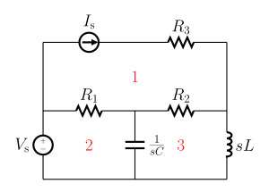
I have reverted the change to svg diagrams. It is not really essential that they are changed, the png format is perfectly adequate for what is needed here. I find the new diagrams lack the clarity of the old ones. In addition there are some errors - current sources are shown as capacitors in two places. SpinningSpark 12:40, 23 November 2012 (UTC)Reply
I've fixed the errors with the current sources. Can you elaborate a bit on how you feel the new diagrams are less clear? I find them to be much easier to read than the old. – GorillaWarfare(talk) 17:21, 23 November 2012 (UTC)Reply
The errors certainly need correcting. As for the format - this is clearer and better formatted than this? Really? The font on the existing PNG is so tiny as to flummox my eyes when it comes to readability (I'm fairly sure, but not completely sure, that that character is an s) while the size of the image makes any attempt to go "I'm not quite sure about this bit, lets look closer" a wasted effort. Ironholds (talk) 17:22, 23 November 2012 (UTC)Reply
I agree that the formatting of variable names is done better in the svg versions, following proper mathematical conventions, but the italic font is much harder to read in a thumbnail. To match the readability of the original it would need to be in a larger point size and (possibly) bolded.
The inductors are so small in the thumbnail that they are not recognisable as such, even if one knows what the symbol for an inductor is supposed to look like.
The symbol for an inductor has been gratuitously changed. In other areas (date format, spelling systems) that sort of change is strongly frowned on when done without consensus. I am not against the curly inductor symbol per se, I quite like it and have used it in some of my own diagrams, but it does seem perverse to change it in an article that is already using the more modern symbol.
While on the inductor (and I know this was a fault of the original diagrams as well) the s should precede the L otherwise it can easily be mistaken for a subscript, especially as the diaagrams really do use s as a subscript.
I'm not sure that the greying out of the loop currents and the mesh annotation is a good idea. After all, those are the most significant features of the diagrams in terms of this article. Perhaps a different colour would be a better scheme.
I am also not a fan of the "squaring off" of the mesh current arrows, although I concede this may just be personal preference.
In short, I am not opposed to svg diagrams, but there should be some visible benefit before changing, and these could be a lot better. SpinningSpark 22:13, 23 November 2012 (UTC)Reply
Your points seem valid. I'll make some changes when I get a minute. – GorillaWarfare(talk) 02:50, 24 November 2012 (UTC)Reply
I've adjusted the diagram for the first example. I've posted it here so you can see what it will look like on the page at that size. Thoughts? If you think it looks good, I'll make the same changes to the other three. – GorillaWarfare(talk) 02:38, 25 November 2012 (UTC)Reply
That looks good except that I would say the inductor still looks too small relative to the other components. It needs enlarging, and reducing the number of loops will help stop it becoming too long after enlargement. I believe the standard number of loops is four. SpinningSpark 09:38, 25 November 2012 (UTC)Reply
Why have you taken the italics off the vsariable names? That was actually correct and an improvement. SpinningSpark 09:43, 25 November 2012 (UTC)Reply
I have just changed all the lower case currents in the math markup to match the diagrams. The equations were mixing upper case (phasor) voltages with lower case (instantaneous) currents, which is incorrect. SpinningSpark 09:54, 25 November 2012 (UTC)Reply
Ah, I misread your mention of the italic font being difficult to read as a suggestion to change it. I agree, though, I prefer the italics. I've again updated it with your suggestions. What do you think? – GorillaWarfare(talk) 20:54, 25 November 2012 (UTC)Reply
That works for me, I'd be happy for that to go in the article. Just one little niggle, the subscript "s" in and should not be italicised as it is not a variable or index. SpinningSpark 22:12, 25 November 2012 (UTC)Reply
Alrighty, I've updated that and the three others. Do they look okay? – GorillaWarfare(talk) 23:04, 25 November 2012 (UTC)Reply
We need to consistently use upper case or lower case for currents and voltages. See my note above. I suggest upper case for everything, as on the original diagrams. SpinningSpark 23:32, 25 November 2012 (UTC)Reply


