A lock is a device used for raising and lowering boats, ships and other watercraft between stretches of water of different levels on river and canal waterways. The distinguishing feature of a lock is a fixed chamber in which the water level can be varied; whereas in a caisson lock, a boat lift, or on a canal inclined plane, it is the chamber itself (usually then called a caisson) that rises and falls.[1]


.jpg)
Locks are used to make a river more easily navigable, or to allow a canal to cross land that is not level.[2] Later canals used more and larger locks to allow a more direct route to be taken.
Pound lock edit

A pound lock is most commonly used on canals and rivers today.[3] A pound lock has a chamber with gates at both ends that control the level of water in the pound. In contrast, an earlier design with a single gate was known as a flash lock.[4]
Pound locks were first used in China during the Song Dynasty (960–1279 CE), having been pioneered by the Song politician and naval engineer Qiao Weiyue in 984.[5] They replaced earlier double slipways that had caused trouble and are mentioned by the Chinese polymath Shen Kuo (1031–1095) in his book Dream Pool Essays (published in 1088),[6] and fully described in the Chinese historical text Song Shi (compiled in 1345):[7]
The distance between the two locks was rather more than 50 paces, and the whole space was covered with a great roof like a shed. The gates were 'hanging gates'; when they were closed the water accumulated like a tide until the required level was reached, and then when the time came it was allowed to flow out.
The water level could differ by 4 or 5 feet (1.2 or 1.5 m) at each lock and in the Grand Canal the level was raised in this way by 138 feet (42 m).[7]
In medieval Europe a sort of pound lock was built in 1373 at Vreeswijk, Netherlands.[8] This pound lock serviced many ships at once in a large basin. Yet the first true pound lock was built in 1396 at Damme near Bruges, Belgium.[8] The Italian Bertola da Novate (c. 1410–1475) constructed 18 pound locks on the Naviglio di Bereguardo (part of the Milan canal system sponsored by Francesco Sforza) between 1452 and 1458.[9]
Basic construction and operation edit

| For a boat going upstream: | 
|
For a boat going downstream: | ||
|---|---|---|---|---|
| 1–2. | The boat enters the lock. | 8–9. | The boat enters the lock. | |
| 3. | The lower gates are closed. | 10. | The upper gates are closed. | |
| 4–5. | The lock is filled with water from upstream. | 11–12. | The lock is emptied by draining its water downstream. | |
| 6. | The upper gates are opened. | 13. | The lower gates are opened. | |
| 7. | The boat exits the lock. | 14. | The boat exits the lock. | |
All pound locks have three elements:
- A watertight chamber connecting the upper and lower canals, and large enough to enclose one or more boats. The position of the chamber is fixed, but its water level can vary.
- A gate (often a pair of "pointing" half-gates) at each end of the chamber. A gate is opened to allow a boat to enter or leave the chamber; when closed, the gate is watertight.
- A set of lock gear to empty or fill the chamber as required. This is usually a simple valve (traditionally, a flat panel (paddle) lifted by manually winding a rack and pinion mechanism) which allows water to drain into or out of the chamber.[10] Larger locks may use pumps.[11]
The principle of operating a lock is simple. For instance, if a boat travelling downstream finds the lock already full of water:
- The entrance gates are opened and the boat moves in.
- The entrance gates are closed.
- A valve is opened, this lowers the boat by draining water from the chamber.
- The exit gates are opened and the boat moves out.[10]
If the lock were empty, the boat would have had to wait 5 to 10 minutes while the lock was filled. For a boat travelling upstream, the process is reversed; the boat enters the empty lock, and then the chamber is filled by opening a valve that allows water to enter the chamber from the upper level. The whole operation will usually take between 10 and 20 minutes, depending on the size of the lock and whether the water in the lock was originally set at the boat's level.[10]
Boaters approaching a lock are usually pleased to meet another boat coming towards them, because this boat will have just exited the lock on their level and therefore set the lock in their favour – saving about 5 to 10 minutes. However, this is not true for staircase locks, where it is quicker for boats to go through in convoy, and it also uses less water.[12]

1–3. Boat enters 'empty' lock
4. Bottom gates are closed, bottom paddles closed, top paddles opened, lock starts to fill
5. Lock is filling with water, lifting boat to the higher level
Details and terminology edit
Rise edit
The rise is the change in water-level in the lock. The two deepest locks on the English canal system are Bath deep lock[13][14] on the Kennet and Avon Canal and Tuel Lane Lock on the Rochdale Canal, which both have a rise of nearly 20 feet (6.1 m). Both locks are amalgamations of two separate locks, which were combined when the canals were restored to accommodate changes in road crossings. By comparison, the Carrapatelo and Valeira locks on the Douro river in Portugal, which are 279 feet (85 m) long and 39 feet (12 m) wide, have maximum lifts of 115 and 108 feet (35 and 33 m) respectively.[15] The two Ardnacrusha locks near Limerick on the Shannon navigation in Ireland have a rise of 100 feet (30 m). The upper chamber rises 60 feet (18 m) and is connected to the lower chamber by a tunnel, which when descending does not become visible until the chamber is nearly empty.[16]
Pound edit
A pound is the level stretch of water between two locks (also known as a reach).[17]
Cill edit
The cill, also spelled sill, is a narrow horizontal ledge protruding a short way into the chamber from below the upper gates. Allowing the rear of the boat to "hang" on the cill is the main danger when descending a lock, and the position of the forward edge of the cill is usually marked on the lock side by a white line. The edge of the cill is usually curved, protruding less in the center than at the edges. In some locks, there is a piece of oak about 9 in (23 cm) thick which protects the solid part of the lock cill. On the Oxford Canal it is called a babbie; on the Grand Union Canal it is referred to as the cill bumper. Some canal operation authorities, primarily in the United States and Canada, call the ledge a miter sill (mitre sill in Canada).[18]
Photo gallery edit
-
 The cill exposed in the deep Pont de Flandre lock on the Canal Saint-Denis, Paris
 -
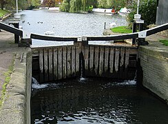 Top gate of a lock, showing the balance beams and paddle winding gear
 -
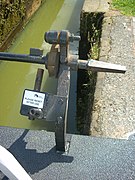
 200-year-old paddle gear on the Wiener Neustädter Kanal, Austria
 -
 Water conservation gear on the Birmingham Canal Navigations
 -
 Lock gate controls on a canal


Gates edit
Gates are the watertight doors which seal off the chamber from the upper and lower pounds. Each end of the chamber is equipped with a gate, or pair of half-gates, traditionally made of oak or elm but now usually made of steel). The most common arrangement, usually called miter gates, was invented by Leonardo da Vinci sometime around the late 15th century.[19]
Paddle edit
On the old Erie Canal, there was a danger of injury when operating the paddles: water, on reaching a certain position, would push the paddles with a force which could tear the windlass (or handle) out of one's hands, or if one was standing in the wrong place, could knock one into the canal, leading to injuries and drownings.[20]
Windlass ("lock key") edit

On the Chesapeake and Ohio Canal, the lockkeepers were required to remove the windlasses from all lock paddles at night, to prevent unauthorized use.[21]
Swell or swelling edit
A swell was caused by opening suddenly the paddle valves in the lock gates, or when emptying a lock.[22] To help boats traveling downstream exit a lock, the locksman would sometimes open the paddles to create a swell, which would help "flush" the boat out of the lock. A boatsman might ask for a back swell, that is, to open and shut the paddles a few times to create some waves, to help him get off the bank where he was stuck.[23] If boats ran aground (from being overloaded) they sometimes asked passing crews to tell the upstream lock to give them an extra heavy swell, which consisted of opening all the paddles on the lock gate, creating a surge that affected the whole pound below.[24]
On the Erie Canal, some loaded boats needed a swell to get out of the lock. Particularly lumber boats, being top heavy, would list to one side and get stuck in the lock, and needed a swell to get them out. Some lockkeepers would give a swell to anyone to help them on the way, but some would ask for money for the swell.[22]
The Erie Canal management did not like swelling for two reasons. First, it used too much water lowering the water on the pound above sometimes causing boats to run aground. In addition, it raised the water level on the pound below, causing some boats to strike bridges or get stuck.[22]
Snubbing posts edit

On horse-drawn and mule-drawn canals, snubbing posts were used to slow or stop a boat in the lock. A 200-ton boat moving at a few miles an hour could destroy the lock gate. To prevent this, a rope was wound around the snubbing post as the boat entered the lock. Pulling on the rope slowed the boat, due to the friction of the rope against the post.[25] A rope 2+1⁄2 inches (6.4 cm) in diameter and about 60 feet (18 meters) long was typically used on the Erie Canal to snub a boat in a lock.[26]
One incident, which took place in June 1873 on the Chesapeake and Ohio Canal, involved the boat the Henry C. Flagg and its drunk captain. That boat was already leaking; the crew, having partially pumped the water out, entered Lock 74, moving in front of another boat. Because they failed to snub the boat, it crashed into and knocked out the downstream gates. The outrush of water from the lock caused the upstream gates to slam shut, breaking them also, and sending a cascade of water over the boat, sinking it. This suspended navigation on the canal for 48 hours until the lock gates could be replaced and the boat removed from the lock.[27]
Variations edit
Composite locks edit
To economise, especially where good stone would be prohibitively expensive or difficult to obtain, composite locks were made, i.e. they were constructed using rubble or inferior stone, dressing the inside walls of the lock with wood, so as not to abrade the boats. This was done, for instance, on the Chesapeake and Ohio Canal with the locks near the Paw Paw Tunnel.[28] and also the Chenango Canal[29]
Powered operation edit
On large modern canals, especially very large ones such as ship canals, the gates and paddles are too large to be hand operated, and are operated by hydraulic or electrical equipment. On the Caledonian Canal the lock gates were operated by man-powered capstans, one connected by chains to open the gate and another to draw it closed. By 1968 these had been replaced by hydraulic power acting through steel rams.[30]
Fish ladders edit
The construction of locks (or weirs and dams) on rivers obstructs the passage of fish. Some fish such as lampreys, trout and salmon go upstream to spawn. Measures such as a fish ladder are often taken to counteract this. Navigation locks have also potential to be operated as fishways to provide increased access for a range of biota.[31]
Special cases edit
Doubled, paired or twinned locks edit

Locks can be built side by side on the same waterway. This is variously called doubling, pairing, or twinning. The Panama Canal has three sets of double locks. Doubling gives advantages in speed, avoiding hold-ups at busy times and increasing the chance of a boat finding a lock set in its favour. The Belgian company SBE Engineering worked on this project. There can also be water savings: the locks may be of different sizes, so that a small boat does not need to empty a large lock; or each lock may be able to act as a side pond (water-saving basin) for the other. In this latter case, the word used is usually "twinned": here indicating the possibility of saving water by synchronising the operation of the chambers so that some water from the emptying chamber helps to fill the other. This facility has long been withdrawn on the English canals, although the disused paddle gear can sometimes be seen, as at Hillmorton on the Oxford Canal. Elsewhere they are still in use; a pair of twinned locks was opened in 2014 on the Dortmund–Ems Canal near Münster, Germany.[32]
The once-famous staircase at Lockport, New York, was also a doubled set of locks. Five twinned locks allowed east- and west-bound boats to climb or descend the 60 feet (18 m) Niagara Escarpment, a considerable engineering feat in the nineteenth century. While Lockport today has two large steel locks, half of the old twin stair acts as an emergency spillway and can still be seen, with the original lock gates having been restored in early 2016.[33]
Stop locks edit
When variable conditions meant that a higher water level in the new canal could not be guaranteed, then the older company would also build a stop lock (under its own control, with gates pointing towards its own canal) which could be closed when the new canal was low. This resulted in a sequential pair of locks, with gates pointing in opposite directions: one example was at Hall Green near Kidsgrove, where the southern terminus of the Macclesfield Canal joined the Hall Green Branch of the earlier Trent and Mersey Canal. The four gate stop lock near Kings Norton Junction, between the Stratford-upon-Avon Canal and the Worcester and Birmingham Canal was replaced in 1914 by a pair of guillotine lock gates which stopped the water flow regardless of which canal was higher. These gates have been permanently open since nationalisation.[34]
Round locks edit

The best known example of a round lock is the Agde Round Lock on the Canal du Midi in France. This serves as a lock on the main line of the canal and allows access to the Hérault River.[35]
A second French round lock can be found in the form of the now-disused Écluse des Lorraines, connecting the Canal latéral à la Loire with the River Allier.[36]
Drop locks edit

A drop lock can consist of two conventional lock chambers leading to a sump pound, or a single long chamber incorporating the sump – although the term properly applies only to the second case. As the pounds at either end of the structure are at the same height, the lock can only be emptied either by allowing water to run to waste from the sump to a lower stream or drain, or (less wastefully) by pumping water back up to the canal. Particularly in the two-chamber type, there would be a need for a bypass culvert, to allow water to move along the interrupted pound and so supply locks further down the canal. In the case of the single-chamber type, this can be achieved by keeping the lock full and leaving the gates open while not in use.[37]
While the concept has been suggested in a number of cases, the only example in the world of a drop lock that has actually been constructed is at Dalmuir on the Forth and Clyde Canal in Scotland.[38] This lock, of the single-chamber type, was incorporated during the restoration of the canal, to allow the replacement of a swing bridge (on a busy A road) by a fixed bridge, and so answer criticisms that the restoration of the canal would cause frequent interruptions of the heavy road traffic. It can be emptied by pumping – but as this uses a lot of electricity the method used when water supplies are adequate is to drain the lock to a nearby burn.[39]
Very large locks edit


Lock and Dam No. 6
In 2016 the Kieldrecht Lock in the Port of Antwerp in Belgium took over the title of the world's largest lock from the Berendrecht Lock in the same port and still has the title for largest volume. In 2022 the IJmuiden sea lock serving the Port of Amsterdam became the world's largest lock in dimensions. The lock is 500 m (1,600 ft) long, 70 m (230 ft) wide and has sliding lock gates creating a usable depth of 18 m (59 ft). The size of locks cannot be compared without considering the difference in water level that they are designed to operate under. For example, the Bollène lock on the River Rhône has a fall of at least 23 m (75 ft), the Leerstetten, Eckersmühlen and Hilpoltstein locks on the Rhine–Main–Danube Canal have a fall of 24.67 m (80.9 ft), each and the Oskemen Lock on the Irtysh River in Kazakhstan has a drop of 42 m (138 ft).[40] [41][42]
History and development edit
Pound lock edit

The natural extension of the flash lock, or staunch, was to provide an upper gate (or pair of gates) to form an intermediate "pound" which was all that need be emptied when a boat passed through. This type of lock, called a pound lock was known in Imperial China and ancient Europe[43] and was used by Greek engineers in the Canal of the Pharaohs under Ptolemy II (284 to 246 BC), when engineers solved the problem of overcoming the difference in height through canal locks.[44][45][46][47]
Pound locks were first used in medieval China during the Song Dynasty (960–1279 CE). The Songshi or History of the Song Dynasty, volume 307, biography 66, records how Qiao Weiyue, a high-ranking tax administrator, was frustrated at the frequent losses incurred when his grain barges were wrecked on the West River near Huai'an in Jiangsu. The soldiers at one double slipway, he discovered, had plotted with bandits to wreck heavy imperial barges so that they could steal the spilled grain. In 984 Qiao installed a pair of sluice-gates two hundred and fifty feet apart, the entire structure roofed over like a building. By siting two staunch gates so close to one another, Qiao had created a short stretch of canal, effectively a pound-lock, filled from the canal above by raising individual wooden baulks in the top gate and emptied into the canal below by lowering baulks in the top gate and raising ones in the lower.[7]

Turf-sided lock edit
A turf-sided lock is an early form of canal lock design that uses earth banks to form the lock chamber, subsequently attracting grasses and other vegetation, instead of the now more familiar and widespread brick, stone, or concrete lock wall constructions. This early lock design was most often used on river navigations in the early 18th century before the advent of canals in Britain. The sides of the turf-lock are sloping so, when full, the lock is quite wide. Consequently, this type of lock needs more water to operate than vertical-sided brick- or stone-walled locks. On British canals and waterways most turf-sided locks have been subsequently rebuilt in brick or stone, and so only a few good examples survive, such as at Garston Lock, and Monkey Marsh Lock, on the Kennet and Avon Canal.[48]
Use of water edit
Water saving basins edit
On English canals, these reservoirs are called "side ponds". The Droitwich Canal, reopened in 2011, has a flight of three locks at Hanbury which all have operational side ponds.[49]
Alternatives edit
Inclined plane edit
There are no working waterway inclined planes in the UK at the moment, but the remains of a famous one can be seen at Foxton in Leicestershire on the Leicester arm of the Grand Union Canal. The plane enabled wide-beam boats to bypass the flight of ten narrow locks, but failure to make improvements at the other end of the arm and high running costs led to its early demise.[50] There are plans to restore it, and some funding has been obtained.[51]
Caisson lock edit

Around 1800 the use of caisson locks was proposed by Robert Weldon[52] for the Somerset Coal Canal in England. In this underwater lift, the chamber was 80 ft (24.4 m) long and 60 ft (18.3 m) deep and contained a completely enclosed wooden box big enough to take a barge. This box moved up and down in the 60 ft (18.3 m) deep pool of water. Apart from inevitable leakage, the water never left the chamber, and using the lock wasted no water. Instead, the boat entered the box and was sealed in by the door closing behind it, and the box itself was moved up or down through the water. When the box was at the bottom of the chamber, it was under almost 60 feet (18.3 m) of water – at a pressure of three atm (304 kPa; 44.1 psi), in total. One of these "locks" was built and demonstrated to the Prince Regent (later George IV), but it had various engineering problems and the design was not put into use on the Coal Canal.[53][54]
Hydro-pneumatic canal lift edit
Possibly inspired by Weldon's caisson lock, William Congreve in 1813 patented a "hydro-pneumatic double balance lock" in which two adjacent locks containing pneumatic caissons could be raised and lowered in counterbalance by the movement of compressed air from one caisson to the other. In about 1817 the Regents Canal Company built one of these locks at the site of the present-day Camden Lock, north London. Here the motivation was, again, water supply problems. The company insisted on various modifications to Congreve's design; the resulting installation proved to be unsatisfactory, and was soon replaced by conventional locks.[55][56]
Shaft lock edit

Looking superficially similar to the caisson lock is the shaft lock. Shaft locks consist of a deep shaft with conventional upper gates. The lower gates are reached through a short tunnel. The gates only close off this approach tunnel so do not have to reach the full height of the lock. Notable examples have been built at Saint Denis (Paris, France), Horin (near Melnik, Czech Republic) and Anderten (Hannover Germany).[57] The shaft lock at Minden 52°18′23″N 8°55′11″E / 52.30639°N 8.91972°E has a fall of 12.7 metres (42 ft) and has eight tanks linked in pairs to the lock chamber.[58] As the lock is emptied water is run into each chamber in turn, for filling the water is released from the chambers thus saving the waste of a complete lockfull of water. An earlier attempt at a shaft lock had been made at Trollhättan in Sweden on the line of the present Göta canal. The fall would have been 16 metres (52 ft), astonishing in 1749. However the approach tunnel proved to be unusable in times of flood and the shaft lock was replaced by a 2-rise staircase in 1768.[59]
Diagonal lock edit

This is similar to a shaft lock, but having the shaft built on an incline. Boats are moored to floating bollards which guide them along the shaft as it fills or empties. The "Diagonal Lock Advisory Group" has identified several sites in Britain where the new design could be installed, either on new waterways or canals under restoration.[60] Projects under consideration include the restoration of the Lancaster Canal to Kendal and the proposed new branch of the Grand Union Canal between Bedford and Milton Keynes.
See also edit
References edit
- ^ "Canals and inland waterways - Locks, Navigation, Engineering | Britannica". www.britannica.com. Retrieved 2023-10-05.
- ^ "Different types of locks". canalrivertrust.org.uk. Retrieved 2023-10-05.
- ^ Newcomb, Tim (13 December 2016). "7 of the World's Most Impressive Canal Locks". Popular Mechanics.
- ^ Needham, Joseph; Lu, Gwei-Djen; Wang, Ling (1971). "Civil Engineering and Nautics". Science and Civilisation in China. Vol. 4:3. Cambridge: Cambridge University Press. p. 352.
- ^ Needham, Volume 4, Part 3, 350-351.
- ^ Needham, Volume 4, Part 3, 351–52.
- ^ a b c Needham, Volume 4, Part 3, 351.
- ^ a b Needham, Volume 4, Part 3, 357.
- ^ Needham, Volume 4, Part 3, 358.
- ^ a b c Cumberlidge 2009, p. 23.
- ^ "How do canal locks work?". ABC Boat Hire. Archived from the original on 2 June 2023.
- ^ "Staircase Canal Locks". Droitwich Canals. Archived from the original on 4 January 2022.
- ^ "Second Lock". Images of England. Archived from the original on 16 November 2007. Retrieved 4 September 2006.
- ^ Allsop, Niall (1987). The Kennet & Avon Canal. Bath: Millstream Book. ISBN 0-948975-15-6.
- ^ "Final Report of the International Commission for the Study of Locks". Google Books. Retrieved 20 May 2013.
- ^ "The ESB lock at Ardnacrusha". Irish Waterways History. 22 July 2009. Retrieved 2012-03-23.
- ^ "Reach". Oxford English Dictionary (Second ed.). Oxford, England: Oxford University Press. 1989.
...the portion of a canal between two locks, having a uniform level
- ^ Merriam-Webster Dictionary, definition of miter sill, Retrieved Jan. 28, 2015.
- ^ "Canal Lock". Encyclopedia.com. 2018-05-17. Retrieved 2023-08-13.
- ^ Garrity, Richard (1977). Canal Boatman My Life on Upstate Waterways. Syracuse, NY: Syracuse University Press. p. 38. ISBN 0-8156-0139-5.
- ^ Unrau p. 336
- ^ a b c Garrity, Richard (1977). Canal Boatman My Life on Upstate Waterways. Syracuse, NY: Syracuse University Press. p. 39. ISBN 0-8156-0139-5.
- ^ Kytle, Elizabeth. Home on the Canal. Seven Locks Press, 1983. p. 207
- ^ Garrity, Richard. p. 40
- ^ Kytle, Elizabeth. Home on the Canal. 1996. ISBN 0801853281, p. 133
- ^ Garrity, Richard. p. 41
- ^ "p. 812" (PDF). nps.gov. Retrieved 21 September 2018.
- ^ Kytle, Elizabeth. Home on the Canal. Seven Locks Press, 1983, ISBN 978-0-932020-13-0 pp. 71–72
- ^ Bearss, Edwin C. (1968). "The Composite Locks" (PDF). US Department of the Interior, National Park Service. p. 15. Archived from the original (PDF) on July 3, 2007. Retrieved May 24, 2013.
- ^ Cameron, A.D. (2005). "10 Working the canal in the 1820s". The Caledonian Canal (4 ed.). Edinburgh: Birlinn. ISBN 9781841584034.
- ^ Silva, S.; Lowry, M.; Macaya-Solis, C.; Byatt, B.; Lucas, M.C. (2017). "Can navigation locks be used to help migratory fishes with poor swimming performance pass tidal barrages? A test with lampreys". Ecological Engineering. 102: 291–302. doi:10.1016/J.ECOLENG.2017.02.027. S2CID 55266451.
- ^ "Zwillingsschleuse Münster" (in German).
- ^ "Governor Cuomo Announces Funding For Restoration of Lockport Locks". ny.gov. 17 August 2015. Retrieved 21 September 2018.
- ^ Birmingham's Canals, Ray Shill, 1999, 2002, ISBN 0-7509-2077-7
- ^ "Canal du Midi". Afloat in France. grehanman guides. Retrieved 2010-11-23.
- ^ "Canal lateral a la Loire". Afloat in France. grehanman guides. Retrieved 2010-11-24.
- ^ "Dalmuir Drop Lock". Retrieved 22 October 2007.
- ^ voltimum (11 December 2002). "Mitsubishi helps breath new life into important canal routes". Retrieved 23 October 2007.
- ^ "Clydebank Drop Lock". Gentles.info. Retrieved 2011-08-05.
- ^ "Latest". Waterways World. Archived from the original on 2011-07-26. Retrieved 2011-08-05.
- ^ "Officiële opening van de grootste zeesluis ter wereld". Port of Amsterdam. 26 January 2022. Retrieved 2022-01-22.
- ^ van den Buijs, Dennis (26 January 2022). ""Nederlanders kunnen niet rekenen": waarom Antwerpen en niet Amsterdam de grootste zeesluis ter wereld heeft". VRT. Retrieved 30 March 2022.
- ^ Moore, Frank Gardner (1950). "Three Canal Projects, Roman and Byzantine". American Journal of Archaeology. 54 (2): 97–111 (99). doi:10.2307/500198. JSTOR 500198. S2CID 191374346.
- ^ Rappoport 1904, pp. 250-253
- ^ Moore 1950, pp. 99–101
- ^ Froriep 1986, p. 46
- ^ Schörner 2000, pp. 33–35
- ^ "British Waterways 'Waterscape' website". Archived from the original on 3 April 2012. Retrieved 11 January 2011.
- ^ Smithett, Robin (April 2012). "A bit on the side". Waterways World. ISSN 0309-1422.
- ^ Nicholson Waterways Guide, Volume 3, Harper Collins Publishers, ISBN 0-00-713666-8
- ^ "Foxton Inclined Plane Trust: Restoration". Fipt.org.uk. Archived from the original on 2011-09-27. Retrieved 2011-08-05.
- ^ Robert Weldon
- ^ "The Somerset Coal Canal". Bath Royal Literary and Scientific Institution. Archived from the original on 14 November 2006. Retrieved 6 October 2006.
- ^ "History of the Caisson Lock On the Somersetshire Coal Canal". The Somersetshire Coal Canal (Society). Archived from the original on 11 October 2006. Retrieved 6 October 2006.
- ^ "Congreve's Hydro-Pneumatic Canal Lift – A Humbug!". London Canals. Archived from the original on 27 September 2013. Retrieved 25 September 2013.
- ^ Faulkner, Alan (2005): The Regent's Canal: London's Hidden Waterway. Waterways World Ltd. ISBN 1-870002-59-8.
- ^ Hughes, Stephen (ed.). "The International Canal Monuments List" (PDF). ICOMOS (the International Council on Monuments and Sites). Archived from the original (PDF) on 2013-08-10. Retrieved 2015-09-06.
- ^ Hadfield, Charles (1986). World Canals: Inland Navigation Past and Present. David & Charles. p. 162. ISBN 0-7153-8555-0.
- ^ Hadfield (1986) p. 55.
- ^ Fogarty, Terry (2008). "Diagonal Lock – Overview". Archived from the original on 15 February 2017. Retrieved 6 November 2016.
Bibliography edit
- Cumberlidge, Jane (2009). Inland Waterways of Great Britain (8th Ed.). Imray Laurie Norie and Wilson. ISBN 978-1-84623-010-3.
External links edit
- Deepest Canal Locks in England
- Interactive simulation of lock operation – this demonstration shows guillotine-type gates for clarity
- Interactive lock game for students with single and double flight locks and lesson plans
- Video footage of the unique Drop Lock at Dalmuir on the Forth & Clyde Canal