
Wireless energy transfer or Wireless power is the transmission of electrical energy from a power source to an electrical load without interconnecting wires. Wireless transmission is useful in cases where interconnecting wires are inconvenient, hazardous, or impossible. A form of wireless power exists today,[1] in that radio transmissions are carried by the energy of electromagnetic space waves to radio receivers.[2] The problem of wireless power differs from that of wireless telecommunications, where the signal-to-noise ratio (SNR) or the percentage of the transmitted energy received becomes critical only if it is too low for the signal to be demodulated. With wireless power the system's efficiency is the more significant parameter. A large part of the energy sent out by the generating plant must arrive at the receiver or receivers to make the system economical.[2]
The most common form of wireless power transmission is carried out using inductive coupling followed by resonant inductive coupling. Other methods include electromagnetic radiation in the form of microwaves and lasers. While practical industrial wireless power transmission by electromagnetic radiation is only a remote possibility[3][2] designs for such systems are presently being considered.[4]
Electric energy transfer edit
In electronics and telecommunication, coupling is the desirable or undesirable transfer of energy from one medium, such as a metallic wire or an optical fiber, to another medium, including fortuitous transfer.
Coupling is also the transfer of power from one circuit segment to another. For example, electrical energy is transferred from a power source to an electrical load by means of conductive coupling, which may be either resistive or hard-wire. An AC potential may be transferred from one circuit segment to another having a DC potential by use of a capacitor. Electrical energy may be efficiently transferred from one circuit segmant to another segment with different impedance by use of a transformer. This is known as impedance matching. These are examples of electrostatic and electrodynamic inductive coupling.
Types of coupling edit
Electrical conduction:
Electromagnetic induction:
- electrodynamic commonly called inductive coupling, also magnetic coupling
- electrostatic commonly called capacitive coupling
- evanescent wave coupling
Electromagnetic radiation:
- radio wireless telecommunications
- electromagnetic interference (EMI), sometimes called radio frequency interference (RFI), is unwanted coupling. Electromagnetic compatibility (EMC) requires techniques to avoid such unwanted coupling, such as electromagnetic shielding.
- Other kinds of energy coupling:
- acoustic coupling with an acoustic coupler
See also edit
- antenna noise temperature
- coupling loss
- directional coupler
- equilibrium length
- fiber-optic coupling
- loading coil
- shield
- list of electronics topics
- AC Coupling
- impedance matching
- impedance bridging
- decoupling
Electric energy transfer edit
An electric current flowing through a conductor carries electrical energy. When an electric current passes through a circuit there is an electric field in the dielectric surrounding the conductor; magnetic field lines around the conductor and lines of electric force radially about the conductor.[5]
In a direct current circuit, if the current is continuous, the fields are constant; there is a condition of stress in the space surrounding the conductor, which represents stored electric and magnetic energy, just as a compressd spring or a moving mass represents stored energy. In an alternating current circuit, the fields also alternate; that is, with every half wave of current and of voltage, the magnetic and the electric field start at the conductor and run outwards into space with the velocity of light.[6] Where these alternating fields impinge on another conductor a voltage and a current are induced.[5]
Any change in the electrical conditions of the circuit, whether internal[7] or external[8] involves a readjustment of the stored magnetic and electric field energy of the circuit, that is, a so-called transient. A transient is of the general character of a condenser discharge through an inductive circuit. The phenomenon of the condenser discharge through an inductive circuit therefore is of the greatest importance to the engineer, as the foremost cause of high-voltage and high-frequency troubles in electric circuits.[9]
Electromagnetic induction is proportional to the intensity of the current and voltage in the conductor which produces the fields and to the frequency. The higher the frequency the more intense the induction effect. Energy is transferred from a conductor that produces the fields (the primary) to any conductor on which the fields impinge (the secondary). Part of the energy of the primary conductor passes inductively across space into secondary conductor and the energy decreases rapidly along the primary conductor. A high frequency current does not pass for long distances along a conductor but rapidly transfers its energy by induction to adjacent conductors. Higher induction resulting from the higher frequency is the explanation of the apparent difference in the propagation of high frequency disturbances from the propagation of the low frequency power of alternating current systems. The higher the frequency the more preponderant become the inductive effects that transfer energy from circuit to circuit across space. The more rapidly the energy decreases and the current dies out along the circuit, the more local is the phenomenon.[5]
The flow of electric energy thus comprises phenomena inside of the conductor[10] and phenomena in the space outside of the conductor—the electric field—which, in a continuous current circuit, is a condition of steady magnetic and dielectric stress, and in an alternating current circuit is alternating, that is, an electric wave launched by the conductor[5] to become far-field electromagnetic radiation traveling through space with the velocity of light.
In electric power transmission and distribution, the phenomena inside of the conductor are of main importance, and the electric field of the conductor is usually observed only incidentally.[11] Inversely, in the use of electric power for radio telecommunications it is only the electric and magnetic fields outside of the conductor, that is electromagnetic radiation, which is of importance in transmitting the message. The phenomenon in the conductor, the current in the launching structure, is not used.[5]
The electric charge displacement in the conductor produces a magnetic field and resultant lines of electric force. The magnetic field is a maximum in the direction concentric, or approximately so, to the conductor. That is, a ferromagnetic body[12] tends to set itself in a direction at right angles to the conductor. The electric field has a maximum in a direction radial, or approximately so, to the conductor. The electric field component tends in a direction radial to the conductor and dielectric bodies may be attracted or repelled radially to the conductor. [13]
The electric field of a circuit over which energy flows has three main axes at right angles with each other:
- The magnetic field, concentric with the conductor.
- The lines of electric force, radial to the conductor.
- The power gradient, parallel to the conductor.
Where the electric circuit consists of several conductors, the electric fields of the conductors superimpose upon each other, and the resultant magnetic field lines and lines of electric force are not concentric and radial respectively, except approximately in the immediate neighborhood of the conductor. Between parallel conductors they are conjugate of circles. Neither the power consumption in the conductor, nor the magnetic field, nor the electric field, are proportional to the flow of energy through the circuit. However, the product of the intensity of the magnetic field and the intensity of the electric field is proportional to the flow of energy or the power, and the power is therefore resolved into a product of the two components i and e, which are chosen proportional respectively to the intensity of the magnetic field and of the electric field. The component called the current is defined as that factor of the electric power which is proportional to the magnetic field, and the other component, called the voltage, is defined as that factor of the electric power which is proportional to the electric field.[13]
In radio telecommunications the electric field of the transmit antenna propagates through space as a radio wave and impinges upon the receive antenna where it is observed by its magnetic and electric effect.[13] Radio waves, microwaves, infrared radiation, visible light, ultraviolet radiation, X rays and gamma rays are shown to be the same electromagnetic radiation phenomenon, differing one from the other only in frequency of vibration.[14][5]
Electromagnetic induction edit
Energy transfer by electromagnetic induction is usually magnetic but capacitive coupling can also be achieved.
Electrodynamic induction method edit
The electrodynamic induction wireless transmission technique is near field over distances up to about one-sixth of the wavelength used. Near field energy itself is non-radiative but some radiative losses do occur. In addition there are usually resistive losses. In one of its forms, electromagnetic induction is based on the principle of using a magnetic field to generate an electric current within a conductor coil. Current flowing through the primary coil creates a magnetic field which acts on a secondary coil within this field, thereby generating current within the (coupled) secondary coil. Coupling must be tight in order to achieve high efficiency. As the distance from the primary is increased, more and more of the magnetic field misses the secondary. Even over a relatively short range the induction method is grossly inefficient, wasting much of the transmitted energy.[15]
The action of an electrical transformer is the simplest instance of wireless power transmission. The primary and secondary circuits of a transformer are not directly connected. Energy transfer takes place by electromagnetic coupling through a process known as mutual induction. Principal functions are stepping the primary voltage either up or down and electrical isolation. Mobile phone and electric toothbrush battery chargers, and electrical power distribution transformers are examples of how this principle is used. Induction cookers use this method. The main drawback to this basic form of wireless transmission is short range. The receiver must be directly adjacent to the transmitter or induction unit in order to efficiently couple with it.
The application of resonance improves the situation somewhat. When resonant coupling is used the transmitter and receiver inductors are tuned to a mutual frequency and the drive current is modified from a sinusoidal to a nonsinusoidal transient waveform.[16] Pulse power transfer occurs over multiple cycles. In this way significant power may be transmitted over a distance of up to a few times the size of the transmitter. Such transmitting and receiving coils are usually single layer solenoids or flat spirals with series capacitors, which, in combination, allow the receiving element to be tuned to the transmitter frequency.
Common uses of resonance-enhanced electrodynamic induction are charging the batteries of portable devices such as laptop computers and cell phones, medical implants and electric vehicles.[17][18][19] A localized charging technique [20] selects the appropriate transmitting coil in a multilayer winding array structure.[21] Resonance is used in both the wireless charging pad (the transmitter circuit) and the receiver module (embedded in the load) to maximize energy transfer efficiency. This approach is suitable for universal wireless charging pads for portable electronics such as mobile phones. It has been adopted as part of the Qi wireless charging standard.
It is also used for powering devices having no batteries, such as RFID patches and contactless smartcards, and to couple electrical energy from the primary inductor to the helical resonator of Tesla coil wireless power transmitters.
Electrostatic induction method edit


Electrostatic or capacitive coupling is the passage of electrical energy through a dielectric. In practice it is an electric field gradient or differential capacitance between two or more insulated terminals, plates, electrodes, or nodes that are elevated over a conducting ground plane. The electric field is created by an alternating current of high potential and high frequency. The capacitance between fixed plates and the powered device form a voltage divider.
The electric energy transmitted through the atmosphere can be utilized by receiving devices. [29][30][31][32] Tesla demonstrated the illumination of wireless lamps by energy that was coupled to them through an alternating electric field.[33][34][35]
"Instead of depending on electrodynamic induction at a distance to light the tube . . . [the] ideal way of lighting a hall or room would . . . be to produce such a condition in it that an illuminating device could be moved and put anywhere, and that it is lighted, no matter where it is put and without being electrically connected to anything. I have been able to produce such a condition by creating in the room a powerful, rapidly alternating electrostatic field. For this purpose I suspend a sheet of metal a distance from the ceiling on insulating cords and connect it to one terminal of the induction coil, the other terminal being preferably connected to the ground. Or else I suspend two sheets . . . each sheet being connected with one of the terminals of the coil, and their size being carefully determined. An exhausted tube may then be carried in the hand anywhere between the sheets or placed anywhere, even a certain distance beyond them; it remains always luminous."[36]
The principle of electrostatic induction is applicable to the electrical conduction wireless transmission method.
“In some cases when small amounts of energy are required the high elevation of the terminals, and more particularly of the receiving-terminal D', may not be necessary, since, especially when the frequency of the currents is very high, a sufficient amount of energy may be collected at that terminal by electrostatic induction from the upper air strata, which are rendered conducting by the active terminal of the transmitter or through which the currents from the same are conveyed."[37]
Electromagnetic radiation edit

Far field methods achieve longer ranges, often multiple kilometer ranges, where the distance is much greater than the diameter of the device(s). The main reason for longer ranges with radio wave and optical devices is the fact that electromagnetic radiation in the far-field can be made to match the shape of the receiving area (using high directivity antennas or well-collimated Laser Beam) thereby delivering almost all emitted power at long ranges. The maximum directivity for antennas is physically limited by diffraction.
Beamed power, size, distance, and efficiency edit
The size of the components may be dictated by the distance from transmitter to receiver, the wavelength and the Rayleigh criterion or diffraction limit, used in standard radio frequency antenna design, which also applies to lasers. In addition to the Rayleigh criterion Airy's diffraction limit is also frequently used to determine an approximate spot size at an arbitrary distance from the aperture.
The Rayleigh criterion dictates that any radio wave, microwave or laser beam will spread and become weaker and diffuse over distance; the larger the transmitter antenna or laser aperture compared to the wavelength of radiation, the tighter the beam and the less it will spread as a function of distance (and vice versa). Smaller antennae also suffer from excessive losses due to side lobes. However, the concept of laser aperture considerably differs from an antenna. Typically, a laser aperture much larger than the wavelength induces multi-moded radiation and mostly collimators are used before emitted radiation couples into a fiber or into space.
Ultimately, beamwidth is physically determined by diffraction due to the dish size in relation to the wavelength of the electromagnetic radiation used to make the beam. Microwave power beaming can be more efficient than lasers, and is less prone to atmospheric attenuation caused by dust or water vapor losing atmosphere to vaporize the water in contact.
Then the power levels are calculated by combining the above parameters together, and adding in the gains and losses due to the antenna characteristics and the transparency and dispersion of the medium through which the radiation passes. That process is known as calculating a link budget.
Microwave method edit
Power transmission via radio waves can be made more directional, allowing longer distance power beaming, with shorter wavelengths of electromagnetic radiation, typically in the microwave range. A rectenna may be used to convert the microwave energy back into electricity. Rectenna conversion efficiencies exceeding 95% have been realized. Power beaming using microwaves has been proposed for the transmission of energy from orbiting solar power satellites to Earth and the beaming of power to spacecraft leaving orbit has been considered.[4][38]
Power beaming by microwaves has the difficulty that for most space applications the required aperture sizes are very large due to diffraction limiting antenna directionality. For example, the 1978 NASA Study of solar power satellites required a 1-km diameter transmitting antenna, and a 10 km diameter receiving rectenna, for a microwave beam at 2.45 GHz[citation needed]. These sizes can be somewhat decreased by using shorter wavelengths, although short wavelengths may have difficulties with atmospheric absorption and beam blockage by rain or water droplets. Because of the "thinned array curse," it is not possible to make a narrower beam by combining the beams of several smaller satellites.
For earthbound applications a large area 10 km diameter receiving array allows large total power levels to be used while operating at the low power density suggested for human electromagnetic exposure safety. A human safe power density of 1 mW/cm2 distributed across a 10 km diameter area corresponds to 750 megawatts total power level. This is the power level found in many modern electric power plants.
Following World War II, which saw the development of high-power microwave emitters known as cavity magnetrons, the idea of using microwaves to transmit power was researched. By 1964 a miniature helicopter propelled by microwave power had been demonstrated.[39]
Japanese researcher Hidetsugu Yagi also investigated wireless energy transmission using a directional array antenna that he designed. In February 1926, Yagi and Uda published their first paper on the tuned high-gain directional array now known as the Yagi antenna. While it did not prove to be particularly useful for power transmission, this beam antenna has been widely adopted throughout the broadcasting and wireless telecommunications industries due to its excellent performance characteristics.[40]
Wireless high power transmission using microwaves is well proven. Experiments in the tens of kilowatts have been performed at Goldstone in California in 1975[41][42][43] and more recently (1997) at Grand Bassin on Reunion Island.[44] These methods achieve distances on the order of a kilometer.
Laser method edit

In the case of electromagnetic radiation closer to visible region of spectrum (10s of microns (um) to 10s of nm), power can be transmitted by converting electricity into a laser beam that is then pointed at a solar cell receiver. This mechanism is generally known as "powerbeaming" because the power is beamed at a receiver that can convert it to usable electrical energy.
Advantages of laser based energy transfer compared with other wireless methods are:[45]
- collimated monochromatic wavefront propagation allows narrow beam cross-section area for energy transmission over large ranges.
- compact size of solid state lasers-photovoltaics semiconductor diodes fit into into small products.
- no radio-frequency interference to existing radio communication such as Wi-fi and cell phones.
- control of access; only receivers illuminated by the laser receive power.
Its drawbacks are:
- Conversion to light, such as with a laser, is inefficient
- Conversion back into electricity is inefficient, with photovoltaic cells achieving 40%-50% efficiency.[46] (Note that conversion efficiency is rather higher with monochromatic light than with insolation of solar panels).
- Atmospheric absorption causes losses.
- As with microwave beaming, this method requires a direct line of sight with the target.
The laser "powerbeaming" technology has been mostly explored in military weapons[47][48][49] and aerospace [50][51] applications and is now being developed for commercial and consumer electronics Low-Power applications. Wireless energy transfer system using laser for consumer space has to satisfy Laser safety requirements standardized under IEC 60825.
To develop an understanding of the trade-offs of Laser ("a special type of light wave"-based system):[52][53][54][55]
- Propagation of a laser beam [56][57][58] (on how Laser beam propagation is much less affected by diffraction limits)
- Coherence and the range limitation problem (on how spatial and spectral coherence characteristics of Lasers allows better distance-to-power capabilities [59])
- Airy disk (on how wavelength fundamentally dictates the size of a disk with distance)
- Applications of laser diodes (on how the laser sources are utilized in various industries and their sizes are reducing for better integration)
Geoffrey Landis [60][61][62] is one of the pioneers of solar power satellite [63] and laser-based transfer of energy especially for space and lunar missions. The continuously increasing demand for safe and frequent space missions has resulted in serious thoughts on a futuristic space elevator[64] [65] that would be powered by lasers. NASA's space elevator would need wireless power to be beamed to it for it to climb a tether.[66]
NASA's Dryden Flight Research Center has demonstrated flight of a lightweight unmanned model plane powered by a laser beam.[67] This proof-of-concept demonstrates the feasibility of periodic recharging using the laser beam system and the lack of need to return to ground.
"Lasermotive" demonstrated laser powerbeaming at one kilometer during NASA's 2009 powerbeaming contest. Also "Lighthouse DEV" (a spin off of NASA Power Beaming Team) along with "University of Maryland" is developing an eye safe laser system to power a small UAV. Since 2006, "PowerBeam" which originally invented the eye-safe technology and holds all crucial patents in this technology space, is developing commercially ready units for various consumer and industrial electronic products.[68][69]
Electrical conduction edit
U.S. patent 1,119,732

Disturbed charge of ground and air method edit
Single wire with Earth return electrical power transmission systems rely on current flowing through the earth plus a single wire insulated from the earth to complete the circuit. In emergencies high-voltage direct current power transmission systems can also operate in the 'single wire with earth return' mode. Elimination of the raised insulated wire, and transmission of high-potential, high-frequency alternating current through the earth with an atmospheric return circuit has been investigated as a method of wireless electrical power transmission. Transmission of electrical energy through the earth alone, eliminating the second conductor is also being investigated.
Low frequency alternating current can be transmitted through the inhomogeneous earth with low loss due to the fact that the net resistance between earth antipodes is considerably less than 1 ohm.[70] The electrical displacement takes place predominantly by electrical conduction through the oceans, and metallic ore bodies and similar subsurface structures. The electrical displacement is also by means of electrostatic induction through the more dielectric regions such as quartz deposits and other non-conducting minerals.[71][72]
Alternating current can be transmitted through atmospheric strata having a barometric pressure of less than 135 millimeters of mercury.[73] Current flows by means of electrostatic induction through the lower atmosphere up to about two or three miles above the plants[74] (this is the middle part in a three-space model) and the flow of ions, that is to say, electrical conduction through the ionized region above three miles. Intense vertical beams of ultraviolet light may be used to ionize the atmospheric gasses directly above the two elevated terminals resulting in the formation of plasma high-voltage electrical transmission lines leading up to the conducting atmospheric strata. The end result is a flow electrical current between the two elevated terminals by a path up to and through the troposphere and back down to the other facility.[75] Electrical conduction through atmospheric strata is made possible by the creation of capacitively coupled discharge plasma through the process of atmospheric ionization.[76][77][78][79]
Terrestrial transmission / atmospheric return edit
Nikola Tesla discovered that electrical energy can be transmitted through the earth and the atmosphere. In the course of his research he successfully lit lamps at moderate distances and was able to detect the transmitted energy at much greater distances. The Wardenclyffe Tower project was a commercial venture for trans-Atlantic wireless telephony and proof-of-concept demonstrations of global wireless power transmission. The facility was not completed because of insufficient funding.[80]
Earth is a naturally conducting body and forms one conductor of the system. A second path is established through the upper troposphere and lower stratosphere at an elevation of 15 miles (24 km).[81]
A global system for "the transmission of electrical energy without wires" called the World Wireless System, dependant upon the high electrical conductivity of plasma and the high electrical conductivity of the earth, was proposed by Nikola Tesla as early as 1904.[82]
"The earth is 4,000 miles radius. Around this conducting earth is an atmosphere. The earth is a conductor; the atmosphere above is a conductor, only there is a little stratum between the conducting atmosphere and the conducting earth which is insulating. . . . Now, you realize right away that if you set up differences of potential at one point, say, you will create in the media corresponding fluctuations of potential. But, since the distance from the earth's surface to the conducting atmosphere is minute, as compared with the distance of the receiver at 4,000 miles, say, you can readily see that the energy cannot travel along this curve and get there, but will be immediately transformed into conduction currents, and these currents will travel like currents over a wire with a return. The energy will be recovered in the circuit, not by a beam that passes along this curve and is reflected and absorbed, . . . but it will travel by conduction and will be recovered in this way."[83]
Terrestrial single-conductor surface wave edit
The same transmitter used for the atmospheric conduction method is used for the terrestrial single-conductor earth resonance method.[84][85]
The fundamental earth resonance frequency is claimed to be approximately 11.78 Hz.[86] With the earth resonance method some harmonic of this fundamental frequency is used.[87] "I would say that the frequency should be smaller then twenty thousand per second, through shorter waves might be practicable"[88][89][90] and on the low end, "a frequency of nine hundred and twenty-five per second" is used, "when it is indispensable to operate motors of the ordinary kind."[81]
Observations have been made that may be inconsistent with a basic tenet of physics related to the scalar derivatives of the electromagnetic potentials [91][92][93][94][95][96][97] that are presently considered to be nonphysical.[98]
The partially evacuated tube demonstration edit
Figure 78. Experimental demonstration in the Houston Street laboratory, before G.D. Seeley, Examiner in Chief, U.S. Patent Office, January 23, 1898, of the practicability of transmission of electrical energy in industrial amounts by the method and apparatus described in U.S. Patents No. 645,576 and No. 649,621. Applications filed September 2, 1897.
Tesla
This [Fig. 78] is a diagram representing the arrangement of apparatus as in a practical experiment which I performed before G.D. Seeley, Examiner in Chief, U.S. Patent Office, on the 23rd of January, 1898. This experiment illustrates a great departure I had made a little prior to that date. Up to the end of 1896, I had been developing the wireless system along the lines set forth in my lecture which is in the Martin book, particularly in the chapter on Electrical Resonance, pages 340-349. As I stated then, if that plan of mine was practicable, distance meant absolutely nothing; distance merely came into consideration when you flashed rays, electro-magnetic or Hertzian waves, or some agency of that kind. By the plan I had conceived, if it was realizable, it was just as easy to telegraph or telephone across the entire globe as it is across this room.
Developing along these lines, my effort was first to have the biggest possible capacity because I had shown that, theoretically, the effect would be dependent upon the quantity of electricity displaced. The quantity of electricity displaced is proportionate to the capacity. Therefore, in order to realize my scheme, it seemed necessary to employ the biggest possible capacities that could be practically constructed; that was my idea at the beginning.
But I knew also that even with a big capacity, if I connected it to the ground, through a generator, there still would be a frequency high enough to cause a considerable loss of energy in the production of the Hertz or electromagnetic waves; consequently, I had to employ also a very large inductance. Thus, my system was based on the proposition that I employ a very large inductance and a very large capacity and, furthermore, that I raise the potential of the source so high, by resonance, as to displace a quantity of electricity big enough to affect sensibly not only the near portions of the globe, a distance of 100 miles or so, but the whole globe.
In [my] Houston Street laboratory, I had already satisfied myself that it could be done. But in experimenting with these high potential discharges which I was always producing, I discovered a wonderful thing. I found, namely, that the air, which had been behaving before like an insulator, suddenly became like a conductor; that is, when subjected to these great electrical stresses, it broke down and I obtained discharges which were not accountable for by the theory that the air was an insulator. When I calculated the effects, I concluded that this must be due to the potential gradient at a distance from the electrified body, and subsequently I came to the conviction that it would be ultimately possible, without any elevated antenna -- with very small elevation -- to break down the upper stratum of the air and transmit the current by conduction.
Having discovered that, I established conditions under which I might operate in putting up a practical commercial plant. When the matter came up in the patents before the Examiner, I arranged this experiment [shown in Fig. 78] for him in my Houston Street laboratory.
I took a tube 50 feet long, in which I established conditions such as would exist in the atmosphere at a height of about 4 1/2 miles, a height which could be reached in a commercial enterprise, because we have mountains that are 5 miles high; and, furthermore, in the mountainous regions we have often great water power, so that the project of transmitting it, if the plan was rational, would be practicable.
Then, on the basis of the results I had already obtained, I established those conditions, practically, in my laboratory.
I used that coil which is shown in my patent application of September 2, 1897 (Patent No. 645,576 of March 20, 1900), the primary as described, the receiving circuit, and lamps in the secondary transforming circuit, exactly as illustrated there.
And when I turned on the current, I showed that through a stratum of air at a pressure of 135 millimeters, when my four circuits were tuned, several incandescent lamps were lighted.
Counsel
What did you use as the source of energy in your primary transmitting circuit, at the time you demonstrated this apparatus to Examiner Seeley?
Tesla
I used a break, a mechanically rotating break, which was charging a condenser 5,000 times a second, as I described in my patent Number 645,576 of March 20, 1900.
Counsel
What was the voltage that was generated?
Tesla
The voltage was about 4 million volts.
Counsel
You say you used a break, which I understand to be a rotary spark gap. What was the original source of power?
Tesla
The original source of power was an alternator which I employed regularly there, from which I could get about 30 horsepower in ordinary experimentation. It was a machine of a frequency of about 60 cycles.
Counsel
And that was connected in circuit with the condenser and a gap in the well-known way of your oscillators?
Tesla
Yes.
Counsel
Then you got from that, by means of a rotary gap, about 5,000 sparks?
Tesla
Yes, 5,000 per second, and I transferred [these] to a frequency of 200,000 to 250,000 per second. Pardon me for saying, I had arranged for the Examiner to make this demonstration with a high frequency alternator; but just as the work was pressing I tried it and could not get the necessary tension with it, otherwise I would have used the alternator. But in this other way, I could get the 4 million volts I needed; that is the reason why the experiment was made with this kind of apparatus.
Counsel
And you had a wave frequency of what?
Tesla
Between 200,000 and 250,000. That was simply wave frequency; that did not mean anything here because I was transmitting through a conductor. I was not radiating energy into space.
Counsel
Was that a glass tube?
Tesla
Yes, 2 or 3 inches in diameter, and joined with rubber. Then there was a pipe that led to the pump, and I had a manometer to show accurately the pressure in the tube. I calculated it so that it corresponded to a definite height of about 5 miles. Because I had mentioned in my patent 5 miles, I did not want to retract that statement. It was simply to show that this was practicable.
As the main requirement in carrying out my invention is to produce currents of an excessively-high potential, this object will be facilitated by using a primary current of very considerable frequency, since the electro-motive force obtainable with a given length of conductor is proportionate to the frequency; but the frequency of the current is in a large measure arbitrary, for if the potential be sufficiently high and if the terminals of the coils be maintained at the proper altitudes the action described will take place, and a current will be transmitted through the elevated air strata, which will encounter little and possibly even less resistance than if conveyed through a copper wire of a practicable size.
Accordingly the construction of the apparatus may be in many details greatly varied; but in order to enable any person skilled in the mechanical and electrical arts to utilize to advantage in the practical applications of my system the experience I have so far gained the following particulars of a model plant which has been long in use and which was constructed for the purpose of obtaining further data to be used in the carrying out of my invention on a large scale are given now.
The transmitting apparatus was in this case one of my electrical oscillators, which are transformers of a special type, now well known and characterized by the passage of oscillatory discharges of a condenser through the primary.
The source G, forming one of the elements of the transmitter, was a condenser of a capacity of about four one-hundreds of a microfarad and was charged from a generator of alternating currents of fifty thousand volts pressure and discharged by means of a mechanically-operated break five thousand times per second through the primary C.
The latter consisted of a single turn of stout stranded cable of inappreciable resistance and of an inductance of about eight thousand centimeters, the diameter of the loop being very nearly two hundred and forty-four centimeters.
The total inductance of the primary circuit was approximately ten thousand centimeters so that the primary circuit vibrated generally according to adjustment, from two hundred and thirty thousand to two hundred and fifty thousand times per second.
The high-tension coil A in the form of a flat spiral was composed of fifty turns of heavily-insulated cable No.8 wound in one single layer, the turns beginning close to the primary loop and ending near its center.
The outer end of the secondary or high-tension coil A was connected to the ground, as illustrated, while the free end was led to a terminal placed in the rarefied air stratum through which the energy was to be transmitted, which was contained in an insulating tube of a length of fifty feet or more, within which a barometric pressure varying from about one hundred and twenty to one hundred and fifty millimeters was maintained by means of a mechanical suction-pump.
The receiving-transformer was similarly proportioned, the ratio of conversion being the reciprocal of that of the transmitter, and the primary high-tension coil A' was connected, as illustrated, with the end near the low-tension coil C' to the ground and with the free end to a wire or plate likewise placed in the rarefied air stratum and at the distance named from the transmitting-terminal.
The primary and secondary circuits in the transmitting apparatus being carefully synchronized, an electro-motive force from two to four million volts and more was obtainable at the terminals of the secondary coil A, the discharge passing freely through the attenuated air stratum maintained at the above barometric pressures, and it was easy under these conditions to transmit with fair economy considerable amounts of energy, such as are of industrial moment, to the receiving apparatus for supplying form the secondary coil C' lamps L or kindred devices.
The results were particularly satisfactory when the primary coil or system A' with its secondary C' was carefully adjusted, so as to vibrate in synchronism with the transmitting coil or system A C.
I have, however, found no difficulty in producing with apparatus substantially the same design and construction electro-motive forces exceeding three or four times those before mentioned and have ascertained that by their means current-impulses can be transmitted through much-denser air strata.
By the use of these I have also found it practicable to transmit notable amounts of energy through air strata not in direct contact with the transmitting and receiving terminals, but remote from them, the action of the impulses, in rendering conducting air of a density at which it normally behaves as an insulator, extending, as before remarked, to a considerable distance.
The high electro-motive force obtained at the terminals of coil or conductor A was, as will be seen, in the preceding instance, not so much due to a large ratio of transformation as to the joint effect of the capacities and inductances in the synchronized circuits, which effect is enhanced by a high frequency, and it will be obviously understood that if the latter be reduced a greater ratio of transformation should be resorted to, especially in cases in which it may be deemed of advantage to suppress as much as possible, and particularly in the transmitting-coil A, the rise of pressure due to the above effect and to obtain the necessary electro-motive force solely by a large transformation ratio.
Terrestrial single-conductor surface wave transmission line edit
The same transmitter used for the atmospheric conduction method is used for the terrestrial single-conductor earth resonance method.[99][100]
The fundamental earth resonance frequency is claimed to be 11.786892 Hz.[101] With the earth resonance method some harmonic of this fundamental frequency is used.[102] "I would say that the frequency should be smaller then twenty thousand per second, through shorter waves might be practicable"[103][104][105] and on the low end, "a frequency of nine hundred and twenty-five per second" is used, "when it is indispensable to operate motors of the ordinary kind."[106]
The propagation of electrical energy is by the TM00 mode [107]
World Wireless System researchers and others have made observations that may be inconsistent with a basic tenet of physics related to the scalar derivatives of the electromagnetic potentials, which are presently considered to be nonphysical.[clarification needed] [108][109][110][111][112][113][114]
Common misconceptions edit
Propagation mode edit
It was once thought the 200 kW Wardenclyffe prototype World Wireless station would have functioned by the production and propagation of electromagnetic radiation also known as the transverse electromagnetic (TEM) radio wave, but this is not the case. The World Wireless System actually works by the creation of powerful disturbances in Earth's natural electric charge and TM00 mode propagation over a spherical single conductor transmission line.[115][116] {{citation}}: Empty citation (help)
I am not producing radiation in my system; I am suppressing electromagnetic waves. But, on the other hand, my apparatus can be used effectively with electromagnetic waves. The apparatus has nothing to do with this new method except that it is the only means to practice it. So that in my system, you should free yourself of the idea that there is radiation, that energy is radiated. It is not radiated; it is conserved.[117]
World System functionality edit
It is believed by some that World Wireless System technology is intended only for wireless power transmission. The prototype Wardenclyffe installation and the second facility planned in Scotland[118][119] had a dual purpose. Their primary function was worldwide broadcasting and trans-Atlantic point-to-point wireless telecommunications. The prototype system was intended only to demonstrate wireless power on a greatly reduced scale.
It is intended to give practical demonstrations of these principles with the plant illustrated. As soon as completed, it will be possible for a business man in New York to dictate instructions, and have them instantly appear in type at his office in London or elsewhere. He will be able to call up, from his desk, and talk to any telephone subscriber on the globe, without any change whatever in the existing equipment. An inexpensive instrument, not bigger than a watch, will enable its bearer to hear anywhere, on sea or land, music or song, the speech of a political leader, the address of an eminent man of science, or the sermon of an eloquent clergyman, delivered in some other place, however distant. In the same manner any picture, character, drawing, or print can be transferred from one to another place. Millions of such instruments can be operated from but one plant of this kind. More important than all of this, however, will be the transmission of power, without wires, which will be shown on a scale large enough to carry conviction.[120]
{{citation}}: Empty citation (help)
Schuman Cavity resonance hypothesis edit
It has been proposed the World Wireless System involves energy transfer by means of a concentric spherical shell waveguide comprised of Earth's surface and the ionosphere. This is known as the Schumann Cavity. Natural lightning excites Schumann resonances that are observed at the lowest few resonance frequencies (about 8 Hertz and multiples of that). Their measured Q's of order 5 to 10 suggest that the electrical disturbances produced by lightning make a few circuits of the Earth before damping out, and create a fairly definite terrestrial standing wave of a few cycles duration.
The concept of transferring power with small losses in this manner will not work because the standing wave would occur in the Earth-ionosphere cavity, which is too lossy, that is to say, the cavity Q too small to enable a standing wave of sufficient amplitude to be generated. This limitation is independent of the power of the transmitter. In order for the transmitter to feed power to the receiver as efficiently as it would in a closed low-loss circuit the power transferred to the receiver should be able to transfer power of the same order of magnitude reciprocally to the transmitter. This is a necessary condition for the transmitter to “feel” the load connected to the receiver and to supply power to it via the standing wave.
This would require an Earth-ionosphere cavity Q of order ~10^6 or 10^7 at the lowest Schumann resonance frequencies. Measurements based on the spectrum of natural electrical radio noise yield a Q of only about 5 to 10. Cavity Q is defined here as the ratio of the electric field energy stored in the Earth-ionosphere cavity per cycle of the oscillation to the average power input to the cavity from the transmitter. The situation only gets worse at higher frequencies because of increasing energy losses in the earth and ionosphere, as is the case in radio transmission.[121]
Furthermore, it has been pointed out that wireless energy transmission using the concentric spherical shell model, as discussed above, is not consistent with the Tesla type transmitter.
The conceptual difficulty with this model is that, at the very low frequencies that Tesla said that he employed (1-50 kHz), earth-ionosphere waveguide excitation, now well understood, would seem to be impossible with the either the Colorado Springs or the Long Island apparatus (at least with the apparatus that is visible in the photographs of these facilities).[122]
The maximum recommended operating frequencies of 25 kHz as specified by Tesla is far above the highest easily observable Schumann resonance mode (this is the 9th overtone) that exists at approximately 66.4 Hz. Tesla's selection of 25 kHz is wholly inconsistent with the operation of a system that is based upon the direct excitation of a Schumann resonance mode.
Ionospheric conduction edit
It is believed by some the atmospheric path used in the two-conductor method, i.e., the "second path," is the ionosphere, the uppermost strata of Earth's atmosphere starting at approximately 30 miles (48 km) in daytime and approximately 55 miles (89 km) at night. The atmospheric strata through which energy can be transmitted has a barometric pressure of 75 mm, equivilent to an elevation of about 15 miles (24 km). World Wireless System apparatus allows this elevation to be reduced down to approximately 4.5 miles (7.2 km).[123]
Old Conduction edit

Electrical energy can be transmitted by means of electrical currents made to flow through naturally existing conductors, specifically the earth, lakes and oceans, and through the upper atmosphere starting at approximately 35,000 feet (11,000 m) elevation[124] — a natural medium that can be made conducting if the breakdown voltage is exceeded and the constituent gas becomes ionized. For example, when a high voltage is applied across a neon tube the gas becomes ionized and a current passes between the two internal electrodes. In a wireless energy transmission system using this principle, a high-power ultraviolet beam might be used to form vertical ionized channels in the air directly above the transmitter-receiver stations. The same concept is used in virtual lightning rods[125], the electrolaser electroshock weapon[126] and has been proposed for disabling vehicles.[127][128][129] A global system for "the transmission of electrical energy without wires" dependant upon the high electrical conductivity of the earth was proposed by Nikola Tesla as early as 1904.[82]
"The earth is 4,000 miles radius. Around this conducting earth is an atmosphere. The earth is a conductor; the atmosphere above is a conductor, only there is a little stratum between the conducting atmosphere and the conducting earth which is insulating. . . . Now, you realize right away that if you set up differences of potential at one point, say, you will create in the media corresponding fluctuations of potential. But, since the distance from the earth's surface to the conducting atmosphere is minute, as compared with the distance of the receiver at 4,000 miles, say, you can readily see that the energy cannot travel along this curve and get there, but will be immediately transformed into conduction currents, and these currents will travel like currents over a wire with a return. The energy will be recovered in the circuit, not by a beam that passes along this curve and is reflected and absorbed, . . . but it will travel by conduction and will be recovered in this way."[130]
Researchers experimenting with Tesla's wireless energy transmission system design have made observations that may be inconsistent with a basic tenet of physics related to the scalar derivatives of the electromagnetic potentials, which are presently considered to be nonphysical.[clarification needed][131][132][133][134][135]
The intention of the Tesla world wireless energy transmission system is to combine electrical power transmission along with broadcasting and point-to-point wireless telecommunications, and allow for the elimination of many existing high-tension power transmission lines, facilitating the interconnection of electrical generation plants on a global scale.
One of Tesla's patents[136] suggests he may have misinterpreted 25–70 km nodal structures associated with cloud-ground lightning observations made during the 1899 Colorado Springs experiments in terms of circumglobally propagating standing waves instead of a local interference phenomenon of direct and reflected waves.[137]
Regarding the recent notion of power transmission through the earth-ionosphere cavity, a consideration of the earth-ionosphere or concentric spherical shell waveguide propagation parameters as they are known today shows that wireless energy transfer by direct excitation of a Schumann cavity resonance mode is not realizable.[138] "The conceptual difficulty with this model is that, at the very low frequencies that Tesla said that he employed (1-50 kHz), earth-ionosphere waveguide excitation, now well understood, would seem to be impossible with the either the Colorado Springs or the Long Island apparatus (at least with the apparatus that is visible in the photographs of these facilities)."[139]
On the other hand, Tesla's concept of a global wireless electrical power transmission grid and telecommunications network based upon energy transmission by means of a spherical conductor transmission line with an upper three-space model return circuit, while perhaps not practical for power transmission, is feasible, defying no law of physics. Global wireless energy transmission by means of a spherical conductor “single-wire” surface wave transmission line and a propagating TM00 mode [140] may also be possible, a feasibility study using a sufficiently powerful and properly tuned Tesla coil earth-resonance transmitter being called for.[141]
Timeline of wireless power edit
- 1891: Tesla improves Hertz-wave wireless transmitter RF power supply or exciter in his patent No. 454,622, "System of Electric Lighting."
- 1893: Tesla publicly demonstrates the wireless illumination of phosphorescent lamps of his design at the World's Columbian Exposition in Chicago.[142]
- 1893: Tesla publicly demonstrates wireless power transmission before a meeting of the National Electric Light Association in St. Louis.[143][144][145]
- 1894: Tesla lights incandescent lamps wirelessly at the 35 South Fifth Avenue laboratory in New York City by means of "electro-dynamic induction" or resonant inductive coupling.[146][147][148]
- 1896: Tesla demonstrates wireless transmission over a distance of about 48 kilometres (30 mi).[149]
- 1897: Tesla files the first of his patent applications dealing specifically with wireless transmission.
- 1899: Tesla continues wireless transmission research in Colorado Springs and writes, "the inferiority of the induction method would appear immense as compared with the disturbed charge of ground and air method."[150]
- 1902: Tesla vs. Reginald Fessenden - U.S. Patent Interference No. 21,701, System of Signaling (wireless); selective illumination of incandescent lamps, time and frequency domain spread spectrum telecommunications, electronic logic gates in general.[151]
- 1916: Tesla states, "In my [disturbed charge of ground and air] system, you should free yourself of the idea that there is [electromagnetic] radiation, that energy is radiated. It is not radiated; it is conserved."[152]
- 1917: Tesla's Wardenclyffe tower is demolished.
- 1957: Author Ayn Rand popularizes the idea in her best-selling novel, "Atlas Shrugged."
- 1988: A power electronics group led by Prof. John Boys at The University of Auckland in New Zealand, develops an inverter using novel engineering materials and power electronics and conclude that power transmission by means of electrodynamic induction should be achievable. A first prototype for a contact-less power supply is built. Auckland Uniservices, the commercial company of The University of Auckland, patents the technology. [citation needed]
- 1996: Auckland Uniservices develops an Electric Bus power system using electrodynamic Induction to charge (30-60 kW) opportunistically commencing implementation in New Zealand. Prof John Boys Team commission 1st commercial IPT Bus in the world at Whakarewarewa, in New Zealand. [citation needed]
- 1998: RFID tags powered by electrodynamic induction over a few feet
- 1999: Dr. Herbert L. Becker powers a lamp and a hand held fan from a distance of 30 feet.
- 2004: electrodynamic induction used by 90 percent of the US$1 billion clean room industry for materials handling equipment in semiconductor, LCD and plasma screen manufacture.[citation needed]
- 2007: Using electrodynamic induction a physics research group, led by Prof. Marin Soljacic, at MIT, wirelessly power a 60W light bulb with 40% efficiency at a 2 metres (6.6 ft) distance with two 60 cm-diameter coils.[153]
- 2008: Intel reproduces Nikola Tesla's original 1894 implementation of electrodynamic induction and Prof. John Boys group's 1988 follow-up experiments by wirelessly powering a nearby light bulb with 75% efficiency.[154]
- 2008: Greg Leyh and Mike Kennan of the Nevada Lightning Laboratory publish a paper on Nikola Tesla's disturbed charge of ground and air method of wireless power transmission with circuit simulations and test results showing an efficiency greater than can be obtained using the electrodynamic induction method.[155]
- 2009: A simple analytical electrical model of electrodynamic induction power transfer is proposed and applied to a wireless power transfer system for implantable devices.[156]
- 2009: Sony shows a wireless electrodynamic-induction powered TV set, 60 W over 50 cm [1]
- 2010: Haier Group debuts “the world's first” completely wireless LCD television at CES 2010 based on Prof. Marin Soljacic's follow-up research on Nikola Tesla's electrodynamic induction wireless energy transmission method and the Wireless Home Digital Interface (WHDI).[157]
See also edit
References edit
- ^ The sending station sends out electro-magnetic waves of a power of several kilowatts or even hundreds of kilowatts, but this power scatters in all directions and it may be only a fraction of a milliwatt which we receive; that is, less than a millionth part of the power sent out. This small power is sufficient, when amplified, however, to give us the message.
- ^ a b c Radio Power Transmission's Improbability By Dr. Charles P. Steinmetz. The Wireless Age, Volume 10.
- ^ Statement by Charles Steinmetz
- ^ a b G. A. Landis, "Applications for Space Power by Laser Transmission," SPIE Optics, Electro-optics & Laser Conference, Los Angeles CA, January 24–28, 1994; Laser Power Beaming, SPIE Proceedings Vol. 2121, 252-255.
- ^ a b c d e f General Electric review, Volume 15 By General Electric. "Velocity of Propagation of Electric Field", Charles Proteus Steinmetz
- ^ 188,000 miles per second
- ^ Such as an internal change of load, starting and switching operations, and short circuits.
- ^ Such as the external change due to lightning.
- ^ Charles Steinmetz (Fellow, A. I. E. E. Chief Consulting Engineer, General Electric Company, Schenectady, N. Y.). "Conmdenser Discharge Through a General Gas Circuit". American Institute of Electrical Engineers., 1922. Transactions of the American Institute of Electrical Engineers. New York: American Institute of Electrical Engineers. Presented at the 10th Midwinter Convention of the A. I. E. E., New York, N. Y., February 15-17, 1922.
- ^ viz., the dissipation of electric energy by the resistance of the conductor through its conversion into heat;
- ^ Such as when it gives trouble by induction in telephone circuits or when it reaches such high intensities as to puncture insulation, cause mechanical motion, etc.
- ^ such as an iron needle.
- ^ a b c Theory and calculation of transient electric phenomena and oscillations By Charles Proteus Steinmetz
- ^ Speculation was made as to what the electric wave was, leading to the contradictory deductions that for certain reasons space is considered as a gas of infinitely low density, and for certain others as a solid.
- ^ Dave Baarman and Joshua Schwannecke (2009-12-00). "Understanding Wireless Power" (PDF).
{{cite web}}: Check date values in:|date=(help) - ^ Steinmetz, Charles Proteus (2008-08-29). Steinmetz, Dr. Charles Proteus, Elementary Lectures on Electric Discharges, Waves, and Impulses, and Other Transients, 2nd Edition, McGraw-Hill Book Company, Inc., 1914. Retrieved 2009-06-04.
- ^ "Wireless charging, Adaptor die, Mar 5th 2009". Economist.com. 2008-11-07. Retrieved 2009-06-04.
- ^ Buley, Taylor (2009-01-09). "Wireless technologies are starting to power devices, 01.09.09, 06:25 PM EST". Forbes.com. Retrieved 2009-06-04.
- ^ "Alternative Energy, From the unsustainable...to the unlimited". EETimes.com.
{{cite news}}: Text "date 2010-06-21" ignored (help) - ^ Patent Application PCT/CN2008/0728855
- ^ Patent US7164255
- ^ Tesla, Nikola, "Experiments With Alternating Currents of Very High Frequency, and Their Application to Methods of Artificial Illumination." A lecture at Columbia College before the AIEE, May 20, 1891.
- ^ Norrie, H. S., "Induction Coils: How to make, use, and repair them". Norman H. Schneider, 1907, New York. 4th edition.
- ^ Electrical experimenter, January 1919. pg. 615
- ^ Tesla: Man Out of Time By Margaret Cheney. Page 174
- ^ Norrie, H. S., "Induction Coils: How to make, use, and repair them". Norman H. Schneider, 1907, New York. 4th edition.
- ^ Electrical experimenter, January 1919. pg. 615
- ^ Tesla: Man Out of Time By Margaret Cheney. Page 174
- ^ Such as wireless lamps.
- ^ Experiments with Alternate Currents of Very High Frequency and Their Application to Methods of Artificial Illumination, AIEE, Columbia College, N.Y., May 20, 1891
- ^ Experiments with Alternate Currents of High Potential and High Frequency, IEE Address, London, February 1892
- ^ "On Light and Other High Frequency Phenomena, Franklin Institute, Philadelphia, February 1893, and National Electric Light Association, St. Louis, March 1893
- ^ Gernsback, Hugo. "Nikola Tesla and His Achievements," Electrical Experimenter, January 1919. p. 615
- ^ Cheney, Margaret. Tesla: Man Out of Time, p. 174
- ^ Norrie, H. S., "Induction Coils: How to make, use, and repair them". Norman H. Schneider, 1907, New York. 4th edition.
- ^ Martin, T. C., & Tesla, N. (1894). Inventions, Researches and Writings of Nikola Tesla, with special reference to his work in polyphase currents and high potential lighting. New York: The Electrical Engineer. Page 188.
- ^ Systems of Transmission of Electrical Energy, U.S. Patent No. 645,576, March 20, 1900.
- ^ G. Landis, M. Stavnes, S. Oleson and J. Bozek, "Space Transfer With Ground-Based Laser/Electric Propulsion" (AIAA-92-3213) NASA Technical Memorandum TM-106060 (1992).
- ^ Experimental Airborne Microwave Supported Platform Descriptive Note : Final rept. Jun 64-Apr 65
- ^ Cite error: The named reference
autogenerated2was invoked but never defined (see the help page). - ^ Cite error: The named reference
autogenerated3was invoked but never defined (see the help page). - ^ Cite error: The named reference
autogenerated1was invoked but never defined (see the help page). - ^ Brown., W. C. (September 1984). "The History of Power Transmission by Radio Waves". Microwave Theory and Techniques, IEEE Transactions on. 32 (Volume: 32, Issue: 9 On page(s): 1230-1242+ ISSN: 0018-9480): 1230. doi:10.1109/TMTT.1984.1132833.
{{cite journal}}:|issue=has extra text (help)CS1 maint: date and year (link) - ^ POINT-TO-POINT WIRELESS POWER TRANSPORTATION IN REUNION ISLAND 48th International Astronautical Congress, Turin, Italy, 6–10 October 1997 - IAF-97-R.4.08 J. D. Lan Sun Luk, A. Celeste, P. Romanacce, L. Chane Kuang Sang, J. C. Gatina - University of La Réunion - Faculty of Science and Technology.
- ^ Smith, David (Sunday 4 January 2009). "Wireless power spells end for cables". London: The Observer.
{{cite news}}: Check date values in:|date=(help) - ^ "power transmission via lasers". Laserfocusworld.com. Retrieved 2009-06-04.
- ^ Skillings, Jonathan (2008-08-23). "Laser weapons: A distant target, CNET news August 23, 2008 1:41 PM PDT". News.cnet.com. Retrieved 2009-06-04.
- ^ "Laser Weapons "Almost Ready?" Not!". Defensetech.org. Retrieved 2009-06-04.
- ^ "White Sands testing new laser weapon system, US Army.mil, 30 Jan 2009". Army.mil. 2009-01-30. Retrieved 2009-06-04.
- ^ "Lasers Power Planes, Drones". Defensetech.org. Retrieved 2009-06-04.
- ^ "Riding a Beam of Light". Space.com. 2005-10-24. Retrieved 2009-06-04.
- ^ Nobelprize.org, Laser facts, What is a Laser?[dead link]
- ^ "Nobelprize.org, Laser facts, Laser history and Nobel Prizes in Physics". Nobelprize.org. 2002-12-19. Retrieved 2009-06-04.
- ^ Nobelprize.org, Laser facts, Applications of Laser[dead link]
- ^ "Nobelprize.org, Laser facts, Everyday Use of Laser". Nobelprize.org. 2002-12-19. Retrieved 2009-06-04.
- ^ "Free-Space Laser Propagation: Atmospheric Effects". Ieee.org. Retrieved 2009-06-04.
- ^ Propagation Characteristics of Laser Beams – Melles Griot catalog
- ^ Andrews, Larry C.; Phillips, Ronald L. (2005). L. C. Andrews and R. L. Phillips, Laser Beam Propagation through Random Media, 2nd ed. (SPIE Press, 2005). ISBN 9780819459480. Retrieved 2009-06-04.
- ^ Dr. Rüdiger Paschotta. "An explanation of Coherence". Rp-photonics.com. Retrieved 2009-06-04.
- ^ "An Evolutionary Path to SPS". Islandone.org. Retrieved 2009-06-04.
- ^ "A Supersynchronous SPS". Geoffreylandis.com. 1997-08-28. Retrieved 2009-06-04.
- ^ Landis, G. A. (2001). "Papers Relating to Space Photovoltaic Power, Power beaming, and Solar Power Satellites". Astrobiology. 1 (2). Sff.net: 161–164. doi:10.1089/153110701753198927. PMID 12467119. Retrieved 2009-06-04.
- ^ "Limitless clean energy from space". Nss.org. Retrieved 2009-06-04.
- ^ "Power Beaming (Climber) Competition". Spaceward.org. Retrieved 2009-06-04.
- ^ "From Concept to Reality". The Space Elevator. Retrieved 2009-06-04.
- ^ "Space Elevator Tethers Coming Closer". Crnano.typepad.com. 2009-01-31. Retrieved 2009-06-04.
- ^ "Dryden Flight Research Center, Beamed Laser Power For UAVs". Nasa.gov. 2008-05-07. Retrieved 2009-06-04.
- ^ "PowerBeam demo with Consumer devices from PowerBeam Inc". youtube.com. December 2009.
- ^ "LaserMotive experimental demo". youtube.com. 2010-06-03.
- ^ "Nikola Tesla and the Diameter of the Earth: A Discussion of One of the Many Modes of Operation of the Wardenclyffe Tower," K. L. Corum and J. F. Corum, Ph.D. 1996
- ^ William Beaty, Yahoo Wireless Energy Transmission Tech Group Message #787, reprinted in WIRELESS TRANSMISSION THEORY.
- ^ Wait, James R., The Ancient and Modern History of EM Ground-Wave Propagation," IEEE Antennas and Propagation Magazine, Vol. 40, No. 5, October 1998.
- ^ SYSTEM OF TRANSMISSION OF ELECTRICAL ENERGY, Sept. 2, 1897, U.S. Patent No. 645,576, Mar. 20, 1900.
- ^ Nikola Tesla On His Work With Alternating Currents and Their Application to Wireless Telegraphy, Telephony and Transmission of Power
I have to say here that when I filed the applications of September 2, 1897, for the transmission of energy in which this method was disclosed, it was already clear to me that I did not need to have terminals at such high elevation, but I never have, above my signature, announced anything that I did not prove first. That is the reason why no statement of mine was ever contradicted, and I do not think it will be, because whenever I publish something I go through it first by experiment, then from experiment I calculate, and when I have the theory and practice meet I announce the results.
At that time I was absolutely sure that I could put up a commercial plant, if I could do nothing else but what I had done in my laboratory on Houston Street; but I had already calculated and found that I did not need great heights to apply this method. My patent says that I break down the atmosphere "at or near" the terminal. If my conducting atmosphere is 2 or 3 miles above the plant, I consider this very near the terminal as compared to the distance of my receiving terminal, which may be across the Pacific. That is simply an expression. . . .
- ^ Henry Bradford, "Nikola Tesla On Wireless Energy Transmission"
- ^ Nikola Tesla On His Work With Alternating Currents and Their Application to Wireless Telegraphy, Telephony and Transmission of Power
. . . I saw that I would be able to transmit power provided I could construct a certain apparatus -- and I have, as I will show you later. I have constructed and patented a form of apparatus which, with a moderate elevation of a few hundred feet, can break the air stratum down. You will then see something like an aurora borealis across the sky, and the energy will go to the distant place.
That is very simple. An apparatus which permits displacing a certain quantity of electricity in the terminal – we shall say so many units -- will produce an electric potential at a distance of 5 miles, and the fall of electric potential per centimeter will be equal to the quantity of electricity divided by the square of the distance.
Now, I have satisfied myself that I can construct plants in which I may produce, per kilometer of the atmosphere, electric differences of potential of something like 50,000 or 60,000 volts, and at 50,000 or 60,000 volts that atmosphere must break down and will become conductive.
So that, when I had explained this principle to Lord Kelvin, he became absolutely convinced that I could do it; but Helmholtz was convinced from the very beginning that I could do it. It took argumentation, however, and demonstration by experiments, to convince Lord Kelvin.
- ^ Rauscher, Elizabeth A., Electromagnetic Phenomena in Complex Geometries and Nonlinear Phenomena, Non-Hertzian Waves and Magnetic Monopoles, Tesla Book Company.
- ^ APPARATUS FOR TRANSMISSION OF ELECTRICAL ENERGY, September 2, 1897, U.S. Patent No. 649,621, May 15, 1900
- ^ Nikola Tesla On His Work With Alternating Currents and Their Application to Wireless Telegraphy, Telephony and Transmission of Power, pp. 126, 127.
- ^ "The Future of the Wireless Art," Wireless Telegraphy and Telephony, Walter W. Massie & Charles R. Underhill, 1908, pp. 67-71
It is intended to give practical demonstrations of these principles with the plant illustrated. As soon as completed, it will be possible for a business man in New York to dictate instructions, and have them instantly appear in type at his office in London or elsewhere. He will be able to call up, from his desk, and talk to any telephone subscriber on the globe, without any change whatever in the existing equipment. An inexpensive instrument, not bigger than a watch, will enable its bearer to hear anywhere, on sea or land, music or song, the speech of a political leader, the address of an eminent man of science, or the sermon of an eloquent clergyman, delivered in some other place, however distant. In the same manner any picture, character, drawing, or print can be transferred from one to another place. Millions of such instruments can be operated from but one plant of this kind. More important than all of this, however, will be the transmission of power, without wires, which will be shown on a scale large enough to carry conviction.
- ^ a b Tesla, Nikola, Systems of Transmission of Electrical Energy, Sept. 2, 1897, U.S. Patent No. 645,576, Mar. 20, 1900.
- ^ a b "The Transmission of Electrical Energy Without Wires," Electrical World, March 5, 1904". 21st Century Books. 1904-03-05. Retrieved 2009-06-04.
- ^ Nikola Tesla On His Work With Alternating Currents and Their Application to Wireless Telegraphy, Telephony and Transmission of Power, pp. 128-130.
- ^ Apparatus for Transmitting Electrical Energy, Jan. 18, 1902, U.S. Patent 1,119,732, Dec. 1, 1914.
- ^ One wireless system -- Two methods
A comparison of Tesla's patents covering wireless transmission using both atmospheric conduction and earth resonance principles reveals the basic transmitting and receiving apparatus are identical. An exception is noted in the two-tower form of earth-resonance transmitter.
- ^ Art of Transmitting Electrical Energy Through the Natural Mediums, May 16, 1900, U.S. Patent No. 787,412, Apr. 18, 1905.
- ^ "Nikola Tesla and the Diameter of the Earth : A Discussion of One of the Many Modes of Operation of the Wardenclyffe Tower," K. L. Corum and J. F. Corum, Ph.D. 1996.
- ^ Art of Transmitting Electrical Energy Through the Natural Mediums, April 17, 1906, Canadian Patent No. 142,352, August 13, 1912.
Three requirements seem to be essential to the establishment of the resonating condition.
First. The earth’s diameter passing through the pole should be an odd multiple of the quarter wave length – that is, of the ratio between the velocity of light – and four times the frequency of the currents.
Second. It is necessary to employ oscillations in which the rate of radiation of energy into space in the form of hertzian or electromagnetic waves is very small. To give an idea, I would say that the frequency should be smaller then twenty thousand per second, through shorter waves might be practicable. The lowest frequency would appear to be six per second, in which case there will be but one node, at or near the ground-plate, and, paradoxical as it may seem, the effect will increase with the distance and will be greatest in a region diametrically opposite the transmitter. With oscillations still slower the earth, strictly speaking, will not resonate, but simply act as a capacity, and the variation of potential will be more or less uniform over its entire surface.
Third. The most essential requirement is, however, that irrespective of frequency the wave or wave-train should continue for a certain interval of time, which I have estimated to be not less then one-twelfth or probably 0.08484 of a second and which is taken in passing to and returning from the region diametrically opposite the pole over the earth’s surface with a mean velocity of about four hundred and seventy-one thousand two hundred and forty kilometers per second [471,240 km/sec].
- ^ Art of Transmitting Electrical Energy Through the Natural Mediums, May 16, 1900, U.S. Patent No. 787,412, April 18, 1905. It is apparent from documents on file at the U.S. Patent Office pertaining to U.S. Patent No. 787,412 that Tesla collected performance data on this type of transmitter. In response to a question from U.S. Patent Examiner G.C. Dean regarding three stated requirements that, “seem essential to the establishment of the resonating condition” Tesla’s attorneys said,
These three requirements, as stated are in agreement with his numerous experimental observations. . . . we would point out that the specification does not deal with theories, but with facts which applicant has experimentally observed and demonstrated again and again, and in the commercial exploitation of which he is engaged.
- ^ "Spherical Transmission Lines and Global Propagation, An Analysis of Tesla's Experimentally Determined Propagation Model," K. L. Corum, J. F. Corum, Ph.D., and J. F. X. Daum, Ph.D. 1996, p. 3n.
- ^ Meyl, Konstantin, "Wireless Tesla Transponder : Field-physical basis for electrically coupled bidirectional far range transponders according to the invention of Nikola Tesla," Furtwangen University, Germany
- ^ Meyl, Konstantin, Scalar Waves : Theory and Experiments
- ^ van Vlaenderen, Koen J., "A Generalization of Classical Electrodynamics for the Prediction of Scalar Field Effects," Institute for Basic Research, 2008
- ^ C. Monstein and J.P Wesley, Observation of scalar longitudinal electrodynamic waves, Europhysics Letters 59 (2002), no. 4, 514-520.
- ^ Chubykalo, Andrew E., Rumen I. Tzontchev and Juan M. Rivera-Juárez, Coulomb interaction does not spread instantaniously, Hadrionic Journal 23 (2000), 401-424.
- ^ Dea, Jack Y., "Scalar Fields: Their Prediction from Classical Electromagnetism and Interpretation from Quantum Mechanics, 1985.
- ^ Bearden, T. E., Solutions to Tesla's Secrets and the Soviet Tesla Weapons, 1981; John T. Ratzlaff, Reference Articles for Solutions to Tesla's Secrets.
- ^ Electromagnetic fields, waves and numerical methods By Zijad Haznadar, Željko Štih. Page 61.
- ^ APPARATUS FOR TRANSMITTING ELECTRICAL ENERGY, Jan. 18, 1902, U.S. Patent 1,119,732, Dec. 1, 1914.
- ^ ONE WIRELESS SYSTEM -- TWO METHODS
A comparison of Tesla's patents covering wireless transmission using both atmospheric conduction and earth resonance principles reveals the basic transmitting and receiving apparatus are identical. (An exception is noted in the two-tower form of earth-resonance transmitter.) The systemic differences are in the potential that is required at the active transmitter's elevated terminal, and also in the operating frequency. The usable base spectrum is about the same for both methods.
- ^ ART OF TRANSMITTING ELECTRICAL ENERGY THROUGH THE NATURAL MEDIUMS, May 16, 1900, U.S. Patent No. 787,412, Apr. 18, 1905.
- ^ "Nikola Tesla and the Diameter of the Earth : A Discussion of One of the Many Modes of Operation of the Wardenclyffe Tower," K. L. Corum and J. F. Corum, Ph.D. 1996.
- ^ ART OF TRANSMITTING ELECTRICAL ENERGY THROUGH THE NATURAL MEDIUMS, April 17, 1906, Canadian Patent No. 142,352, August 13, 1912.
Three requirements seem to be essential to the establishment of the resonating condition.
First. The earth’s diameter passing through the pole should be an odd multiple of the quarter wave length – that is, of the ratio between the velocity of light – and four times the frequency of the currents.
Second. It is necessary to employ oscillations in which the rate of radiation of energy into space in the form of hertzian or electromagnetic waves is very small. To give an idea, I would say that the frequency should be smaller then twenty thousand per second, through shorter waves might be practicable. The lowest frequency would appear to be six per second, in which case there will be but one node, at or near the ground-plate, and, paradoxical as it may seem, the effect will increase with the distance and will be greatest in a region diametrically opposite the transmitter. With oscillations still slower the earth, strictly speaking, will not resonate, but simply act as a capacity, and the variation of potential will be more or less uniform over its entire surface.
Third. The most essential requirement is, however, that irrespective of frequency the wave or wave-train should continue for a certain interval of time, which I have estimated to be not less then one-twelfth or probably 0.08484 of a second and which is taken in passing to and returning from the region diametrically opposite the pole over the earth’s surface with a mean velocity of about four hundred and seventy-one thousand two hundred and forty kilometers per second [471,240 km/sec].
- ^ ART OF TRANSMITTING ELECTRICAL ENERGY THROUGH THE NATURAL MEDIUMS, May 16, 1900, U.S. Patent No. 787,412, April 18, 1905. It is apparent from documents on file at the U.S. Patent Office pertaining to U.S. Patent No. 787,412 that Tesla collected performance data on this type of transmitter. In response to a question from U.S. Patent Examiner G.C. Dean regarding three stated requirements that, “seem essential to the establishment of the resonating condition” Tesla’s attorneys said,
These three requirements, as stated are in agreement with his numerous experimental observations. . . . we would point out that the specification does not deal with theories, but with facts which applicant has experimentally observed and demonstrated again and again, and in the commercial exploitation of which he is engaged.
- ^ "Spherical Transmission Lines and Global Propagation, An Analysis of Tesla's Experimentally Determined Propagation Model," K. L. Corum, J. F. Corum, Ph.D., and J. F. X. Daum, Ph.D. 1996, p. 3n.}}
- ^ Tesla, Nikola, SYSTEM OF TRANSMISSION OF ELECTRICAL ENERGY, Sept. 2, 1897, U.S. Patent No. 645,576, Mar. 20, 1900.
- ^ Elmore, Glenn, "Introduction to the Propagating Wave on a Single Conductor," Corridor Systems Inc., 2009.
- ^ Meyl, Konstantin, "Wireless Tesla Transponder : Field-physical basis for electrically coupled bidirectional far range transponders according to the invention of Nikola Tesla," Furtwangen University, Germany
- ^ Meyl, Konstantin, Scalar Waves : Theory and Experiments
- ^ van Vlaenderen, Koen J., "A Generalization of Classical Electrodynamics for the Prediction of Scalar Field Effects," Institute for Basic Research, 2008
- ^ C. Monstein and J.P Wesley, Observation of scalar longitudinal electrodynamic waves, Europhysics Letters 59 (2002), no. 4, 514-520.
- ^ Chubykalo, Andrew E., Rumen I. Tzontchev and Juan M. Rivera-Juárez, Coulomb interaction does not spread instantaniously, Hadrionic Journal 23 (2000), 401-424.
- ^ Dea, Jack Y., "Scalar Fields: Their Prediction from Classical Electromagnetism and Interpretation from Quantum Mechanics, 1985.
- ^ Bearden, T. E., SOLUTIONS TO TESLA'S SECRETS AND THE SOVIET TESLA WEAPONS, 1981; John T. Ratzlaff, REFERENCE ARTICLES FOR SOLUTIONS TO TESLA'S SECRETS.
- ^ Corum
- ^ the other guy
- ^ Anderson, Leland, Nikola Tesla On His Work with Alternating Currents and Their Application to wireless Telegraphy, Telephony, and Transmission of Power, 21st Century Books, 2002, p. 133.
- ^ Popovic, Vojin, "Nikola Tesla -- True Founder of Radio Communications," Nikola Tesla Life Work of a Genius, Yugoslav Society for the Promotion of Scientific Knowledge "Nikola Tesla" Belgrade 1976.
- ^ Babylon Signal, August 1902.
- ^ "The Future of the Wireless Art," Wireless Telegraphy and Telephony, Walter W. Massie & Charles R. Underhill, 1908, pp. 67-71
- ^ Henry Bradford, NIKOLA TESLA ON WIRELESS ENERGY TRANSMISSION.
- ^ ["Spherical Transmission Lines and Global Propagation, An Analysis of Tesla's Experimentally Determined Propagation Model," K. L. Corum, J. F. Corum, Ph.D., and J. F. X. Daum, Ph.D. 1996, p. 10.
- ^ Tesla, Nikola, System of Transmission of Electrical Energy, Sept. 2, 1897, U.S. Patent No. 645,576, Mar. 20, 1900.
- ^ Tesla, Nikola, System of Transmission of Electrical Energy, Sept. 2, 1897, U.S. Patent No. 645,576, Mar. 20, 1900.
- ^ Barnes, Arnold A., Jr., Robert O. Berthel, "A Survey of Laser Lightning Rod Techniques AD-A239 988, August 12, 1991
- ^ What is LIPC? - Ionatron directed-energy weapons
- ^ Vehicle Disabling Weapon by Peter A. Schlesinger, President, HSV Technologies, Inc.
- ^ Mulholland, David, "Laser Device May Provide U.S. Military Nonlethal Option," Defense News, June 14, 1999, Page 6.
- ^ NDIA Non-Lethal Defense IV 20–22 March 2000
- ^ Nikola Tesla On His Work With Alternating Currents and Their Application to Wireless Telegraphy, Telephony and Transmission of Power, pp. 128-130.
- ^ van Vlaenderen, Koen J., "A Generalization of Classical Electrodynamics for the Prediction of Scalar Field Effects," Institute for Basic Research, 2008
- ^ C. Monstein and J.P Wesley, Observation of scalar longitudinal electrodynamic waves, Europhysics Letters 59 (2002), no. 4, 514-520.
- ^ Chubykalo, Andrew E., Rumen I. Tzontchev and Juan M. Rivera-Juárez, Coulomb interaction does not spread instantaniously, Hadrionic Journal 23 (2000), 401-424.
- ^ Dea, Jack Y., "Scalar Fields: Their Prediction from Classical Electromagnetism and Interpretation from Quantum Mechanics, 1985.
- ^ Bearden, T. E., SOLUTIONS TO TESLA'S SECRETS AND THE SOVIET TESLA WEAPONS, 1981; John T. Ratzlaff, REFERENCE ARTICLES FOR SOLUTIONS TO TESLA'S SECRETS.
- ^ Tesla, Nikola, Art of Transmitting Electrical Energy Through the Natural Mediums, Apr. 17, 1906, Canadian Patent No. 142,352, Aug. 13, 1912
- ^ July 4, 1899, NIKOLA TESLA COLORADO SPRINGS NOTES 1899-1900, Nolit, 1978
- ^ Bradford, Henry and Gary Peterson, "Nikola Tesla On Wireless Energy Transmission," The Schumann Cavity Resonance Hypothesis
- ^ Spherical Transmission Lines and Global Propagation, An Analysis of Tesla's Experimentally Determined Propagation Model, K. L. Corum, J. F. Corum, Ph.D., and J. F. X. Daum, Ph.D. 1996, p. 10.
- ^ Elmore, Glenn, "Introduction to the Propagating Wave on a Single Conductor," Corridor Systems Inc., 2009.
- ^ Marincic, Aleksandar, "Research of Nikola Tesla in Long Island Laboratory," International Scientific Conference in Honor of the 130th Anniversary of the Birth of Nikola Tesla, 1986.
- ^ "Electricity at the Columbian Exposition" By John Patrick Barrett. 1894. Page 168 - 169.
- ^ "ON LIGHT AND OTHER HIGH FREQUENCY PHENOMENA, Franklin Institute, Philadelphia, February 1893, and National Electric Light Association, St. Louis, March 1893
- ^ "Nikola Tesla, 1856 - 1943". IEEE History Center, IEEE, 2003. lecture-demonstration St. Louis.
- ^ Cheney, Margaret, Tesla Man Out of Time
- ^ "Experiments with Alternating Currents of Very High Frequency and Their Application to Methods of Artificial Illumination, AIEE, Columbia College, N.Y., May 20, 1891". 1891-06-20.
- ^ "Experiments with Alternate Currents of High Potential and High Frequency, IEE Address,' London, February 1892". 1892-02-00.
{{cite web}}: Check date values in:|date=(help) - ^ "On Light and Other High Frequency Phenomena, 'Franklin Institute,' Philadelphia, February 1893, and National Electric Light Association, St. Louis, March 1893". 1893-03-00.
{{cite web}}: Check date values in:|date=(help) - ^ Nikola Tesla On His Work With Alternating Currents and Their Application to Wireless Telegraphy, Telephony and Transmission of Power, pp. 26-29.
- ^ June 5, 1899, NIKOLA TESLA COLORADO SPRINGS NOTES 1899-1900, Nolit, 1978
- ^ Nikola Tesla: Guided Weapons & Computer Technology.
- ^ Nikola Tesla On His Work With Alternating Currents and Their Application to Wireless Telegraphy, Telephony and Transmission of Power, p. 133.
- ^ "MIT lights 60W light bulb by wireless power transmission". EetIndia.co.in. Retrieved 2010-05-03.
- ^ "Intel imagines wireless power for your laptop". TG Daily. 2008-08-22. Retrieved 2009-06-04.
- ^ Leyh, G. E. and M. D. Kennan, "Efficient Wireless Transmission of Power Using Resonators with Coupled Electric Fields," 40th North American Power Symposium, 2008.
- ^ "A. Kumar, S. Mirabbasi, and M. Chiao, "Resonance-Based Wireless Power Delivery for Implantable Devices," IEEE Biomedical Circuits and Systems Conference (BioCAS), pp. 25-28, November 2009".
- ^ "Haier's wireless HDTV lacks wires, svelte profile (video)". Engadget. 2010-01-07. Retrieved 2009-01-07.
External links edit
- Howstuffworks "How Wireless Power Works" — describes wireless power transmission using inductive and radiative techniques
- History of Microwave Power Transmission before 1980
- The SHARP's Stationary High Altitude Relay Platform, microwave beam powered
- MIT Prof. Marin Soljacic Wireless Power Transmission page
- Anticipating MIT Witricity — Nikola Tesla demonstrated the electrodynamic inductive effect over 110 years ago.
- Wireless Power Consortium - group of companies developing a standard for mid-range wireless power
Stuff edit
Earth is a naturally conducting body and forms one conductor of the system. A second path can be established through the upper atmosphere starting at approximately 4.5 miles (7.2 km) elevation. This natural medium is made conducting when its breakdown voltage is exceeded and the constituent gas becomes ionized.
For example, when a high voltage is applied across a fluorescent lamp the mercury vapor in the tube becomes ionized and a current passes between the two internal electrodes. In a wireless energy transmission system based upon this principle, high-power ultraviolet beams are used to form vertical ionized channels in the air directly above the transmitter-receiver stations. The same concept is used in plasma antennas,[1] virtual lightning rods,[2] the electrolaser electroshock weapon[3] and has been proposed for disabling vehicles.[4][5][6]

World Wireless System
A "World Wireless System" for "the transmission of electrical energy" that depends upon Earth's electrical conductivity and electrical coupling through the atmosphere was proposed by Tesla in 1904.[7][8][9]
The intention of the world wireless energy transmission system is to combine over-the-air broadcasting and point-to-point wireless telecommunications along with electrical power transmission, and allow for the elimination of many existing high-tension power transmission lines, facilitating the interconnection of electrical generation plants on a global scale.
Images edit
|

|}
|
| |
| View in elevation Free terminal and circuit of large surface with supporting structure and generating apparatus
|
|
Tesla, in U.S. patent 0,645,576 System of Transmission of Electrical Energy and U.S. patent 0,649,621 Apparatus for Transmission of Electrical Energy, described new and useful combinations of transformer coils. The transmitting coil or conductor arranged and excited to cause currents or oscillation to propagate through conduction through the natural medium from one point to another remote point therefrom and a receiver coil or conductor of the transmitted signals.[10] The production of currents of very high potential could be attained in these coils. He would later attain U.S. patent 0,723,188, Method of Signaling, and U.S. patent 0,725,605, System of Signaling, for coils with elevated transmitter capacitance with an Earth electrode.

|
| |
 |
 |
The transmission of electrical energy without wires edit
In 1891 and 1892, Tesla used the oscillatory transformer that bears his name in demonstration lectures delivered before meetings of the American Institute of Electrical Engineers (AIEE) in New York City"[13] and the Institute of Electrical Engineers (IEE) in London.[14] Of two striking results that Tesla demonstrated, one was that the wireless transmission of electrical energy was possible. A later presentation, titled "On Light and Other High Frequency Phenomena" (Philadelphia/St. Louis; Franklin Institute in 1893),[15] a key event in the invention of radio, could be said to have begun the development of the World System.
One-wire transmission edit
The first experiment involved the operation of lamps and motive devices connected by a single wire to only one terminal of a high frequency induction coil, presented during the 1891 New York City lecture at Columbia University. While a single terminal incandescent lamp connected to only one of an induction coil’s secondary terminals does not form a closed circuit “in the ordinary acceptance of the term”, the circuit is closed in the sense that a return path is established back to the secondary by what Tesla called “electrostatic induction” (or 'displacement currents'). This is due to the lamp’s filament or refractory button capacitance relative to the coil’s free terminal and environment; the free terminal also has capacitance relative to the lamp and environment. At high frequencies, the displacement current through these capacitances is sufficient to light the lamp.
Wireless transmission edit
The second result demonstrated how energy could be made to go through space without any connecting wires. This was the first step towards a practical wireless system. The wireless energy transmission effect involved the creation of an electric field between two metal plates, each being connected to one terminal of an induction coil’s secondary winding. Once again, a light-producing device (in this case a gas discharge tube) was used as a means of detecting the presence of the transmitted energy. "The most striking result obtained" involved the lighting of two partially evacuated tubes in an alternating electrostatic field while held in the hand of the experimenter. In Tesla's words,
... I suspend a sheet of metal a distance from the ceiling on insulating cords and connect it to one terminal of the induction coil, the other terminal being preferably connected to the ground. Or else I suspend two sheets as illustrated in Fig. 29 / 125, each sheet being connected with one of the terminals of the coil, and their size being carefully determined. An exhausted tube may then be carried in the hand anywhere between the sheets or placed anywhere, even a certain distance beyond them; it remains always luminous.[19]
Here Tesla describes two different types of wireless transmitter, both employing a high-tension induction coil. One had a sheet of metal suspended from the ceiling and connected to one of the induction coil’s terminals, with the other terminal being connected to ground. The other type of transmitter had two sheets of metal suspended from the ceiling, each being connected to one of the coil’s high-voltage terminals.
Theory of wireless transmission edit
While working to develop an explanation for the two observed effects mentioned above, Tesla recognized that electrical energy can be projected outward into space and detected by a receiving instrument in the general vicinity of the source without the need for any interconnecting wires. He went on to develop two theories related to these observations, which are:
- By using two Tesla coil transmitter-receivers positioned at distant points on the Earth’s surface, it is possible to induce a flow of electrical current between them.
- By incorporating a portion of the Earth as part of a powerful dual-elevated-terminal Tesla coil transmitter an electrical disturbance can be impressed upon the Earth and detected “at great distance, or even all over the surface of the globe.”[19]
Tesla also made the assumption that the Earth is a charged body floating in space.
A point of great importance would be first to know what is the capacity of the Earth? and what charge does it contain if electrified? Though we have no positive evidence of a charged body existing in space without other oppositely electrified bodies being near, there is a fair probability that the Earth is such a body, for by whatever process it was separated from other bodies—and this is the accepted view of its origin—it must have retained a charge, as occurs in all processes of mechanical separation.[19]
Tesla was familiar with demonstrations that involved the charging of Leyden jar capacitors and isolated metal spheres with electrostatic influence machines (in modern terms, high-voltage (kV), low-current(μA) electrostatic generators). By bringing these elements into close proximity with each other, and also by making direct contact followed by their separation the charge can be manipulated. He surely had this in mind in the creation of his mental image, not being able to know that the model of Earth’s origin was inaccurate. The presently accepted model of planetary origin is one of accretion and collision.
If it be a charged body insulated in space its capacity should be extremely small, less than one-thousandth of a farad.[19]
We now know that the Earth is a charged body, made so by processes—at least in part—related to the interaction between the continuous stream of charged particles called the solar wind that flows outward from the center of our solar system and Earth’s magnetosphere. And we also know that Tesla's capacitance estimate was correct: Earth's self-capacitance is about 710 microfarads.[20]
But the upper strata of the air are conducting, and so, perhaps, is the medium in free space beyond the atmosphere, and these may contain an opposite charge. Then the capacity might be incomparably greater.[19]
We now also know that Earth's upper atmospheric strata are conducting, or can be made so.
In any case it is of the greatest importance to get an idea of what quantity of electricity the Earth contains.[19]
An additional condition of which we are now aware is that the Earth possesses a naturally existing negative charge with respect to the conducting region of the atmosphere beginning at an elevation of about 50 km. The potential difference between the Earth and this region is on the order of 400,000 volts. Near the Earth's surface there is a ubiquitous downward directed E-field of about 100 V/m. Tesla referred to this charge as the “electric niveau” or electric level.[21]
It is difficult to say whether we shall ever acquire this necessary knowledge, but there is hope that we may, and that is, by means of electrical resonance. If ever we can ascertain at what period the Earth's charge, when disturbed, oscillates with respect to an oppositely electrified system or known circuit, we shall know a fact possibly of the greatest importance to the welfare of the human race. I propose to seek for the period by means of an electrical oscillator, or a source of alternating electric currents...[22]
It was once thought the 200 kW Wardenclyffe wireless facility would have functioned by the production and propagation of electromagnetic radiation also known as the transverse electromagnetic (TEM) radio wave, but this is not the case.
I am not producing radiation in my system; I am suppressing electromagnetic waves. But, on the other hand, my apparatus can be used effectively with electromagnetic waves. The apparatus has nothing to do with this new method except that it is the only means to practice it. So that in my system, you should free yourself of the idea that there is radiation, that energy is radiated. It is not radiated; it is conserved.[23]
By Tesla's own account, his earth resonance system works by the creation of powerful disturbances in Earth's natural electric charge. The Wardenclyffe facility had a dual purpose. In addition to point-to-point telecommunications and broadcasting it was also intended to demonstrate the transmission of electrical power on a reduced scale. He stated,
It is intended to give practical demonstrations of these principles with the plant illustrated. As soon as completed, it will be possible for a business man in New York to dictate instructions, and have them instantly appear in type at his office in London or elsewhere. He will be able to call up, from his desk, and talk to any telephone subscriber on the globe, without any change whatever in the existing equipment. An inexpensive instrument, not bigger than a watch, will enable its bearer to hear anywhere, on sea or land, music or song, the speech of a political leader, the address of an eminent man of science, or the sermon of an eloquent clergyman, delivered in some other place, however distant. In the same manner any picture, character, drawing, or print can be transferred from one to another place. Millions of such instruments can be operated from but one plant of this kind. More important than all of this, however, will be the transmission of power, without wires, which will be shown on a scale large enough to carry conviction.[24]
Wardenclyffe was the first of many installations to be constructed near major population centers around the world. If his plans had moved forward without interruption the Long Island prototype would have been followed by a second plant built somewhere along the southwest coast of England, perhaps in Cornwall, or on the west coast of Scotland near Glasgow. Each of these facilities would have included a large magnifying transmitter of a design loosely based upon the apparatus which Tesla assembled at the Colorado Springs Experimental Station in 1899.
- "... The plant in Colorado was merely designed in the same sense as a naval constructor designs first a small model to ascertain all the quantities before he embarks on the construction of a big vessel. I had already planned most of the details of the commercial plant, subsequently put up at Long Island, except that at that time the location was not settled upon. The Colorado plant I have used in determining the construction of the various parts, and the experiments which were carried on there were for the practical purpose of enabling me to design the transmitters and receivers which I was to employ in the large commercial plant subsequently erected..."[25]
Using a global array of these magnifying transmitters, it was Tesla's plan to establish what he called the "World Wireless System," providing multi-channel global broadcasting, an array of secure wireless telecommunications services, and a long range aid to navigation, including means for the precise synchronization of clocks. In a more highly developed state he envisioned the 'World System' would expand to include the wireless industrial transmission of electric power.[26]
At the time the power grid was quite limited in terms of who it reached and the Wardenclyffe prototype represented a way in which to significantly reduce the cost of "electrifying" the countryside. Tesla called his wireless technique the "disturbed charge of ground and air method".[27]
There is evidence that Wardenclyffe would have used extremely low frequency signals combined with higher frequency signals. In practice, the transmitter electrically influences both the Earth and the space above it. He made a point of describing the process as being essentially the same as transmitting electricity by conduction through a wire.
Tesla clearly specified the Earth as being one of the conducting media involved in ground and air system technology. The other specified medium is the atmosphere above 5 miles (8.0 km) elevation. While not an ohmic conductor, in this region of the troposphere and upwards, the density or pressure is sufficiently reduced to so that, according to Tesla’s theory, the atmosphere’s insulating properties can be easily impaired, allowing an electric current to flow. His theory further states that the conducting region is developed through the process of atmospheric ionization, in which the effected portions thereof are changed to plasma. The presence of the magnetic fields developed by each plant’s helical resonator suggests that an embedded magnetic field and flux linkage is also involved. Flux linkage with Earth’s natural magnetic field is also a possibility, especially in the case of an earth resonance transmission system.
The atmosphere below 5 miles (8.0 km) is also viewed as a propagating medium for a portion of the above-ground circuit, and, being an insulating medium, electrostatic induction would be involved rather than true electrical conduction. Tesla felt that with a sufficiently high electrical potential on the elevated terminal the practical limitation imposed upon its height could be overcome. He anticipated that a highly energetic transmitter, as was intended at Wardenclyffe, would charge the elevated terminal to the point where the atmosphere around and above the facility would break down and become ionized, leading to a flow of true conduction currents between the two terminals by a path up to and through the troposphere, and back down to the other facility. The ionization of the atmosphere directly above the elevated terminals would be facilitated by the use of an ionizing beam of ultraviolet radiation to form what might be called a high-voltage plasma transmission line. [ed. see longitudinal waves and waves in plasmas].
In various writings, Tesla explained that the Earth itself behaves as a resonant LC circuit when it is electrically excited at certain frequencies. At Wardenclyffe he operated at frequencies ranging from 1,000 Hz to 100 kHz. Tesla found the frequency range up to 30 – 35 kHz “to be most economical.” Excitation of earth resonance at a harmonic of the 11.78 Hz fundamental frequency suggests energy transmission by means of a TM00 spherical conductor “single-wire” surface wave transmission line mode. A Schumann resonance mode (the fundamental frequency being about 7.5 to 7.9 Hz) is probably not involved. The entire Earth can be electrically resonated with a single earth-resonance transmitter, so an earth-resonance based system would require, at a minimum, that only one World Wireless System transmitter be constructed. Alternatively, two distantly spaced transmiter-receiver facilities could be constructed. Such a system would not be so dependent upon the excitation of an earth-resonance mode. In either case a surface wave, similar to the Zenneck wave would be utilized.[28] Artificially induced earth currents would be utilized. According to Tesla, the planet's large cross-sectional area provides a low resistance path for the flow of earth currents. The greatest losses are apt to occur at the points where the transmitting / receiving plants and dedicated receiving stations are connected with the ground. This is why Tesla stated,
You see the underground work is one of the most expensive parts of the tower. In this system that I have invented it is necessary for the machine to get a grip of the Earth, otherwise it cannot shake the Earth. It has to have a grip on the Earth so that the whole of this globe can quiver, and to do that it is necessary to carry out a very expensive construction.[29]
To close the circuit a second path is established between the two transmitter-receiver plants' elevated high-voltage terminals through the rarefied atmospheric strata above five miles (8 km). The connection is made by some combination of electrostatic induction and electrical conduction through plasma. While a number of his wireless patents, including "Apparatus for transmitting electrical energy," U.S. Patent No. 1,119,732, December 1, 1914, describe a system which uses the plasma-conduction scheme, his "Art of transmitting electrical energy through the natural mediums," U.S. Patent No. 787,412, April 18, 1905 and some of his Wardenclyffe design notes from 1901 show the overall plan also involves electrostatically induce oscillations in the potential associated with Earth's self-capacitance. The two tower earth-resonance transmitter is especially designed for this purpose. Tesla wrote,
The specific plan of producing the stationary waves, here-in described, might be departed from. For example, the circuit which impresses the powerful oscillations upon the earth might be connected to the latter at two points.[30]
Tesla believed that a fully developed system with large high-power stations based upon the smaller Wardenclyffe prototype would permit wireless transmission and reception across large distances with negligible losses.[31][32][33][34]
In the course of this work, I mastered the technique of high potentials sufficiently for enabling me to construct and operate, in 1899, a wireless transmitter developing up to twenty million volts. Some time before I contemplated the possibility of transmitting such high tension currents over a narrow beam of radiant energy ionizing the air and rendering it, in measure, conductive. After preliminary laboratory experiments, I made tests on a large scale with the transmitter referred to and a beam of ultra-violet rays of great energy in an attempt to conduct the current to the high rarefied strata of the air and thus create an auroral such as might be utilized for illumination, especially of oceans at night. I found that there was some virtue in the principal but the results did not justify the hope of important practical applications. . . .[35]
In spite of ridicule, many of Tesla's ideas have been demonstrated to be essentially correct. For example he correctly predicted the existence of the ionosphere and electrical resonance of the Earth-atmosphere system. Resonance of the earth-ionosphere cavity with a fundamental frequency in the vicinity of 7.3 Hz was demonstrated in the 1950s as the Schumann resonance[36]. The latter phenomenon was named after Schumann, for although Tesla had detected a resonance of the Earth-atmosphere system, he was not taken seriously in his time.[37] Furthermore, Tesla appears to have excited a different terrestrial resonance mode with a fundamental frequency of 11.78 Hz.
Electrical transmission and reception edit
Tesla's early experiments involved the production of ordinary radio waves or Hertzian waves, that is to say electromagnetic waves, propagating through space without artificial guide.[38]
In 1919 he wrote,
The popular impression is that my wireless work was begun in 1893, but as a matter of fact I spent the two preceding years in investigations, employing forms of apparatus, some of which were almost like those of today. It was clear to me from the very start that the successful consummation could only be brought about by a number of radical improvements. Suitable high frequency generators and electrical oscillators had first to be produced. The energy of these had to be transformed in effective transmitters and collected at a distance in proper receivers. Such a system would be manifestly circumscribed in its usefulness if all extraneous interference were not prevented and exclusiveness secured. In time, however, I recognized that devices of this kind, to be most effective and efficient, should be designed with due regard to the physical properties of this planet and the electrical conditions obtaining on the same.
receivers[39][40][41][42][43][44][45][46]
In the principle form of Tesla system receiver, a Tesla coil receiving transformer[47][48][49][50] acts as a step-down transformer with high current output.[51] The parameters of a Tesla Coil transmitter are identically applicable to it being a receiver (e.g.., an antenna circuit), due to reciprocity.
Propagation modes edit
Electrodynamic induction edit
Electromagnetic induction works on the principle of a primary coil generating a predominantly magnetic field and a secondary coil being within that field so a current is induced in the secondary. Coupling must be tight in order to achieve high efficiency. As the distance from the primary is increased, more and more of the magnetic field misses the secondary. Even over a relatively small range the simple induction method is grossly inefficient, wasting much of the transmitted energy.[52]
The application of resonance improves the situation somewhat. When resonant coupling is used the transmitter and receiver inductors are tuned to a mutual frequency and the drive current is modified from a sinusoidal to a nonsinusoidal transient waveform.[53] Pulse power transfer occurs over multiple cycles. In this way significant power may be transmitted over a distance of up to a few times the size of the transmitter. Unlike the multiple-layer windings typical of non-resonant transformers, such transmitting and receiving coils are usually single layer solenoids or flat spirals with series capacitors, which, in combination, allow the receiving element to be tuned to the transmitter frequency and further reduce losses.
Electrostatic induction edit
The "electrostatic induction effect" or "capacitive coupling" uses two electrodes for wireless energy transmission. High-frequency alternating current can produce an electric field between two plates, which can be intercepted by a receiving device within the field. the capacitance between fixed plates and the powered device form a voltage divider, making high potentials a requirement of this method. For example, Tesla demonstrated wireless lamps illuminated by energy that was coupled through an alternating electric field. [54][55] This mechanism is sometimes called "the Tesla effect".[56][57]
Tesla stated,
"Instead of depending on [electrodynamic] induction at a distance to light the tube . . . [the] ideal way of lighting a hall or room would . . . be to produce such a condition in it that an illuminating device could be moved and put anywhere, and that it is lighted, no matter where it is put and without being electrically connected to anything. I have been able to produce such a condition by creating in the room a powerful, rapidly alternating electrostatic field. For this purpose I suspend a sheet of metal a distance from the ceiling on insulating cords and connect it to one terminal of the induction coil, the other terminal being preferably connected to the ground. Or else I suspend two sheets . . . each sheet being connected with one of the terminals of the coil, and their size being carefully determined. An exhausted tube may then be carried in the hand anywhere between the sheets or placed anywhere, even a certain distance beyond them; it remains always luminous."[58][59]
Electrical conduction edit
Electrical energy can be transmitted by means of electrical currents made to flow through naturally existing conductors, specifically the earth, lakes and oceans, and through the upper atmosphere starting at approximately 35,000 feet (11,000 m) elevation[60] — a natural medium that can be made conducting if the breakdown voltage is exceeded and the constituent gas becomes ionized. For example, when a high voltage is applied across a neon tube the gas becomes ionized and a current passes between the two internal electrodes. In a wireless energy transmission system using this principle, a high-power ultraviolet beam might be used to form vertical ionized channels in the air directly above the transmitter-receiver stations. The same concept is used in virtual lightning rods[61], the electrolaser electroshock weapon[62] and has been proposed for disabling vehicles.[63][64][65] A global system for "the transmission of electrical energy without wires," also dependant upon the high electrical conductivity of the earth, was proposed by Tesla as early as 1904.[66]
"The earth is 4,000 miles radius. Around this conducting earth is an atmosphere. The earth is a conductor; the atmosphere above is a conductor, only there is a little stratum between the conducting atmosphere and the conducting earth which is insulating. . . . Now, you realize right away that if you set up differences of potential at one point, say, you will create in the media corresponding fluctuations of potential. But, since the distance from the earth's surface to the conducting atmosphere is minute, as compared with the distance of the receiver at 4,000 miles, say, you can readily see that the energy cannot travel along this curve and get there, but will be immediately transformed into conduction currents, and these currents will travel like currents over a wire with a return. The energy will be recovered in the circuit, not by a beam that passes along this curve and is reflected and absorbed, . . . but it will travel by conduction and will be recovered in this way."[67]
One of Tesla's patents[68] suggests he may have misinterpreted 25–70 km nodal structures associated with cloud-ground lightning observations made during the 1899 Colorado Springs experiments in terms of circumglobally propagating standing waves instead of a local interference phenomenon of direct and reflected waves.[69]
Regarding the recent notion of power transmission through the earth-ionosphere cavity, a consideration of the earth-ionosphere or concentric spherical shell waveguide propagation parameters as they are known today shows that wireless power transmission by direct excitation of a Schumann cavity resonance mode is not realizable.[70] "The conceptual difficulty with this model is that, at the very low frequencies that Tesla said that he employed (1-50 kHz), earth-ionosphere waveguide excitation, now well understood, would seem to be impossible with the either the Colorado Springs or the Long Island apparatus (at least with the apparatus that is visible in the photographs of these facilities)."[71]
On the other hand, Tesla's concept of a global wireless electrical power transmission grid and telecommunications network based upon energy transmission by means of a spherical conductor transmission line with an upper three-space model return circuit, while perhaps not practical for power transmission, is feasible, defying no law of physics.
Spherical Conductor “Single-wire” surface wave transmission line mode propagation edit
The type of transmitter used to excite this propagation mode is described and illustrated in Tesla’s patent ART OF TRANSMITTING ELECTRICAL ENERGY THROUGH THE NATURAL MEDIUMS, May 16, 1900, U.S. Patent No. 787,412, Apr. 18, 1905 and elsewhere. It is essentially the same as the transmitter used for the atmospheric conduction method, connected to the ground and to an elevated terminal, with the elevated terminal having the modified spherical shape seen in a number of photographs and artistic renderings of the Wardenclyffe wireless station prototype. A similar rendering of a Wardenclyffe-type structure appears in the specifications of Tesla’s APPARATUS FOR TRANSMITTING ELECTRICAL ENERGY, Jan. 18, 1902, U.S. Patent 1,119,732, Dec. 1, 1914 in which this terminal is drawn as a modified torus.
It is apparent from documents on file at the U.S. Patent Office pertaining to U.S. Patent No. 787,412 that Tesla collected actual performance data. In response to a question from U.S. Patent Examiner G.C. Dean regarding three stated requirements that, “seem essential to the establishment of the resonating condition” Tesla’s attorneys responded,
These three requirements, as stated are in agreement with his numerous experimental observations. . . . we would point out that the specification does not deal with theories, but with facts which applicant has experimentally observed and demonstrated again and again, and in the commercial exploitation of which he is engaged. ["Spherical Transmission Lines and Global Propagation, An Analysis of Tesla's Experimentally Determined Propagation Model," K. L. Corum, J. F. Corum, Ph.D., and J. F. X. Daum, Ph.D. 1996, p. 3n.]
Tesla determined that the time required for a transmitted pulse or wave train to travel from the transmitter to the antipode and back again is .08484 seconds. This equates to a fundamental earth resonance frequency of 11.786892 Hz. He believed that by incorporating a portion of the earth as part of a powerful earth-resonance Tesla coil transmitter an electrical disturbance could be impressed upon the earth and detected, “at great distance, or even all over the surface of the globe."
Researchers experimenting with Tesla's wireless energy transmission system design have made observations that may be inconsistent with a basic tenet of physics related to the scalar derivatives of the electromagnetic potentials, which are presently considered to be nonphysical.[clarification needed][72][73][74][75][76]
Global wireless transmission by means of a spherical conductor “single-wire” surface wave transmission line and a propagating TM00 mode [77] may also be possible, a feasibility study using a sufficiently powerful and properly tuned Tesla coil earth-resonance transmitter being called for.[78]
Quotes edit
- "As soon as [the Wardenclyffe facility is] completed, it will be possible for a business man in New York to dictate instructions, and have them instantly appear in type at his office in London or elsewhere. He will be able to call up, from his desk, and talk to any telephone subscriber on the globe, without any change whatever in the existing equipment. An inexpensive instrument, not bigger than a watch, will enable its bearer to hear anywhere, on sea or land, music or song, the speech of a political leader, the address of an eminent man of science, or the sermon of an eloquent clergyman, delivered in some other place, however distant. In the same manner any picture, character, drawing, or print can be transferred from one to another place ..." - Nikola Tesla, "The Future of the Wireless Art", Wireless Telegraphy and Telephony, 1908, pg. 67-71.
- "It is not a dream, it is a simple feat of scientific electrical engineering, only expensive — blind, faint-hearted, doubting world! [...] Humanity is not yet sufficiently advanced to be willingly led by the discoverer's keen searching sense. But who knows? Perhaps it is better in this present world of ours that a revolutionary idea or invention instead of being helped and patted, be hampered and ill-treated in its adolescence — by want of means, by selfish interest, pedantry, stupidity and ignorance; that it be attacked and stifled; that it pass through bitter trials and tribulations, through the strife of commercial existence. So do we get our light. So all that was great in the past was ridiculed, condemned, combatted, suppressed — only to emerge all the more powerfully, all the more triumphantly from the struggle." – Nikola Tesla (at the end of his dream for Wardenclyffe) [Wardenclyffe — A Forfeited Dream]
SYSTEM OF TRANSMISSION OF ELECTRICAL ENERGY edit
UNITED STATES PATENT OFFICE.
NIKOLA TESLA OF NEW YORK, N. Y.
SYSTEM OF TRANSMISSION OF ELECTRICAL ENERGY.
SPECIFICATION forming part of Letters Patent No. 645,576, dated March 20, 1900.
Application filed September 2, 1897. Serial No. 650,343. (No model.)
To all whom it may concern: Be it known that I, NIKOLA TESLA, a citizen of the United States, residing at New York, in the county and State of New York, have invented certain new and useful improvements in Systems of Transmission of Electrical Energy, of which the following is a specification, reference being had to the drawing accompanying and forming a part of the same.
It has been well known heretofore that by rarefying the air inclosed in a vessel its insulating properties are impaired to such an extent that it becomes what may be considered as a true conductor, although one of admittedly very high resistance. The practical information in this regard has been derived from observations necessarily limited in their scope by the character of the apparatus or means heretofore known and the quality of the electrical effects producible thereby. Thus it has been shown by William Crookes in his classical researches, which have so far served as the chief source of knowledge of this subject, that all gasses behave as excellent insulators until rarefied to a point corresponding to a barometric pressure of about seventy-five millimeters, and even at this very low pressure the discharge of a high-tension induction-coil passes through only a part of the attenuated gas in the form of a luminous thread or arc, a still further and considerable diminution of the pressure being required to render the entire mass of the gas inclosed in a vessel conducting.
While this is true in every particular so long as electromotive or current impulses such as are obtainable with ordinary forms of apparatus are employed, I have found that neither the general behavior of the gases nor the known relations between electrical conductivity and barometric pressure are in conformity with these observations when impulses are used such as are producible by methods and apparatus described by me and which have peculiar and hitherto unobserved properties and are of effective electromotive force, measuring many hundred thousands or millions of volts.
Through the continuous perfection of these methods and apparatus and the investigation of the actions of these current impulses I have been led to the discovery of certain highly-important useful facts which have hitherto been unknown. Among these and bearing directly upon the subject of my present application are the following: First, that atmospheric or other gases, even under normal pressure, when they are known to behave as perfect insulators, are in a large measure deprived of their dielectric properties by being subjected to the influence of electromotive impulses of the character and magnitude I have referred to and assume conducting and other qualities which have been so far observed only in gases greatly attenuated or heated to a high temperature, and, second, that the conductivity imparted to the air or gases increases very rapidly both with the augmentation of the applied electrical pressure and with the degree of rarefaction, the law in this latter respect being, however, quite different from that heretofore established.
In illustration of these facts a few observations, which I have made with apparatus devised for the purposes here contemplated, may be cited. For example, a conductor or terminal, to which impulses such as those here considered are supplied, but which is otherwise insulated in space and is remote from any conducting-bodies, is surrounded by a luminous flame-like brush or discharge often covering many hundreds or even as much as several thousands of square feet of surface, this striking phenomenon clearly attesting the high degree of conductivity which the atmosphere attains under the influence of the immense electrical stresses to which it is subjected.
This influence is however, not confined to that portion of the atmosphere which is discernible by the eye as luminous and which, as has been the case in some instances actually observed, may fill the space within a spherical or cylindrical envelop of a diameter of sixty feet or more, but reaches out to far remote regions, the insulating qualities of the air being, as I have ascertained, still sensibly impaired at a distance many hundred times that through which the luminous discharge projects from the terminal and in all probability much farther. The distance extends with the increase of the electromotive force of the impulses, with the diminution of the density of the atmosphere, with the elevation of the active terminal above the ground, and also, apparently, in slight measure, with the degree of moisture contained in the air. I have likewise observed that this region of decidedly-noticeable influence continuously enlarges as time goes on, and the discharge is allowed to pass not unlike a conflagration which slowly spreads, this being possibly due to the gradual electrification or ionization of the air or to the formation of less insulating gaseous compounds.
It is, furthermore, a fact that such discharges of extreme tensions, approximating those of lightning, manifest a marked tendency to pass upward away from the ground, which may be due to electrostatic repulsion, or possibly to slight heating and consequent rising of the electrified or ionized air. These latter observations make it appear probable that a discharge of this character allowed to escape into the atmosphere from a terminal maintained at a great height will gradually leak through and establish a good conducting-path to more elevated and better conducting air strata, a process which possibly takes place in silent lightning discharges frequently witnessed on hot and sultry days. It will be apparent to what an extent the conductivity imparted to the air is enhanced by the increase of the electromotive force of the impulses when it is stated that in some instances the area covered by the flame discharge mentioned was enlarged more than sixfold by an augmentation of the electrical pressure, amounting scarcely to more than fifty per cent.
As to the influence of rarefaction upon the electric conductivity imparted to the gases it is noteworthy that, whereas the atmospheric or other gases begin ordinarily to manifest this quality at something like seventy-five millimeters barometric pressure with the impulses of excessive electromotive force to which I have referred, the conductivity, as already pointed out, begins even at normal pressure and continuously increases with the degree of tenuity of the gas, so that at, say, one hundred and thirty millimeters pressure, when the gases are known to be still nearly perfect insulators for ordinary electromotive forces, they behave toward electromotive impulses of several millions of volts, like excellent conductors, as though they were rarefied to a much higher degree.
By the discovery of these facts and the perfection of means for producing in a safe, economical, and thoroughly-practicable manner current impulses of the character described it becomes possible to transmit through easily-accessible and only moderately-rarefied strata of the atmosphere electrical energy not merely in insignificant quantities, such as are suitable for the operation of delicate instruments and like purposes, but also in quantities suitable for industrial uses on a large scale up to practically any amount and, according to all the experimental evidence I have obtained, to any terrestrial distance.
To conduce to a better understanding or this method of transmission of energy and to distinguish it clearly, both in its theoretical aspect and in its practical bearing; from other known modes of transmission, it is useful to state that all previous efforts made by myself and others for transmitting electrical energy to a distance without the use of metallic conductors, chiefly with the object of actuating sensitive receivers, have been based, in so far as the atmosphere is concerned, upon those qualities which it possesses by virtue of its being an excellent insulator, and all these attempts would have been obviously recognized as ineffective if not entirely futile in the presence of a conducting atmosphere or medium.
The utilization of any conducting properties of the air for purposes of transmission of energy has been hitherto out of the question in the absence of apparatus suitable for meeting the many and difficult requirements, although it has long been known or surmised that atmospheric strata at great altitudes—say fifteen or more miles above sea-level—are, or should be, in a measure, conducting; but assuming even that the indispensable means should have been produced then still a difficulty, which in the present state of the mechanical arts must be considered as insuperable, would remain—namely, that of maintaining terminals at elevations of fifteen miles or more above the level of the sea.
Through my discoveries before mentioned and the production of adequate means the necessity of maintaining terminals at such inaccessible altitudes is obviated and a practical method and system of transmission of energy through the natural media is afforded essentially different from all those available up to the present time and possessing, moreover, this important practical advantage, that whereas in all such methods or systems heretofore used or proposed but a minute fraction of the total energy expended by the generator or transmitter was recoverable in a distant receiving apparatus by my method and appliances it is possible to utilize by far the greater portion of the energy of the source and in any locality however remote from the same.
Expressed briefly, my present invention, based upon these discoveries, consists then in producing at one point an electrical pressure of such character and magnitude as to cause thereby a current to traverse elevated strata of the air between the point of generation and a distant point to which the energy is to be received and utilized.
In the accompanying drawing a general arrangement of apparatus is diagrammatically illustrated such as I contemplate employing in the carrying out of my invention on an industrial scale—as, for instance, for lighting distant cities or districts from places where cheap power is obtainable.
Referring to the drawing, A is a coil, generally of many turns and of a very large diameter, wound in spiral form either about a magnetic core or not, as may be found necessary. C is a second coil, formed of a conductor of much larger section and smaller length, wound around and in proximity to the coil A. In the transmitting apparatus the coil A constitutes the high-tension secondary and the coil C the primary of much lower tension of a transformer. In the circuit of the primary C is included a suitable source of current G. One terminal of the secondary A is at the center of the spiral coil, and from this terminal the current is led by a conductor B to a terminal D, preferably of large surface, formed or maintained by such means as a balloon at an elevation suitable for the purposes of transmission, as before described. The other terminal of the secondary A is connected to earth and, if desired, also to the primary in order that the latter may be at substantially the same potential as the adjacent portions of the secondary, thus insuring safety. At the receiving-station a transformer of similar construction is employed; but in this case the coil A' of relatively thin wire, constitutes the primary and the coil C', of thick wire or cable, the secondary of the transformer. In the circuit of the latter are included lamps L, motors M, or other devices for utilizing the current. The elevated terminal D' is connected with the center of the coil A, and the other terminal of said coil is connected to earth and preferably, also, to the coil C' for the reasons above stated.
It will be observed that in coils of the character described the potential gradually increases with the number of turns toward the center, and the difference of potential between the adjacent turns being comparatively small a very high potential, impracticable with ordinary coils, may be successfully obtained. It will be, furthermore, noted that no matter to what an extent the coils may be modified in design and construction, owing to their general arrangement and manner of connection, as illustrated, those portions of the wire or apparatus which are highly charged will be out of reach, while those parts of the same which are liable to be approached, touched, or handled will be at or nearly the same potential as the adjacent portions of the ground, this insuring, both in the transmitting and receiving apparatus and regardless of the magnitude of the electrical pressure used, perfect personal safety, which is best evidenced by the fact that although such extreme pressures of many millions of volts have been for a number of years continuously experimented with no injury has been sustained neither by myself or any of my assistants.
The length of the thin-wire coil in each transformer should be approximately one-quarter of the wave length of the electric disturbance in the circuit, this estimate being based on the velocity of propagation of the disturbance through the coil itself and the circuit with which it is designed to be used. By way of illustration if the rate at which the current traverses the circuit, including the coil, be one hundred and eighty-five thousand miles per second then a frequency of nine hundred and twenty-five per second would maintain nine hundred and twenty-five stationary waves in a circuit one hundred and eighty-five thousand miles long and each wave would be two hundred miles in length. For such a low frequency, to which I shall resort only when it is indispensable to operate motors of the ordinary kind under the conditions above assumed, I would use a secondary of fifty miles in length. By such an adjustment or proportioning of the length of wire in the secondary coil or coils the points of highest potential are made to coincide with the elevated terminals D D' and it should be understood that whatever length be given to the wires this condition should be complied with in order to attain the best results.
As the main requirement in carrying out my invention is to produce currents of an excessively-high potential, this object will be facilitated by using a primary current of very considerable frequency, since the electro-motive force obtainable with a given length of conductor is proportionate to the frequency; but the frequency of the current is in a large measure arbitrary, for if the potential be sufficiently high and if the terminals of the coils be maintained at the proper altitudes the action described will take place, and a current will be transmitted through the elevated air strata, which will encounter little and possibly even less resistance than if conveyed through a copper wire of a practicable size. Accordingly the construction of the apparatus may be in many details greatly varied; but in order to enable any person skilled in the mechanical and electrical arts to utilize to advantage in the practical applications of my system the experience I have so far gained the following particulars of a model plant which has been long in use and which was constructed for the purpose of obtaining further data to be used in the carrying out of my invention on a large scale are given now.
The transmitting apparatus was in this case one of my electrical oscillators, which are transformers of a special type, now well known and characterized by the passage of oscillatory discharges of a condenser through the primary. The source G, forming one of the elements of the transmitter, was a condenser of a capacity of about four one-hundreds of a microfarad and was charged from a generator of alternating currents of fifty thousand volts pressure and discharged by means of a mechanically-operated break five thousand times per second through the primary C. The latter consisted of a single turn of stout stranded cable of inappreciable resistance and of an inductance of about eight thousand centimeters, the diameter of the loop being very nearly two hundred and forty-four centimeters. The total inductance of the primary circuit was approximately ten thousand centimeters so that the primary circuit vibrated generally according to adjustment, from two hundred and thirty thousand to two hundred and fifty thousand times per second. The high-tension coil A in the form of a flat spiral was composed of fifty turns of heavily-insulated cable No.8 wound in one single layer, the turns beginning close to the primary loop and ending near its center. The outer end of the secondary or high-tension coil A was connected to the ground, as illustrated, while the free end was led to a terminal placed in the rarefied air stratum through which the energy was to be transmitted, which was contained in an insulating tube of a length of fifty feet or more, within which a barometric pressure varying from about one hundred and twenty to one hundred and fifty millimeters was maintained by means of a mechanical suction-pump.
The receiving-transformer was similarly proportioned, the ratio of conversion being the reciprocal of that of the transmitter, and the primary high-tension coil A' was connected, as illustrated, with the end near the low-tension coil C' to the ground and with the free end to a wire or plate likewise placed in the rarefied air stratum and at the distance named from the transmitting-terminal. The primary and secondary circuits in the transmitting apparatus being carefully synchronized, an electro-motive force from two to four million volts and more was obtainable at the terminals of the secondary coil A, the discharge passing freely through the attenuated air stratum maintained at the above barometric pressures, and it was easy under these conditions to transmit with fair economy considerable amounts of energy, such as are of industrial moment, to the receiving apparatus for supplying form the secondary coil C' lamps L or kindred devices. The results were particularly satisfactory when the primary coil or system A' with its secondary C' was carefully adjusted, so as to vibrate in synchronism with the transmitting coil or system A C.
I have, however, found no difficulty in producing with apparatus substantially the same design and construction electro-motive forces exceeding three or four times those before mentioned and have ascertained that by their means current-impulses can be transmitted through much-denser air strata. By the use of these I have also found it practicable to transmit notable amounts of energy through air strata not in direct contact with the transmitting and receiving terminals, but remote from them, the action of the impulses, in rendering conducting air of a density at which it normally behaves as an insulator, extending, as before remarked, to a considerable distance. The high electro-motive force obtained at the terminals of coil or conductor A was, as will be seen, in the preceding instance, not so much due to a large ratio of transformation as to the joint effect of the capacities and inductances in the synchronized circuits, which effect is enhanced by a high frequency, and it will be obviously understood that if the latter be reduced a greater ratio of transformation should be resorted to, especially in cases in which it may be deemed of advantage to suppress as much as possible, and particularly in the transmitting-coil A, the rise of pressure due to the above effect and to obtain the necessary electro-motive force solely by a large transformation ratio.
While electro-motive forces such as are produced by the apparatus just described may be sufficient for many purposes to which my system will or may be applied, I wish to state that I contemplate using in an industrial undertaking of this kind forces greatly in excess of these, and with my present knowledge and experience in this novel field I would estimate them to range from twenty to fifty million volts and possibly more. By the use of these much greater forces larger amount of energy may be conveyed through the atmosphere to remote places or regions, and the distance of transmission may be thus extended practically without limit.
As to the elevation of the terminals D D' it is obvious that it will be determined by a number of things, as by the amount and quality of the work to be performed, by the local density and other conditions of the atmosphere, by the character of the surrounding country, and such considerations as may present themselves in individual instances. Thus if there be high mountains in the vicinity the terminals should be at a greater height, and generally they should always be, if practicable, at altitudes much greater than those of the highest objects near them in order to avoid as much as possible the loss by leakage. In some cases when small amounts of energy are required the high elevation of the terminals, and more particularly of the receiving-terminal D' may not be necessary, since, especially when the frequency of the currents is very high, a sufficient amount of energy may be collected at that terminal by electrostatic induction from the upper air strata, which are rendered conducting by the active terminal of the transmitter or through which the currents from the same are conveyed. With reference to the facts which have been pointed out above it will be seen that the altitudes required for the transmission of considerable amounts of electrical energy in accordance with this method are such as are easily accessible and at which terminals can be safely maintained, as by the aid of captive balloons supplied continuously with gas from reservoirs and held in position securely by steel wires or by any other means, devices, or expedients, such as may be contrived and perfected by ingenious and skilled engineers. From my experiments and observations I conclude that with electromotive impulses not greatly exceeding fifteen or twenty million volts the energy of many thousands of horsepower may be transmitted over vast distances, measured by many hundreds and even thousands of miles, with terminals not more than thirty-five thousand feet above the level of the sea, and even this comparatively-small elevation will be required chiefly for reasons of economy, and, if desired, it may be considerably reduced, since by such means as have been described practically any potential that is desired may be obtained, the currents through the air strata may be rendered very small, whereby the loss in the transmission may be reduced.
It will be understood that the transmitting as well as the receiving coils, transformers, or other apparatus may be in some cases moveable—as, for example, when they are carried by vessels floating in the air or by ships at sea. In such a case, or generally, the connection of one of the terminals of the high-tension coil or coils to the ground may not be permanent, but may be intermittently or inductively established, and any such or similar modifications I shall consider as within the scope of my invention.
While the description here given contemplates chiefly a method and system of energy transmission to a distance through the natural media for industrial purposes, the principles which I have herein disclosed and the apparatus which I have shown will obviously have many other valuable uses—as, for instance, when it is desirable to transmit intelligible messages to great distances, or to illuminate upper strata of the air, or to produce, designedly, any useful changes in the condition of the atmosphere, or to manufacture from the gases of the same products, as nitric acid, fertilizing compounds, or the like, by the action of such current impulses, for all of which and for many other valuable purposes they are eminently suitable, and I do not wish to limit myself in this respect. Obviously, also, certain features of my invention here disclosed will be useful as disconnected from the method itself—as, for example, in other systems of energy transmission, for whatever purpose they may be intended, the transmitting and receiving transformers arranged and connected as illustrated, the feature of a transmitting and receiving coil or conductor, both connected to the ground and to an elevated-terminal and adjusted so as to vibrate in synchronism, the proportioning of such conductors or coils, as above specified, the feature of a receiving-transformer, with its primary connected to earth and to an elevated terminal and having the operative devices in its secondary, and other features or particulars, such as have been described in this specification or will readily suggest themselves by a perusal of the same.
I do not claim in this application a transformer for developing or converting currents of high potential in the form herewith shown and described and with the two coils connected together, as and for the purpose set forth, having made these improvements the subject of a patent granted to me November 2, 1897, No. 593,138, nor do I claim herein the apparatus employed in carrying out the method of this application when such apparatus is specially constructed find arranged for securing the particular object sought in the present invention, as these last-named features are made the subject of an application filed as a division of this application on February 19,1900, Serial No. 5,780.
What I now claim is— 1. The method hereinbefore described of transmitting electrical energy through the natural media, which consists in producing at a generating-station a very high electrical pressure, causing thereby a propagation or flow of electrical energy; by conduction, through the earth and the air strata, and collecting or receiving at a distant point the electrical energy so propagated or caused to flow.
2. The method hereinbefore described of transmitting electrical energy, which consists in producing at a generating-station a very high electrical pressure, conducting the current caused thereby to earth and to a terminal at an elevation at which the atmosphere serves as a conductor therefor and collecting the current by a second elevated terminal at a distance from the first.
3. The method hereinbefore described of transmitting electrical energy through the natural media, which consists in producing between the earth and a generator-terminal elevated above the same, at a generating-station, a sufficiently-high electromotive force to render elevated air strata conducting, causing thereby a propagation or flow of electrical energy, by conduction, through the air strata, and collecting or receiving at a point distant from the generating-station the electrical energy so propagated or caused to flow.
4. The method hereinbefore described of transmitting electrical energy through the natural media, which consists in producing between the earth and a generator-terminal elevated above the same, at a generating-station, a sufficiently-high electromotive force to render the air strata at or near the elevated terminal conducting, causing thereby a propagation or flow of electrical energy, by conduction, through the air strata, and collecting or receiving at a point distant from the generating-station the electrical energy so propagated or caused to flow.
5. The method hereinbefore described of transmitting electrical energy through the natural media, which consists in producing between the earth and a generator-terminal elevated above the same, at a generating-station, electrical impulses of a sufficiently-high electromotive force to render elevated air strata conducting, causing thereby current impulses to pass, by conduction, through the air strata, and collecting or receiving at a point distant from the generating-station, the energy of the current impulses by means of a circuit synchronized with the impulses.
6. The method hereinbefore described of transmitting electrical energy through the natural media, which consists in producing between the earth and a generator-terminal elevated above the same, at a generating-station, electrical impulses of a sufficiently-high electro-motive force to render the air strata at or near the elevated terminal conducting, causing thereby current-impulses to pass through the air strata, and collecting or receiving at a point distant from the generating-station the energy of the current-impulses by means of a circuit synchronized with the impulses.
7. The method hereinbefore described of transmitting electrical energy through the natural media, which consists in producing between the earth and a generator-terminal elevated above the same, at a generating-station, electrical impulses of a wave length so related to the length of the generating circuit or conductor as to produce the maximum potential at the elevated terminal, and of sufficiently-high electro-motive force to render elevated air strata conducting, causing thereby a propagation of electrical impulses through the air strata, and collecting or receiving at a point distant from the generating-station the energy of such impulses by means of a receiving-circuit having a length of conductor similarly related to the wave length of the impulses.
8. The method hereinbefore described of transmitting electrical energy through the natural media, which consists in producing between the earth and a generator-terminal elevated above the same, at a generating-station, a sufficiently-high electro-motive force to render elevated air strata conducting, causing thereby a propagation or flow of electrical energy through the air strata, by conduction, collecting or receiving the energy so transmitted by means of a receiving-circuit at a point distant from the generating-station, using the receiving-circuit to energize a secondary circuit, and operating translating devices by means of the energy so obtained in the secondary circuit.
9. The method hereinbefore described of transmitting electrical energy through the natural media, which consists in generating current impulses of relatively-low electromotive force at a generating-station, utilizing such impulses to energize the primary of a transformer, generating by means of such primary circuit impulses in a secondary surrounded by the primary and connected to the earth and to an elevated terminal, of sufficiently-high electromotive force to render elevated air strata conducting, causing thereby impulses to be propagated through the air strata, collecting or receiving the energy of such impulses, at a point distant from the generating-station, by means of a receiving circuit connected to the earth and to an elevated terminal, and utilizing the energy so received to energize a secondary circuit of low potential surrounding the receiving-circuit.
NIKOLA TESLA.
Witnesses: M. Lawson Dyer, G. W. Martling.
The Tesla coil edit
A Tesla coil is a type of resonant transformer circuit invented by Tesla around 1891.[79] It is used to produce high voltage, relatively high current, and high frequency alternating current electricity. He experimented with a number of different configurations and they consist of two, or sometimes three, coupled resonant electric circuits. These transformers were used to conduct innovative experiments in electrical lighting, phosphorescence, x-ray generation, high frequency alternating current phenomena, electrotherapy, and the transmission of electrical energy without wires.
("although Tesla circuits were not the first or the only ones used in spark transmitters."!)
Today their main use is entertainment and educational displays. Tesla coils are built by many high-voltage enthusiasts, research institutions, science museums and independent experimenters. Although electronic circuit controllers have been developed, his original spark gap design is less expensive and has proven extremely reliable.
The classic Tesla coil edit
Modern high voltage enthusiasts usually build Tesla coils that are similar to some of his "later" air core designs. These typically consist of a primary tank circuit, a series LC (inductance-capacitance) circuit composed of a high voltage capacitor, spark gap and primary coil, and the secondary LC circuit, a series resonant circuit consisting of the secondary coil plus a terminal capacitance or "top load."
The magnifying transmitter edit
In his more advanced design, the secondary LC circuit is composed of an air-core transformer secondary coil placed in series with a helical resonator. The helical coil is then connected to the terminal capacitance. Most modern coils use only a single helical coil comprising both the secondary and primary resonator. The terminal capacitance actually forms one 'plate' of a capacitor, the other 'plate' being the Earth (or "ground"). The primary LC circuit is tuned so that it resonates at the same frequency as the secondary LC circuit. The primary and secondary coils are magnetically coupled, creating a dual-tuned resonant air-core transformer. Earlier oil insulated Tesla coils needed large and long insulators at their high-voltage terminals to prevent discharge in air. Later version Tesla coils spread their electric fields over large distances to prevent high electrical stresses in the first place, thereby allowing operation in free air.
Tesla's Colorado Springs laboratory possessed one of the largest magnifying transmitters ever built. The magnifying transmitter is somewhat different from classic 2-coil Tesla coils. A Magnifier uses a 2-coil 'driver' to excite the base of a third coil ('resonator') that can be located some distance from the driver. The operating principles of both systems are similar. The world's largest currently existing 2-coil Tesla coil is a 130,000-watt unit, part of a 38-foot-tall (12 m) sculpture. It is owned by Alan Gibbs and currently resides in a private sculpture park at Kakanui Point near Auckland, New Zealand.[80]
Tesla's 1902 design for his advanced magnifying transmitter used a top terminal consisting of a metal frame in the shape of a toroid, covered with hemispherical plates (constituting a very large conducting surface). The top terminal has relatively small capacitance, charged to as high a voltage as practicable.[81] The outer surface of the elevated conductor is where the electrical charge chiefly accumulates. It has a large radius of curvature, or is composed of separate elements which, irrespective of their own radii of curvature, are arranged close to each other so that the outside ideal surface enveloping them has a large radius.[82] This design allowed the terminal to support very high voltages without generating corona or sparks. Tesla, during his patent application process, described a variety of resonator terminals at the top of this later coil.[83] Most Modern Tesla coils use simple toroids, typically fabricated from spun metal or flexible aluminum ducting, to control the high electrical field near the top of the secondary and to direct spark outward and away from the primary and secondary windings.
As pointed out above, more advanced Tesla coil transmitters involve a more tightly coupled air core resonance transformer network or "master oscillator" the output of which is then fed another resonator, sometimes called the "extra coil." The principle is that energy accumulates in the extra coil and the role of transformer secondary is played by the separate master oscillator secondary; the roles are not shared by a single secondary. In some modern three-coil magnifying transmitter systems the extra coil is placed some distance from the transformer. Direct magnetic coupling to the upper secondary is not desirable, since the third coil is designed to be driven by injecting RF current directly into the bottom end.
This particular Tesla coil configuration consists of a secondary coil in close inductive relation with a primary, and one end of which is connected to a ground-plate, while its other end is led through a separate self-induction coil (whose connection should always be made at, or near, the geometrical center of that coil's circular aspect, in order to secure a symmetrical distribution of the current), and of a metallic cylinder carrying the current to the terminal. The primary coil may be excited by any desired source of high frequency current. The important requirement is that the primary and secondary sides must be tuned to the same resonant frequency to allow efficient transfer of energy between the primary and secondary resonant circuits. The conductor of the shaft to the terminal (topload) is in the form of a cylinder with smooth surface of a radius much larger than that of the spherical metal plates, and widens out at the bottom into a hood (which is slotted to avoid loss by eddy currents). The secondary coil is wound on a drum of insulating material, with its turns close together. When the effect of the small radius of curvature of the wire itself is overcome, the lower secondary coil behaves as a conductor of large radius of curvature, corresponding to that of the drum. The top of the extra coil may be extended up to the terminal U.S. patent 1,119,732 and the bottom should be somewhat below the uppermost turn of the primary coil. This lessens the tendency of the charge to break out from the wire connecting both and to pass along the support.
Modern day transistor or vacuum tube Tesla coils do not use a primary spark gap. Instead, the transistor(s) or vacuum tube(s) provide the switching or amplifying function necessary to generate RF power for the primary circuit. Solid-state Tesla coils use the lowest primary operating voltage, typically between 155 to 800 volts, and drive the primary winding using either a single, half-bridge, or full-bridge arrangement of bipolar transistors, MOSFETs or IGBTs to switch the primary current. Vacuum tube coils typically operate with plate voltages between 1500 and 6000 volts, while most spark gap coils operate with primary voltages of 6,000 to 25,000 volts. The primary winding of a traditional transistor Tesla coil is wound around only the bottom portion of the secondary (sometimes called the resonator). This helps to illustrate operation of the secondary as a pumped resonator. The primary induces alternating voltage into the bottommost portion of the secondary, providing regular "pushes" (similar to provided properly timed pushes to a playground swing). Additional energy is transferred from the primary to the secondary inductance and topload capacitance during each "push", and secondary output voltage builds (called ring-up). An electronic feedback circuit is usually used to adaptively synchronize the primary oscillator to the growing resonance in the secondary, and this is the only tuning consideration beyond the initial choice of a reasonable topload.
In a dual resonant solid-state Tesla coil (DRSSTC), the electronic switching of the solid-state Tesla coil is combined with the resonant primary circuit of a spark-gap Tesla coil. The resonant primary circuit is formed by connecting a capacitor in series with the primary winding of the coil, so that the combination forms a series tank circuit with a resonant frequency near that of the secondary circuit. Because of the additional resonant circuit, one manual and one adaptive tuning adjustment are necessary. Also, an interrupter is usually used to reduce the duty cycle of the switching bridge, in order to improve peak power capabilities; similarly, IGBTs are more popular in this application than bipolar transistors or MOSFETs, due to their superior power handling characteristics. Performance of a DRSSTC can be comparable to a medium power spark gap Tesla coil, and efficiency (as measured by spark length versus input power) can be significantly greater than a spark gap Tesla coil operating at the same input power.
Applications edit
 This example circuit is designed to be driven by alternating currents. Here the spark gap shorts the high frequency across the first transformer. An inductance, not shown, protects the transformer. This design is favoured when a relatively fragile Neon Sign Transformer (NST) is used. |
 This circuit also driven by alternating currents. However, here the AC supply transformer must be capable of withstanding high voltages at high frequencies. |
High voltage production edit
A large Tesla coil of more modern design often operates at very high peak power levels, up to many megawatts (millions of watts[84]). It should therefore be adjusted and operated carefully, not only for efficiency and economy, but also for safety. If, due to improper tuning, the maximum voltage point occurs below the terminal, along the secondary coil, a discharge (spark) may break out and damage or destroy the coil wire, supports, or nearby objects.
Tesla experimented with these, and many other, circuit configurations (see right). The Tesla coil primary winding, spark gap and tank capacitor are connected in series. In each circuit, the AC supply transformer charges the tank capacitor until its voltage is sufficient to break down the spark gap. The gap suddenly fires, allowing the charged tank capacitor to discharge into the primary winding. Once the gap fires, the electrical behavior of either circuit is identical. Experiments have shown that neither circuit offers any marked performance advantage over the other.
However, in the typical circuit (above), the spark gap's short circuiting action prevents high frequency oscillations from 'backing up' into the supply transformer. In the alternate circuit, high amplitude high frequency oscillations that appear across the capacitor also are applied to the supply transformer's winding. This can induce corona discharges between turns that weaken and eventually destroy the transformer's insulation. Experienced Tesla coil builders almost exclusively use the top circuit, often augmenting it with low pass filters (resistor and capacitor (RC) networks) between the supply transformer and spark gap to help protect the supply transformer. This is especially important when using transformers with fragile high voltage windings, such as Neon-sign transformers (NSTs). Regardless of which configuration is used, the HV transformer must be of a type that self-limits its secondary current by means of internal leakage inductance. A normal (low leakage inductance) high voltage transformer must use an external limiter (sometimes called a ballast) to limit current. NSTs are designed to have high leakage inductance to limit their short circuit current to a safe level.
Tuning precautions edit
The primary coil's resonant frequency should be tuned to that of the secondary, using low-power oscillations, then increasing the power until the apparatus has been brought under control. While tuning, a small projection (called a "breakout bump") is often added to the top terminal in order to stimulate corona and spark discharges (sometimes called streamers) into the surrounding air. Tuning can then be adjusted so as to achieve the longest streamers at a given power level, corresponding to a frequency match between the primary and secondary coil. Capacitive 'loading' by the streamers tends to lower the resonant frequency of a Tesla coil operating under full power. For a variety of technical reasons, toroids provide one of the most effective shapes for the top terminals of Tesla coils.
Air discharges edit

While generating discharges, electrical energy from the secondary and toroid is transferred to the surrounding air as electrical charge, heat, light, and sound. The electric currents that flow through these discharges are actually due to the rapid shifting of quantities of charge from one place (the top terminal) to other places (nearby regions of air). The process is similar to charging or discharging a capacitor. The current that arises from shifting charges within a capacitor is called a displacement current. Tesla coil discharges are formed as a result of displacement currents as pulses of electrical charge are rapidly transferred between the high voltage toroid and nearby regions within the air (called space charge regions). Although the space charge regions around the toroid are invisible, they play a profound role in the appearance and location of Tesla coil discharges.
When the spark gap fires, the charged capacitor discharges into the primary winding, causing the primary circuit to oscillate. The oscillating primary current creates a magnetic field that couples to the secondary winding, transferring energy into the secondary side of the transformer and causing it to oscillate with the toroid capacitance. The energy transfer occurs over a number of cycles, and most of the energy that was originally in the primary side is transferred into the secondary side. The greater the magnetic coupling between windings, the shorter the time required to complete the energy transfer. As energy builds within the oscillating secondary circuit, the amplitude of the toroid's RF voltage rapidly increases, and the air surrounding the toroid begins to undergo dielectric breakdown, forming a corona discharge.
As the secondary coil's energy (and output voltage) continue to increase, larger pulses of displacement current further ionize and heat the air at the point of initial breakdown. This forms a very conductive "root" of hotter plasma, called a leader, that projects outward from the toroid. The plasma within the leader is considerably hotter than a corona discharge, and is considerably more conductive. In fact, it has properties that are similar to an electric arc. The leader tapers and branches into thousands of thinner, cooler, hairlike discharges (called streamers). The streamers look like a bluish 'haze' at the ends of the more luminous leaders, and it is the streamers that actually transfer charge between the leaders and toroid to nearby space charge regions. The displacement currents from countless streamers all feed into the leader, helping to keep it hot and electrically conductive.
The primary break rate of sparking Tesla coils is slow compared to the resonant frequency of the resonator-topload assembly. When the switch closes, energy is transferred from the primary LC circuit to the resonator where the voltage rings up over a short period of time up culminating in the electrical discharge. In a spark gap Tesla coil the primary-to-secondary energy transfer process happens repetitively at typical pulsing rates of 50–500 times per second, and previously formed leader channels don't get a chance to fully cool down between pulses. So, on successive pulses, newer discharges can build upon the hot pathways left by their predecessors. This causes incremental growth of the leader from one pulse to the next, lengthening the entire discharge on each successive pulse. Repetitive pulsing causes the discharges to grow until the average energy that's available from the Tesla coil during each pulse balances the average energy being lost in the discharges (mostly as heat). At this point, dynamic equilibrium is reached, and the discharges have reached their maximum length for the Tesla coil's output power level. The unique combination of a rising high voltage Radio Frequency envelope and repetitive pulsing seem to be ideally suited to creating long, branching discharges that are considerably longer than would be otherwise expected by output voltage considerations alone. High voltage discharges create filamentary multi-branched discharges which are purplish blue in colour. High energy discharges create thicker discharges with fewer branches, are pale and luminous, almost white, and are much longer than low energy discharges, because of increased ionisation. There will be a strong smell of ozone and nitrogen oxides in the area. The important factors for maximum discharge length appear to be voltage, energy, and still air of low to moderate humidity. However, even more than 100 years later after the first use of Tesla coils, there are many aspects of Tesla coil discharges and the energy transfer process that are still not completely understood.[citation needed]
Wireless transmission and reception edit
The Tesla coil can also be used for wireless transmission. In addition to the positioning of the elevated terminal well above the top turn of the helical resonator, another difference from the sparking Tesla coil is the primary break rate. The optimized Tesla coil transmitter is a continuous wave oscillator with a break rate equaling the operating frequency. The combination of a helical resonator with an elevated terminal is also used for wireless reception.[85][86][87][43][88][89] The Tesla coil receiver is intended for receiving the non-radiating electromagnetic field energy produced by the Tesla coil transmitter. The Tesla coil receiver is also adaptable for exploiting the ubiquitous vertical voltage gradient in the Earth's atmosphere. Tesla built and used various devices for detecting electromagnetic field energy. His early wireless apparatus operated on the basis of Hertzian waves or ordinary radio waves, electromagnetic waves that propagate in space without involvement of a conducting guiding surface.[90] During his work at Colorado Springs, Tesla believed he had established electrical resonance of the entire Earth using the Tesla coil transmitter at his "Experimental Station."[91]
Tesla stated one of the requirements of the World Wireless System was the construction of resonant receivers.[92] The related concepts and methods are part of his wireless transmission system (US1119732 — Apparatus for Transmitting Electrical Energy — 1902 January 18). Tesla made a proposal that there needed to be many more than thirty transmission-reception stations worldwide.[93] In one form of receiving circuit the two input terminals are connected each to a mechanical pulse-width modulation device adapted to reverse polarity at predetermined intervals of time and charge a capacitor.[94] This form of Tesla system receiver has means for commutating the current impulses in the charging circuit so as to render them suitable for charging the storage device, a device for closing the receiving-circuit, and means for causing the receiver to be operated by the energy accumulated.[95]
A Tesla coil used as a receiver is referred to as a Tesla receiving transformer.[96][97][98][99] The Tesla coil receiver acts as a step-down transformer with high current output.[100] The parameters of a Tesla coil transmitter are identically applicable to it being a receiver (e.g.., an antenna circuit), due to reciprocity. Impedance, generally though, is not applied in an obvious way; for electrical impedance, the impedance at the load (e.g.., where the power is consumed) is most critical and, for a Tesla coil receiver, this is at the point of utilization (such as at an induction motor) rather than at the receiving node. Complex impedance of an antenna is related to the electrical length of the antenna at the wavelength in use. Commonly, impedance is adjusted at the load with a tuner or a matching networks composed of inductors and capacitors.
High frequency electrical safety edit

The 'skin effect' edit
The dangers of contact with high frequency electrical current are sometimes perceived as being less than at lower frequencies, because the subject usually doesn't feel pain or a 'shock'. This is often erroneously attributed to skin effect, a phenomenon that tends to inhibit alternating current from flowing inside conducting media. It was thought that in the body, Tesla currents travelled close to the skin surface, making them safer than lower frequency electric currents. In fact, in the early 1900s a major use of Tesla coils was to apply high frequency current directly to the body in electrotherapy.
Although skin effect limits Tesla currents to the outer fraction of an inch in metal conductors, the 'skin depth' of human flesh at typical Tesla coil frequencies is still of the order of 60 inches (150 cm) or more.[101][102][103][104][105] This means that high frequency currents will still preferentially flow through deeper, better conducting, portions of an experimenter's body such as the circulatory and nervous systems. The reason for the lack of pain is that a human being's nervous system does not sense the flow of potentially dangerous electrical currents above 15–20 kHz; essentially, in order for nerves to be activated, a significant number of ions must cross their membrane before the current (and hence voltage) reverses. Since the body no longer provides a warning 'shock', novices may touch the output streamers of small Tesla coils without feeling painful shocks. However, there is anecdotal evidence among Tesla coil experimenters that temporary tissue damage may still occur and be observed as muscle pain, joint pain, or tingling for hours or even days afterwards. This is believed to be caused by the damaging effects of internal current flow, and is especially common with continuous wave (CW), solid state or vacuum tube type Tesla coils. It is, however, of note that certain transformers can be used to provide alternating current with a frequency high enough so that the skin depth becomes small enough for the voltage to be safe. As this number is inversely proportional to the root of the frequency, this is fairly high; the number is in the megahertz.
Large Tesla coils and magnifiers can deliver dangerous levels of high frequency current, and they can also develop significantly higher voltages (often 250,000–500,000 volts, or more). Because of the higher voltages, large systems can deliver higher energy, potentially lethal, repetitive high voltage capacitor discharges from their top terminals. Doubling the output voltage quadruples the electrostatic energy stored in a given top terminal capacitance. If an unwary experimenter accidentally places himself in path of the high voltage capacitor discharge to ground, the low current electric shock can cause involuntary spasms of major muscle groups and may induce life-threatening ventricular fibrillation and cardiac arrest. Even lower power vacuum tube or solid state Tesla coils can deliver RF currents that are capable of causing temporary internal tissue, nerve, or joint damage through Joule heating. In addition, an RF arc can carbonize flesh, causing a painful and dangerous bone-deep RF burn that may take months to heal. Because of these risks, knowledgeable experimenters avoid contact with streamers from all but the smallest systems. Professionals usually use other means of protection such as a Faraday cage or a chain mail suit to prevent dangerous currents from entering their body.
The most serious dangers associated with Tesla coil operation are associated with the primary circuit. It is the primary circuit that is capable of delivering a sufficient current at a significant voltage to stop the heart of a careless experimenter. Because these components are not the source of the trademark visual or auditory coil effects, they may easily be overlooked as the chief source of hazard. Should a high frequency arc strike the exposed primary coil while, at the same time, another arc has also been allowed to strike to a person, the ionized gas of the two arcs forms a circuit that may conduct lethal, low-frequency current from the primary into the person.
Further, great care should be taken when working on the primary section of a coil even when it has been disconnected from its power source for some time. The tank capacitors can remain charged for days with enough energy to deliver a fatal shock. Proper designs should always include 'bleeder resistors' to bleed off stored charge from the capacitors. In addition, a safety shorting operation should be performed on each capacitor before any internal work is performed.[106]
Environmental compatibility edit
There are rather significant safety issues[107] regarding Tesla coil operation that may be discovered far more effectively by a study of the literature than by simply attempting one's own analysis.
Notes edit
- ^ Theodore R. Anderson, Robert J. Aiksnoras, PLASMA ANTENNA WITH ELECTRO-OPTICAL MODULATOR, DTIC Serial Number 09/317086
- ^ Barnes, Arnold A., Jr., Robert O. Berthel, "A Survey of Laser Lightning Rod Techniques AD-A239 988, August 12, 1991
- ^ What is LIPC? - Ionatron directed-energy weapons
- ^ Vehicle Disabling Weapon by Peter A. Schlesinger, President, HSV Technologies, Inc.
- ^ Mulholland, David, "Laser Device May Provide U.S. Military Nonlethal Option," Defense News, June 14, 1999, Page 6.
- ^ NDIA Non-Lethal Defense IV 20–22 March 2000
- ^ "The Transmission of Electrical Energy Without Wires," Electrical World, March 5, 1904
- ^ "The True Wireless", Electrical Experimenter, May 1919
- ^ "World System of Wireless Transmission of Energy," Telegraph and Telegraph Age, October 16, 1927
- ^ Peterson, Gary, "Comparing the Hertz-wave and Tesla wireless systems". Feed Line No. 9 Article
- ^ Cooper, John. F., "Magnifying Transmitter 1.jpg circuit diagram". Tesla-Coil.com.
- ^ Cooper, John. F., "Magnifying Transmitter 2.jpg alternate circuit diagram". Tesla-Coil.com.
- ^ "Experiments With Alternating Currents of Very High Frequency, and Their Application to Methods of Artificial Illumination," AIEE, Columbia College, N.Y., May 20, 1891
- ^ “Experiments With Alternate Currents of High Potential and High Frequency," IEE Address, London, February 3, 1892” (Inventions, Researches and Writings of Nikola Tesla).
- ^ "On Light and Other High Frequency Phenomena," February 24, 1893, before the Franklin Institute, Philadelphia, March 1893, before the National Electric Light Association, St. Louis.
- ^ Norrie, H. S., "Induction Coils: How to make, use, and repair them". Norman H. Schneider, 1907, New York. 4th edition.
- ^ Electrical experimenter, January 1919. pg. 615
- ^ Tesla: Man Out of Time By Margaret Cheney. Page 174
- ^ a b c d e f "Experiments With Alternating Currents of Very High Frequency, and Their Application to Methods of Artificial Illumination," AIEE, Columbia College, N.Y., May 20, 1891
- ^ "Episode 126: Capacitance and the equation C =Q/V", Institute of Physics website > Schools and Colleges > Projects > Teaching Advanced Physics > Electricity > Capacitors, accessed 2008-09-25
- ^ As noted by James Corum, et al. in the paper "Concerning Cavity Q," Proceedings of the 1988 International Tesla Symposium. (ed. along with other sources)
- ^ "On Light and Other High Frequency Phenomena," February 24, 1893, before the Franklin Institute, Philadelphia, March 1893, before the National Electric Light Association, St. Louis.
- ^ Anderson, Leland, Nikola Tesla On His Work with Alternating Currents and Their Application to wireless Telegraphy, Telephony, and Transmission of Power, 21st Century Books, 2002, p. 133.
- ^ "The Future of the Wireless Art," Wireless Telegraphy and Telephony, Walter W. Massie & Charles R. Underhill, 1908, pp. 67-71
- ^ Anderson, Leland, Nikola Tesla On His Work with Alternating Currents and Their Application to wireless Telegraphy, Telephony, and Transmission of Power, 21st Century Books, 2002, p. 170.
- ^ "U.S. Blows Up Tesla Radio Tower," Electrical Experimenter, September 1917, p. 293.
- ^ Peterson, Gary, "Rediscovering the Zenneck Surface Wave," Feed Line No. 4.
- ^ "The Zenneck Surface Wave," Appendix II of the paper entitled "Nikola Tesla, Lightning Observations and Stationary Waves" by K. L. Corum and J. F. Corum, Ph.D. 1994., presented at the 1994 Colorado Springs Tesla Symposium.
- ^ Anderson, Leland, Nikola Tesla On His Work With Alternating Currents and Their Application to Wireless Telegraphy, Telephony and Transmission of Power, p. 203
- ^ U.S. Patent No. 787,412, April 18, 1905 and some of his Wardenclyffe design notes
- ^ Peterson, Gary, "Nikola Tesla's Wireless Work: The development of a ground-based system for wireless transmission"
- ^ Peterson, Gary, "Comparative Study of the Hertz, Marconi and Tesla Low-Frequency Wireless Systems"
- ^ Peterson, Gary, "Tesla Coils & the World System: Nikola Tesla's Engineering Legacy"
- ^ Peterson, Gary, "A Museum at Wardenclyffe: The Creation of a Monument to Nikola Tesla".
- ^ THE NEW ART OF PROJECTING CONCENTRATED NON-DISPERSIVE ENERGY THROUGH NATURAL MEDIA, System of Particle Acceleration for Use in National Defense
- ^ http://amasci.com/tesla/tmistk.html
- ^ http://www.earthbreathing.co.uk/sr.htm
- ^ Definition of "Hertzian"
- ^ Marc J. Seifer, Wizard: The Life and Times of Nikola Tesla. Page 228.
- ^ Tesla, Nikola, "The True Wireless". Electrical Experimenter, May 1919. (Available at pbs.org)
- ^ U.S. patent 645,576
- ^ U.S. patent 725,605
- ^ a b U.S. patent 685,957, Apparatus for the utilization of radiant energy, N. Tesla
- ^ U.S. patent 685,958, Method of utilizing of radiant energy, N. Tesla
- ^ "Apparatus for Transmitting Electrical Energy", Jan. 18, 1902, U.S. Patent 1,119,732, December 1, 1914 (available at U.S. patent 1,119,732 and 21st Century Books' Apparatus for Transmitting Electrical Energy)
- ^ Marc J. Seifer, Wizard: The Life and Times of Nikola Tesla. Page 472. (cf. "Each tower could act as a sender or a receiver. In a letter to Katherine Johnson, Tesla explains the need for well over thirty such towers".)
- ^ Gary Peterson, Rediscovering the Zenneck Surface Wave.
- ^ 'Energy-sucking' Radio Antennas, N. Tesla's Power Receiver.
- ^ William Beaty, "Tesla invented radio?". 1992.
- ^ Nikola Tesla's Contributions to Radio Developments. www.tesla-symp06.org.
- ^ A. H. Taylor, "Resonance in Aërial Systems". American Physical Society. Physical review. New York, N.Y.: Published for the American Physical Society by the American Institute of Physics. (cf. The Tesla coil in the receiver acts as a step-down transformer, and hence the current is greater than in the aerial itself.)
- ^ Dave Baarman and Joshua Schwannecke (2009-12-00). "Understanding Wireless Power" (PDF).
{{cite web}}: Check date values in:|date=(help) - ^ Steinmetz, Charles Proteus (2008-08-29). Steinmetz, Dr. Charles Proteus, Elementary Lectures on Electric Discharges, Waves, and Impulses, and Other Transients, 2nd Edition, McGraw-Hill Book Company, Inc., 1914. Retrieved 2009-06-04.
- ^ Gernsback, Hugo. "Nikola Tesla and His Achievements," Electrical Experimenter, January 1919. p. 615
- ^ Cheney, Margaret. Tesla: Man Out of Time, p. 174
- ^ January 1919. pg. 615, Electrical Experimenter
- ^ Tesla: Man Out of Time By Margaret Cheney. Page 174.
- ^ Martin, T. C., & Tesla, N. (1894). Inventions, Researches and Writings of Nikola Tesla, with special reference to his work in polyphase currents and high potential lighting. New York: The Electrical Engineer. Page 188.
- ^ Experiments With Alternating Currents of Very High Frequency, and Their Application to Methods of Artificial Illumination (excerpt). Retrieved April 2007.
- ^ Tesla, Nikola, System of Transmission of Electrical Energy, Sept. 2, 1897, U.S. Patent No. 645,576, Mar. 20, 1900.
- ^ Barnes, Arnold A., Jr., Robert O. Berthel, "A Survey of Laser Lightning Rod Techniques AD-A239 988, August 12, 1991
- ^ What is LIPC? - Ionatron directed-energy weapons
- ^ Vehicle Disabling Weapon by Peter A. Schlesinger, President, HSV Technologies, Inc.
- ^ Mulholland, David, "Laser Device May Provide U.S. Military Nonlethal Option," Defense News, June 14, 1999, Page 6.
- ^ NDIA Non-Lethal Defense IV 20–22 March 2000
- ^ "The Transmission of Electrical Energy Without Wires," Electrical World, March 5, 1904". 21st Century Books. 1904-03-05. Retrieved 2009-06-04.
- ^ Nikola Tesla On His Work With Alternating Currents and Their Application to Wireless Telegraphy, Telephony and Transmission of Power, pp. 128-130.
- ^ Tesla, Nikola, Art of Transmitting Electrical Energy Through the Natural Mediums, Apr. 17, 1906, Canadian Patent No. 142,352, Aug. 13, 1912
- ^ July 4, 1899, NIKOLA TESLA COLORADO SPRINGS NOTES 1899-1900, Nolit, 1978
- ^ Bradford, Henry and Gary Peterson, "Nikola Tesla On Wireless Energy Transmission," The Schumann Cavity Resonance Hypothesis
- ^ Spherical Transmission Lines and Global Propagation, An Analysis of Tesla's Experimentally Determined Propagation Model, K. L. Corum, J. F. Corum, Ph.D., and J. F. X. Daum, Ph.D. 1996, p. 10.
- ^ van Vlaenderen, Koen J., "A Generalization of Classical Electrodynamics for the Prediction of Scalar Field Effects," Institute for Basic Research, 2008
- ^ C. Monstein and J.P Wesley, Observation of scalar longitudinal electrodynamic waves, Europhysics Letters 59 (2002), no. 4, 514-520.
- ^ Chubykalo, Andrew E., Rumen I. Tzontchev and Juan M. Rivera-Juárez, Coulomb interaction does not spread instantaniously, Hadrionic Journal 23 (2000), 401-424.
- ^ Dea, Jack Y., "Scalar Fields: Their Prediction from Classical Electromagnetism and Interpretation from Quantum Mechanics, 1985.
- ^ Bearden, T. E., SOLUTIONS TO TESLA'S SECRETS AND THE SOVIET TESLA WEAPONS, 1981; John T. Ratzlaff, REFERENCE ARTICLES FOR SOLUTIONS TO TESLA'S SECRETS.
- ^ Elmore, Glenn, "Introduction to the Propagating Wave on a Single Conductor," Corridor Systems Inc., 2009.
- ^ Marincic, Aleksandar, "Research of Nikola Tesla in Long Island Laboratory," International Scientific Conference in Honor of the 130th Anniversary of the Birth of Nikola Tesla, 1986.
- ^ Uth, Robert (December 12, 2000). "Tesla coil". Tesla: Master of Lightning. PBS.org. Retrieved 2008-05-20.
- ^ The Electrum Project, Lightning On Demand, Brisbane CA
- ^ N. Tesla, US patent No. 1,119,732. "I employ a terminal of relatively small capacity, which I charge to as high a pressure as practicable." (emphasis added) Tesla's lightning rod, U.S. patent 1,266,175, goes more into this subject. The reader is also referred to the U.S. patent 645,576, U.S. patent 649,621, U.S. patent 787,412, and U.S. patent 1,119,732.
- ^ Patent 1119732, lines 53 to 69; In order to develop the greatest energy in the circuit, Tesla elevated the conductor with a large radius of curvature or was composed of separate elements which in conglomeration had a large radius.
- ^ In "Selected Patent Wrappers from the National Archives", by John Ratzlaff (1981; ISBN 0-9603536-2-3), there was a variety of terminals described by Tesla. Besides the torus shaped terminal, he applied for hemi-spherical and oblate termininals. A total of 5 different terminals were applied for, but four were rejected.
- ^ This is equivalent to hundreds of thousands of horsepower
- ^ Tesla, Nikola, "The True Wireless". Electrical Experimenter, May 1919. (Available at pbs.org)
- ^ U.S. patent 645,576
- ^ U.S. patent 725,605
- ^ U.S. patent 685,958, Method of utilizing of radiant energy, N. Tesla
- ^ "Apparatus for Transmitting Electrical Energy", Jan. 18, 1902, U.S. Patent 1,119,732, December 1, 1914 (available at U.S. patent 1,119,732 and 21st Century Books' Apparatus for Transmitting Electrical Energy)
- ^ Definition of "Hertzian"
- ^ John J. O'Neill, Prodigal Genius: The Life of Nikola Tesla. Page 192.
- ^ Marc J. Seifer, Wizard: The Life and Times of Nikola Tesla. Page 228.
- ^ Marc J. Seifer, Wizard: The Life and Times of Nikola Tesla. Page 472. (cf. "Each tower could act as a sender or a receiver. In a letter to Katherine Johnson, Tesla explains the need for well over thirty such towers".)
- ^ U.S. Patent 0685956
- ^ U.S. Patent 0685955 Apparatus for Utilizing Effects Transmitted From A Distance To A Receiving Device Through Natural Media
- ^ G. L. Peterson, Rediscovering the Zenneck Surface Wave.
- ^ 'Energy-sucking' Radio Antennas, N. Tesla's Power Receiver.
- ^ William Beaty, "Tesla invented radio?". 1992.
- ^ Nikola Tesla's Contributions to Radio Developments. www.tesla-symp06.org.
- ^ A. H. Taylor, "Resonance in Aërial Systems". American Physical Society. Physical review. New York, N.Y.: Published for the American Physical Society by the American Institute of Physics. (cf. The Tesla coil in the receiver acts as a step-down transformer, and hence the current is greater than in the aerial itself.)
- ^ General Tesla coil construction plans
- ^ Skin Effect/Material Constants
- ^ Re: skin depth in round conductors Re: 8 kHz Tesla Coil
- ^ Re: Mini Tesla. Dangerous Stunts
- ^ An independent analysis for a small coil yields 2.5 inches in normal saline, which is just as serious a health hazard as 60 inches for practical purposes.[citation needed]
- ^ Tesla Coils Safety Information". pupman.com.
- ^ Electromagnetic Environmental Compatibility, Konstantine Meyl’s Approach.
Further reading edit
- Operation and other information
- Armagnat, H., & Kenyon, O. A. (1908). The theory, design and construction of induction coils. New York: McGraw.
- Haller, G. F., & Cunningham, E. T. (1910). The Tesla high frequency coil, its construction and uses. New York: D. Van Nostrand Co.
- Iannini, R. E. (2003). Electronic gadgets for the evil genius: 21 build-it-yourself projects. TAB electronics. New York: McGraw-Hill. Pages 137 – 202.
- Corum, Kenneth L. and James F. "Tesla Coils and the Failure of Lumped-Element Circuit Theory"
- Nicholson, Paul, "Tesla Secondary Simulation Project" (Current state of the art in rigorously describing Tesla coil secondary behavior through theoretical analysis, simulation and testing of results in practice)
- Bill Beaty "Nikola Tesla Coil Information".
- Vujovic, Ljubo, "Tesla Coil". Tesla Memorial Society of New York.
- Hickman, Bert, "Tesla Coil Information Center"
- Cooper, John. F., "Magnifying Transmitter early-type circuit diagram; Later-type circuit diagram". Tesla-Coil.com
- Electrical World
- "The Development of High Frequency Currents for Practical Application"., The Electrical World, Vol 32, No. 8.
- "Boundless Space: A Bus Bar". The Electrical World, Vol 32, No. 19.
- Other publications
- A. L. Cullen, J. Dobson, "The Corona Breakdown of Aerials in Air at Low Pressures". Proceedings of the Royal Society of London. Series A, Mathematical and Physical Sciences, Vol. 271, No. 1347 (February 12, 1963), pp. 551–564
- Bieniosek, F. M., "Triple Resonance Pulse Transformer Circuit". Review of Scientific Instruments, 61 (6).
- Corum, J. F., and K. L. Corum, "RF Coils, Helical Resonators and Voltage Magnification by Coherent Spatial Modes". IEEE, 2001.
- de Queiroz, Antonio Carlos M., "Synthesis of Multiple Resonance Networks". Universidade Federal do Rio de Janeiro, Brazil. EE/COPE.
- Haller, George Francis, and Elmer Tiling Cunningham, "The Tesla high frequency coil, its construction and uses". New York, D. Van Nostrand company, 1910.
- Hartley, R. V. L., "Oscillations with Non-linear Reactances". Bell Systems Technical Journal, Sun Publishing. 1992.
- Norrie, H. S., "Induction Coils: How to make, use, and repair them". Norman H. Schneider, 1907, New York. 4th edition.
- Reed, J. L., "Greater voltage gain for Tesla transformer accelerators", Review of Scientific Instruments, 59, p. 2300, (1988).
- Curtis, Thomas Stanley, High Frequency Apparatus: Its Construction and Practical Application. Everyday Mechanics Co., 1916.
Related Tesla patents edit
Tesla had multiple patents disclosing long distance wireless transmission. U.S. patent 0,645,576 System of Transmission of Electrical Energy and U.S. patent 0,649,621 Apparatus for Transmission of Electrical Energy, describe useful combinations of transformer coils for this purpose. The transmitter is arranged and excited to cause electrical energy to propagate through the natural medium from one point to another remote point to a receiver of the transmitted signals.[1] The production of currents at very high potential is attained in these oscillators. U.S. patent 0,787,412 Art of Transmitting Electrical Energy through the Natural Mediums describes a combined system for broadcasting, point-to-point wireless telecommunications and electrical power distribution achieved through the use of earth-resonance principles.
- Nikola Tesla's patents
- Tesla's patents
- See also: List of Tesla patents
- "Means for Generating Electric Currents," U.S. patent 514,168, February 6, 1894
- "Electrical Transformer," U.S. patent 593,138, November 2, 1897
- "Method Of Utilizing Radiant Energy," U.S. patent 685,958 November 5, 1901
- "Method of Signaling," U.S. patent 723,188, March 17, 1903
- "System of Signaling," U.S. patent 725,605, April 14, 1903
- "Art of Transmitting Electrical Energy Through the Natural Mediums," U.S. patent 787,412, April 18, 1905
- "Apparatus for Transmitting Electrical Energy," January 18, 1902, U.S. patent 1,119,732, December 1, 1914
- "Electrical Transformer Or Induction Device". U.S. Patent No. 433,702, August 5, 1890[2]
- "Means for Generating Electric Currents", U.S. Patent No. 514,168, February 6, 1894
- "Electrical Transformer", Patent No. 593,138, November 2, 1897
- "Method Of Utilizing Radiant Energy", Patent No. 685,958 November 5, 1901
- "Method of Signaling", U.S. Patent No. 723,188, March 17, 1903
- "System of Signaling", U.S. Patent No. 725,605, April 14, 1903
- "Apparatus for Transmitting Electrical Energy", January 18, 1902, U.S. Patent 1,119,732, December 1, 1914 (available at U.S. patent 1,119,732 and tfcbooks' Apparatus for Transmitting Electrical Energy)
- Others' patents
- J. S. Stone, U.S. patent 714,832, "Apparatus for amplifying electromagnetic signal-waves". (Filed January 23, 1901; Issued December 2, 1902)
- A. Nickle, U.S. patent 2,125,804, "Antenna". (Filed May 25, 1934; Issued August 2, 1938)
- William W. Brown, U.S. patent 2,059,186, "Antenna structure". (Filed May 25, 1934; Issued October 27, 1936).
- Robert B. Dome, U.S. patent 2,101,674, "Antenna". (Filed May 25, 1934; Issued December 7, 1937)
- Armstrong, E. H., U.S. patent 1,113,149, "Wireless receiving system". 1914.
- Armstrong, E. H., U.S. patent 1,342,885, "Method of receiving high frequency oscillation". 1922.
- Armstrong, E. H., U.S. patent 1,424,065, "Signalling system". 1922.
- Gerhard Freiherr Du Prel, U.S. patent 1,675,882, "High frequency circuit". (Filed August 11, 1925; Issued July 3, 1928)
- Leydorf, G. F., U.S. patent 3,278,937, "Antenna near field coupling system". 1966.
- Van Voorhies, U.S. patent 6,218,998, "Toroidal helical antenna"
- Gene Koonce, U.S. patent 6,933,819, "Multifrequency electro-magnetic field generator". (Filed October 29, 2004; Issued August 23, 2005)[3]
- Hansell, U.S. patent 2,389,432, Communication system by pulses through the Earth.
- Leydorf, G. F., U.S. patent 3,278,937, "Antenna near field coupling system". 1966.
See also edit
- Wireless energy transmission
- Transmission medium
- Distributed generation
- Electricity distribution
- Electric power transmission
- Terrestrial stationary waves
- Transmission medium
- Wireless energy transfer
- Resonant energy transfer
- Differential capacitance
- Wardenclyffe Tower
- List of Tesla patents
- Nikola Tesla
- Devices: Tesla coil, Magnifying Transmitter, Electro-mechanical oscillator
Further reading edit
- Anderson, Leland, "Rare Notes from Tesla on Wardenclyffe" in Electric Spacecraft - A journal of Interactive Research, Issue 26, September 14, 1998. Contains copies of rare documents from the Tesla Museum in Belgrade including Tesla's notes and sketches from 1901
- Bass, Robert W., "Self-Sustained Non-Hertzian Longitudal Wave Oscillations as a Rigorous Solution of Maxwell's Equations for Electromagnetic Radiation". Inventek Enterprises, Inc., Las Vegas, Nevada.
- "Boundless Space: A Bus Bar". The Electrical World, Vol 32, No. 19.
- Massie, Walter Wentworth, "Wireless telegraphy and telephony popularly explained ". New York, Van Nostrand. 1908.
- Rather, John, "Tesla, a Little-Recognized Genius, Left Mark in Shoreham". The New York Times. Long Island Weekly Desk.
- Tesla, Nikola, "The Transmission of Electrical Energy Without Wires", Electrical World and Engineer, March 5, 1904.
- Tesla, Nikola, "World System of Wireless Transmission of Energy", Telegraph and Telegraph Age, October 16, 1927.
References edit
- ^ Peterson, Gary, "Comparing the Hertz-wave and Tesla wireless systems". Feed Line No. 9 Article
- ^ History of Wireless By Tapan K. Sarkar, et al. ISBN 0471783013
- ^ A Multifrequency electro-magnetic field generator that is capable of generating electro-magnetic radial fields, horizontal fields and spiral flux fields that are projected at a distance from the device and collected at the far end of the device by an antenna.
External links edit
- Facility details:Interior view (a) -- Interior view (b) -- Interior view (c) -- Facility front view --Facility side view -- Facility large front view -- Tower alone
- Facilities assembled; Colorado Springs, Long Island, and Lac Edouard (near Sanford, Quebec).
- PBS Tower of Dreams
- The Tesla Wardenclyffe Project
- Tesla's vision of the wireless global communications
- Tesla Radio: A Ground-based System for Global Wireless Transmission
- Creation of a Monument to Nikola Tesla
- The Real Science of "Non-Hertzian" Waves (ed. Attempts to invalidate Tesla's wireless energy transmission ideas; main focus is on the transverse EM radio wave, i.e. "Hertz waves." Plasma wave physics, longitudinal waves, and transmission-line propagation modes are not considered).
- The Basic Tesla Transmitter with Passive Receiver.
- The Basic Tesla Transmitter with Passive Receiver.
- The Basic Tesla Transmitter with Passive Receiver.
- The Basic Tesla Transmitter with Passive Receiver.
- The Basic Dual-tower Earth Resonance Tesla Transmitter.
- The Basic Dual-tower Earth Resonance Tesla Transmitter Configuration. A receiver is standing out to the right.
- Cooper, John. F., "Modified Type 2 Magnifying Transmitter circuit diagram #2; circuit diagram #3." Both designs are deemed to be unusable.
- The Finalized Magnifying Transmitter Design of 1914, patented by Nikola Tesla.
- Wardenclyffe Tower at Structurae
- Bird's Eye view of the Wardenclyffe laboratory and power plant building as it exists today (from Live maps).
- Utilization of Radiant Energy 1901 Nikola Tesla, My test, My setup 1, My setup 2, My setup 3, My test 2, My test 3, My test 4, My test 5, My test 6, My test 7, My test 8. youtube.com
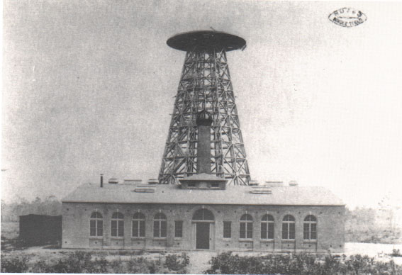
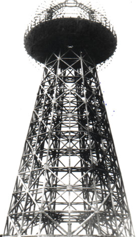
40°56′51″N 72°53′54″W / 40.94759700°N 72.89820700°W
- Small-scale demonstration of Tesla's system for the transmission of electrical energy without wires on YouTube.
- Tesla Wardenclyffe Science Center, Plaque [2]
- Designated Superfund Site
- Howstuffworks "How Wireless Power Works" — describes wireless power transmission using inductive and radiative techniques
- History of Microwave Power Transmission before 1980
- The SHARP's Stationary High Altitude Relay Platform, microwave beam powered
- MIT Prof. Marin Soljacic Wireless Power Transmission page
- Anticipating MIT Witricity — Nikola Tesla demonstrated the electrodynamic inductive effect over 110 years ago.
- Wireless Power Consortium - group of companies developing a standard for mid-range wireless power