{{multiple issues|
{{Refimprove|date=October 2011}}
{{Expert-subject |talk=Expert attention |date=August 2012}}
}}
_and_down_wind_(left).jpg)
Left-hand boat: Down wind with stalled airfow— predominant drag component propels the boat with little heeling moment.
Right-hand boat: Up wind (close-hauled) with attached airflow—predominant lift component both propels the boat and contributes to heel.
Forces on sails are primarily due to movement of air near and relative to the sails. By the law of conservation of momentum, the wind moves the sail as the sail redirects the air backwards .[1][2][3] Analyzing and modeling the forces on sails is important for the design and operation of the sails and whatever they are moving, sailboats, ice boats, sailboards, land sailing vehicles or windmill sail rotors. [4] [5][6] This analysis is important to boat design, operation, balance, stability, seakindliness and seaworthiness.[7]
Aerodynamic forces from air pressure differences causing normal stress perpendicular to the sail, and air viscosity causing shear stress parallel to the sail along the entire surface of the sails can be summed into one net force vector. Net aerodynamic force may be decomposed with respect to a boat's course over water into components acting in six degrees of freedom. [8] Two components with respect to wind direction can also be resolved: drag, which is the component directed down wind, and lift, which is the component normal to the wind and perpendicular to drag. [9]
The force analysis varies most significantly with orientation of the sail to apparent wind. [10] [11] [12] Briefly, when the sail is oriented at a right angle to the wind, as in a boat sailing downwind, the forward aerodynamic force component is almost entirely derived from the normal form drag component - the wind "pushes" the sail along in the direction of the wind. When the sail is arranged across or into the wind the sail acts as an airfoil. The resulting surface force includes a lift component normal to the wind on the sail predominantly from pressure, as well as a drag component parallel to wind predominantly from parasitic drag, that is, some combination of form drag, viscous drag and induced drag. The resulting forward driving component varies with point of sail and other factors.
Sailboat velocity, sail chord height and mast orientation may affect apparent wind velocity relative to the sail. Other factors to do with sail shape, size and trim, sea and air conditions, vessel orientation, heading, hydrostatic and hydrodynamic parameters also interact with each other and sail forces. [13]

Sailboat A is close hauled. Sailboat B is on a beam reach. Sailboat C is on a broad reach.
VT = True wind
VB = Boat velocity
VA = Apparent wind
FT = Total Aerodynamic Force on sail
FR = Driving force component
FLAT = Lateral component
Note that as the boat sails further from the wind, the apparent wind becomes smaller and the lateral component becomes less. Note also that the boat speed is highest on the beam reach.[14]
Overview edit
The analysis of the forces on sails takes into account the theoretical location of the propulsive force or centre of effort, the direction of the force, and the intensity and distribution of the aerodynamic surface force.
The fluid mechanics and aerodynamics airflow calculations for a boat are more complex than for a rigid winged aircraft. Structural analysis also is involved in modern optimal sail design and manufacture. Aeroelasticity models, combining computational fluid dynamics and structural analysis, are at the frontiers of sail study and design.[5] However, turbulence and detachment of the boundary layer are not yet fully understood.[15] Computational limitations persist.[16] The theoretical results are corrected by reality. So, wind tunnel scale model and full scale testing of sails are required for optimum sail design, function and trim.
Some complexities of boat sails:
- The wind is not constant.
- The boat is not traveling in uniform velocity.
- There may be a mast in front of the sail, disturbing the airflow, although this may be mitigated by profiling it.
- A mast is not infinitely stiff.
- The boat profile and position influence the airflow.
- A sail is usually made of thin and deformable fabric.
- The air is viscous, causing losses by friction.
- The flow of the air varies from slow to fast and turbulent to laminar.
Though some software algorithms attempt to model these complexities,[17][18][19] the following assumptions make the analysis much simpler:
- the water more or less flat
- the wind more or less constant
- the sail is set and is not adjusted
Factors affecting aerodynamic force edit
Pressure on the sail edit
For the purposes of modern sail making and study, pressure distribution measurements are done in wind tunnel and full scale experiments as well as in computer models.[4][20][21][22][23] [24]
According to kinetic theory, at the microscopic level, air pressure is the result of collisions between perpetually moving air particles. Their energy, measured by temperature, determines their velocity. In still air, the average particle of air randomly moves around an imaginary fixed point in space, colliding with other particles without too much average movement away from this point. Wind is the particles moving in large numbers in the same direction. So, air pressure on a sail has two origins: temperature and the mechanical influence of wind.
Pitot tubes[25] and other types of manometers are used in wind tunnel and full scale testing to measure the differences between local static pressures at various points on the sail and atmospheric pressure (static pressure in undisturbed flow). Results are graphed as pressure coefficients (static pressure difference over wind induced dynamic pressure) to obtain windward "pressure" to leeward "suction" distribution curves along the mast/sail's chord.[26][27][28][29][30]
Researchers modelling sails and masts using computer and experimental methods have found a complicated picture of airflow patterns around the sail and in the boundary layer.[31] Wilkinson, modelling the boundary layer in two dimensions, has described nine regions around the sail: 1. Upper mast attached airflow. 2. Upper separation bubble. 3. Upper reattachment region. 4. Upper aerofoil attached flow region. 5. Trailing edge separation region. 6. Lower mast attached flow region. 7. Lower separation bubble. 8. Lower reattachment region. 9. Lower aerofoil attached flow region.[32] This helpful 2d model is four dimensional reality simplified.
Role of wind edit

The wind velocity with respect to the sail, that is the wind's magnitude and direction, has a very major role on sail forces.
With the sail's chord oriented in exactly the wind's line there is minimal force generated. The sail luffs.
When the sail is perpendicular to the wind form drag from wind pressure propels the sail.
With the sail at a greater than zero to less than 90 degree inclination to wind, combinations of largely laminar air flow, viscous forces, and some turbulence combine to induce varied degrees of force on different parts of the sail. The picture shown adjacent models air flow and pressure patterns on a typical upwind sail.
Wind usually increases with chord altitude which in turn increases magnitude of force and alters its direction on the sail.
The rest of the article details wind's effects on sail forces.
Influence of apparent wind edit


When a sailed vessel or rotor is moving, its velocity creates a headwind, opposite in direction to the course traveled. The vector sum of the true wind velocity and the headwind velocity is called the apparent wind. If a boat moves upwind, the apparent wind magnitude is larger than the true wind's. The direction component of the wind vector may vary as well. Downwind, the effect is reversed, winds are subtracted and the apparent wind magnitude is lower than the true wind.
The apparent wind varies over boats sails depending on: the angle between course sailed and true wind direction, the boat speed, variations in true wind velocity at different altitudes above the sea, rolling and pitching of the boat. This influences boat sail design, twist and trim. [33] [34] [35]
For the scalar components of variables of the the illustration on the right, and
- : The apparent wind speed component opposite to course traveled.

- : The apparent wind speed component normal to mast and course direction.

- : True wind to course or pointing angle.
- : Apparent wind angle.
- : Heel angle.

This is the general apparent wind formula as a function of boat speed, true wind and heel angle:

Neglecting leeway.


Value of force edit
When the winds passes around a sail profile, it creates a pressure on the lower windward surface and a depression on the upper leeward surface. The integrated pressure difference on the surface of the sail provides aerodynamic force. (see Methods to determine lift on an airfoil).
The scalar value of total aerodynamic force acting on a sail is:


with
- : value of force obtained with maximum wind

- : Aerodynamic coefficient

According to the Bernoulli equation, the value of maximum force of wind over the entire surface of the sail is:

The actual value of force on sail is:

with
- : total aerodynamic force vector

- : total aerodynamic force value
- : maximum dynamic pressure or kinetic energy density of the air with respect to the sail; (see Max Q)

- (rho) : air density ( varies with the temperature and the pressure) ;

- : The sail area.

- : aerodynamic coefficient, which is dimensionless. It is the sum of the percentages of recovered energy on the leeward side and the windward side.[36] For this reason, the aerodynamic coefficient can be greater than 1, depending on the angle of upwind sailing.
- : speed of the wind relative to the sail (Apparent wind).

The sail is deformed by the wind, taking an airfoil form. When the flow of air around the profile is laminar the telltales of the sail (tufts of yarn or ribbon attached to it) are stable, and the wind induced depression factor becomes crucial. Based on studies and theories of sail design:[37]
- Depression on the upper (leeward side) represents two thirds of the aerodynamic force,
- The pressure on the lower surface (facing the wind) represents one third of the aerodynamic force.
Explanation Briefly, each parcel of air crashing onto a small surface element of the sail, , generates a force . The force, , exerted on that part of the sail equals the pressure of the air, , on the sail times the small surface area in a direction opposite to the normal unit vector, :
The airflow formula is derived from Bernoulli's principle which implies that at any given point near the sail, with increasing air speed there is decreasing pressure: In steady state, along a pathline, and if heat transfer is neglected, with , the speed of the wind relative to the sail; (rho), the air density; , the magnitude of acceleration of gravity; the elevation of a point on the pathline; and , the pressure at the point:
As the elevation changes are small and are negligible compared to other terms, then :
The fluid is considered as incompressible or has little density change. (At Mach = 0.4, the error remains below 2%). At constant speed, consider that the sail which moves in the air at speed or that the air reaches the speed on the sail are exactly equivalent. Suppose that the air is fixed and the sail moves. Applying the formula to the parcel of air over the sail and then the same parcel of air before its arrival on the sail:
- so
The pressure on the sail, , is the difference between total pressure(stagnation pressure), , and the dynamic pressure, . The total pressure is constant on the pathline. So overall it vanishes when integrating the formula over the entire surface of sail, as pressure from one side of the sail is exactly balanced by the total pressure on the other side of sail, and is therefore eliminated. This leaves the dynamic pressure remaining:
The dynamic pressure is equal to . The dynamic pressure is the volume density of the kinetic energy of the air parcel .
where .
In this formula is is unknown but bounded. Indeed is between 0 and because, if the speed exceeds , that means the surplus energy comes from another energy source which the Bernoulli principle has neglected, i.e. other sail generated aerodynamic phenomena (shock wave ...?).
Its maximum is Max Q
With a percentage of the kinetic energy density ranging from 0-100%. The percentage is unknown, it must be determined by other means (additional equation or testing).
Hence integrating over the whole surface :
with
- : value of force obtained with maximum wind ;
- : aerodynamic coefficient. The portion of dynamic pressure (or the energy density) transmitted to the sail.
Note that the total surface area, , is equal to the surface of the windward inner surface, , plus the leeward exterior surface, : .
with
But for practical reasons of comparisons of airfoils, the surface, , used in the tables is not the total surface of the object (wing, rudder or sail), but a characteristic surface. The virtual surface intersecting the chord, , is often used.
The form factors, and relate inner and outer to chord surfaces: , .[40]
So
- = coefficient of lift found in tables.
As the tables are based on the characteristic surface , it follows that the coefficient in the tables depends on two factors:
- a percentage factor of transmission of the dynamic pressure (or energy) and
- form factors. and .
In a slim sail airfoil profile, the surface intersecting the chord is close to the other surfaces, that is to say .
Usually, when it is said that sail is 10m ², it actually means that the surface of the upper surface of the airfoil wing is 10m ². The actual surface of the sail including both sides is 20m ², but it is the value of 10m ² which must be used in the formula for lift tables.
Although this calculation is an aid to understanding, the exact calculation of c is complex and uses the fundamental principles of dynamics. The calculation is discussed in the section: The case of multiple sails. In the following section, to lighten the notation, will be noted and will be noted .


Sail force components and relations edit
- Aerodynamic forces in balance with hydrodynamic forces on a close-hauled sailboat
-
 Top view. CE centre of effort. VB boat velocity, VA apparent wind, VT true wind, β apparent wind angle,αj angle of attack on jib, αm angle of attack on main (discounting sail interaction), λ leeway. FT total aerodynamic force including: FR forward force, FLAT side force, L lift, D drag. CLR centre of lateral resistance. FI total hydrodynamic force composed of: PI hydrodynamic lift, PLAT hydrodynamic lateral force, RI hydrodynamic resistance.
 -
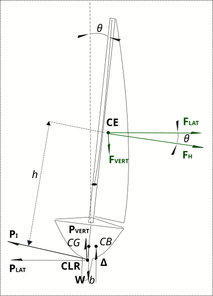 Stern view. θ heel angle. FH heel force, FVERT aerodynamic vertical force. PVERT hydrodynamic vertical force. CG centre of gravity. CB centre of buoyancy. W hydrostatic displacement weight. Δ buoyancy force. heeling moment (FH x h)=righting moment (Δxb).


Centre of effort edit
The point of origin of net aerodynamic force on sails is the centre of effort (or also centre of pressure). In a first approximate approach, the location of the centre of effort is the geometric centre of the sail. Filled with wind, the sail has a roughly spherical polygon shape and if the shape is stable, then the location of centre of effort is stable. The position of centre of effort will vary with sail plan, sail trim or airfoil profile, boat trim and point of sail.[41] [42] [43]
Net aerodynamic force edit
The net aerodynamic force on the sail is located quasi at the maximum draught intersecting the camber of the sail and passing through a plane intersecting the centre of effort, normal to the mast, quasi perpendicular to the chord of the sail (a straight line between the leading edge (luff) and the trailing edge (leech)).
Force components with respect to course edit
Net aerodynamic force may be decomposed into the three translation directions with respect to a boat's course in a seaway: surge (forward/astern); sway (starboard/port, relevant to leeway); heave (up/down). The force terms of torque in the three rotation directions, roll (rotation about surge axis, relevant to heeling). pitch (rotation about sway axis), yaw (rotation about heave axis, relevant to broaching) may be also derived. The scalar values and direction of these components may be very dynamic and dependent on many variables on a boat and in a seaway including the point of sail.[7]
The net force vector, , is resolved into components in relation to course in a seaway with:
- = the driving force directed along the course sailed

and
- = the heeling force perpendicular to the course and the mast.

The heeling force can be resolved as a function of heel angle, , to:

- , the lateral or leeway force

and
- , the vertical or heave force.

Force components with respect to wind edit
Moving viscous air on an airfoil disrupts the air flow around the airfoil. This disturbance causes considerable forces in line with the chord, perpendicular to it, and in the remaining dimension at the ends of the airfoil. The total force is calculated or measured in an air stream, with speed as uniform as possible, arriving on the sail at angle of attack, . The force is decomposed along three dimensions with respect to wind direction relative to the sail where the direction of particles' movement is not yet disrupted by the sail, the freestream.


The three dimensional vector relationship:[44][45][46]
- .

The values of the forces have the same general equation . The respective aerodynamic force and coefficient is adapted to each axis.

with:
- : The axis in line with the freestream. Force projected on this axis is called drag . By nature this force is resistive, i.e. the profile takes energy from the air. Here and in the literature the drag coefficient is noted .


- : The force in the direction of the span axis is called lateral lift. It is zero for an infinitely long airfoil. For a boat sail, the profile has two ends and thus the lateral air forces are balanced, and usually the side lift is negligible. The spinnaker, however, with its low aspect ratio and high camber draught generates significant forces along the three axes.

- : The axis perpendicular to the freestream, and perpendicular to the wingspan.[47] Force projected on this axis is lift . The direction of this force with respect to the sail varies with the value of the incidence. In the literature lift coefficient is also or here .


Relation between aerodynamic force components edit

Tables are used to calculate expected lift and drag components for various wind angles of attack, , on sails. The values of driving force and lateral force with apparent wind angle assuming no heel are related to lift and drag thus:


| Proof |
|---|
 |
To account for change in apparent wind with heeling, an adjusted effective apparent wind speed and effective apparent angle can be calculated:
For:
- : True wind speed

- : Effective apparent wind speed

- : True wind angle
- : Effective apparent wind angle

- : Heel angle
- : Apparent wind speed opposite to direction of motion
- : Apparent wind speed perpendicular to mast and direction of motion
- : Boat speed

This is the general apparent wind formula as a function of boat speed and true wind:
For convenience, this neglects leeway.


Observe that the higher the boat points into the wind, decreasing true wind angle, the greater the apparent wind component opposite to course, the less apparent side wind and the greater the total apparent wind, which increases the scope for aerodynamic force on the sail.
Because the apparent wind component at right angles to the boat's motion is proportionate to the cosine of heel angle and the component in line with boat direction is not affected, for a given true wind, the greater the heel angle the less the effective apparent wind and accordingly the less aerodynamic force possible. [34] [48]
While drag and lift components depend directly on angle of attack of airflow on sails, forward and heeling force on a boat depend indirectly on this and directly on apparent wind angle. The crew picks the best angle of incidence of sails, , while apparent wind angle, , follows based on dynamic equilibrium contributed by various aerodynamic and hydrodynamic factors while under sail. The diagram at right shows optimum total sail force, , as dictated by aero-hydrodynamic balance and sail trim angle, , superimposed upon the lift vs. drag polar curve for the sail. The total force vector originates at the centre of effort on the sail and finishes on the point on the curve corresponding to angle of attack, . Note that, according to course theorem, apparent wind angle equals the sum of the aero and hyrodynamic drag angles .


Wind and sail interactions edit
Comparing stalled with attached flow edit
To compare cases with and without lift.[49] take a gaff sail that is rectangular and approximately vertical, with an area of 10 m² - 2.5 m of foot by 4 m of leech. The apparent wind is 8.3 m/s (about 30 km/h). The boat is presumed to have uniform velocity, no heel and no pitch and there are no waves. The density of air is set at: ρ = 1.2 kg/m³.
Sailing in stalled flow edit
The boat is running downwind. The shape of the sail is approximated by a plane perpendicular to the apparent wind. The depression effect on the sail is second order, and therefore negligible. The remaining pressures are:
- on the windward side atmospheric pressure and wind pressure
- on the leeward side only the atmospheric pressure
Forces of atmospheric pressure cancel out. There remains only pressure generated by the wind.
Roughly speaking, collisions of particles on the sail forward all their energy from wind to 90% of the surface of the sail. This means that the CD or aerodynamic (drag) coefficient is equal to 0.9.

Wind on sail could be modelled as a jet of air with the sail a deflector. In this case the theorem of momentum is applied. Effort on sail varies as a sinusoid of angle of attack, , with wind.[50][51][52][53] Force is

At 90° and running downwind, force is maximal and then , so .


In reality, depends on the profile. The coefficient is set between around 1 to 2.[56] Two is also a good number for many rigid profiles [57] and around one is a good number for a sail.[58]

Sailing in attached flow edit
For a boat close hauled, with the sail set at, for example, 15° relative to the apparent wind, the effect of depression on the leeward side comes into play. As air pressure forces cancel out, significant effects resulting in aerodynamic force are:
- on the windward side wind pressure
- on the leeward side wind depression
The only unknown to be determined is the drag coefficient. In a well trimmed sail the curve profile is close to optimal airfoil shape NACA 0012.[59][60] A less well trimmed sail, perhaps of older technology, will have greater draft with more camber. The aerodynamic lift coefficient will be higher but the sail will be less efficient with a lower lift/drag ratio (L/D). The sail profile may be similar to NACA 0015, NACA 0018.[61]
For a given profile, there are tables which give the total aerodynamic force coefficient (C), which depends on several variables:
- Incidence angle of apparent wind to sail profile,
- The slope of lift vs drag of the sail, which depends on its Aspect ratio (see Eiffel's polar curve diagrams for varying aspect ratios),
- The surface roughness and Reynolds number, which affect the flow of fluid (laminar, turbulent).
The coefficient is determined for a stable and uniform fluid, and a profile of infinite extension.
The Reynolds number is the ratio of inertial forces to viscous forces:

with
- - fluid speed or apparent wind [m/s]
- - characteristic chord length - since this is a rectangular sail the length at any height will do, e.g. the foot of the sail [m]
- - fluid kinematic viscosity: [m2/s]
- - air density [kg/m³]
- or alternately - air dynamic viscosity [Pa] or Poiseuille [pl]


so for this sail about

With an incidence angle of 15° and a Reynolds number of one million a NACA0012 profile reached a C of 1.5 (as opposed to C of 0.9 for 90° incidence).

The lift has increased by 50%. The force on the sheets and rig also increases by 50% for the same apparent wind.
Contribution of lift to the progress of the vessel edit
When running downwind the direction of the apparent wind is equal to that of the true wind and most of the sail force contributes to the advancement of the ship. There is no sail lift, so the boat can not go faster than the wind, and propulsive force decreases gradually. When the ship approaches the speed of the true wind, the apparent wind speed and the force drop to zero.
- Polar diagrams, showing lift (L), drag (D), total aerodynamic force (FT), forward driving force (FR), and lateral force (FLAT) for different points of sail
(VA is constant in these examples, which means that either VT or VB varies.)
-
 Close-hauled: Note that the lateral force is highest and driving force is lowest close to the wind.
 -
 Reach: Note slight change in angle of attack (alpha), increase in driving force and decrease in lateral force.
 -
 Broad Reach: Note that with apparent wind behind the sail, the sail has stalled and lift has diminished.


In the cases with lift, the sail has an angle of incidence with the apparent wind. The apparent wind also forms an angle with the true wind. Similarly, wind creates an angle to the direction taken by the ship. Forces on the sail do not contribute fully to the advancement of ship. With a ship pointing close hauled, an example scenario is:
- , angle between apparent wind and ship's course, is 40°.
- , incidence angle between apparent wind and sail chord, is 20°.
- , leeway, is nil.

The lift force vector, perpendicular to the apparent wind, does not participate fully in the progress of the vessel. It forms an angle of 40° to the course sailed. The propulsive force vector is more than 76% of the total value. The remaining 36%[63] is perpendicular to the vessel, and generates leeway angle and heeling moment.
For the same sail with the same apparent wind speed, lift coefficient is 1.5 close hauled and 1 downwind. The vector of force towards advancement of the vessel remains 15% above cases without lift.
The faster the boat travels the more the apparent wind increases. So the force on the sail increases. At each speed increase apparent wind direction moves. So, re-trimming the sail is needed for optimum effect (maximum lift). Also, the faster the boat travels, the smaller the angle of the apparent wind to the direction of the ship. So sail force angle is less oriented towards the course of the boat, requiring bearing down a bit to gain maximum power sailing conditions. The ship can go faster than the true wind. The ship to wind angle can be quite small. Consequently the point of sail may approach the dead zone requiring the boat to back away from the wind.
Relationship of aerodynamic coefficients to angle of incidence: polar diagram edit

The aerodynamic coefficients of the sail vary with angle of attack (incidence of chord to apparent wind). The analysis on a polar diagram correlates to the respective lift and drag components of aerodynamic force:
- The component perpendicular to the apparent wind is called the lift coefficient;
- The component parallel to the apparent wind is called the drag coefficient.
Each incidence angle corresponds with a single lift-drag pair.
Summarising the behaviour of the sail at varying incidence:[64]
- When the sail is loose, this is the equivalent to having no sail. Lift and drag from the sail are effectively null.[65]
- When the sail is perpendicular to the wind, the air movement is turbulent.[66] This is the case of no lift and maximum drag.
- These are the intermediate cases:
- Sail loose to maximum lift: the flow is attached, i.e. there is an airfoil. There are no eddies (dead zones) created on the sail. It is noted in the case of a good well trimmed sail, maximum lift is greater than maximum drag.
- Maximum lift to maximum dead zone: the wind does not stick properly to profile of the sail. Flow is less stable. Air becomes gradually lifted or taken off. This creates an area on leeward side, a dead zone where depressions form on the sail. At typical angle, dead zone has invaded the leeward side.
- The dead zone to maximum drag: Dead zone has invaded the whole face on the leeward side, only on the windward side is there an effect. Air in these high angles, is somewhat deviated from its trajectory. Air particles are just crashing on all surfaces of windward side. Force is almost constant, so the polar sailing describes an arc of a circle.
As the lift is more effective than drag in contributing to the advancement of ship, sail makers trying to increase the zone of lift, i.e. increase force of lift and angle of incidence. The task of a knowledgeable sailmaker is to decrease the size of the dead zone at high angles of incidence, i.e. to control the boundary layer.[67]
Optimum angle of incidence for heading and wind edit
Angle of attack is the most significant practical factor in optimising sail driving force and velocity made good in attached flow conditions (reaching or close hauled). The choice of this angle by the boat helmsman is influenced by point of sail, boat aero/hydrodynamic balance, and wind strength.
For a wind abeam reaching scenario, in a properly trimmed and twisted sail the best driving force has been found to be achieved by adjusting angle of incidence to maximum aerodynamic coefficient on the polar curve.
However, for closed hauled sailing in strong winds, is is optimal to minimise the ratio of heeling force to driving force. Though for close hauled sailing in lighter winds heeling force restriction is negligible.
Course into the apparent wind is always limited by the aero-hydrodynamic balance of the particular vessel as expressed by course theorem or Lanchester's Principle :
- : apparent course angle
- : aerodynamic drag angle

- : hydrodynamic drag angle

For more detailed discussion on optimising performance see the efficiency (L/D) and power section.
Influence of rigging tension on lift performance edit
Trimming a sail involves two parameters:
- Angle of attack, or incidence. i.e. the angle of apparent wind to sail chord to create maximum lift, or a maximum sail efficiency L/D. This angle varies with sail height, which is aerodynamic twist.
- Airfoil profile which is composed of: 1. Camber of the sail as defined as the ratio of maximum draft depth to chord length and 2. Draft position.
Sail set and shape is generally flexible.[70] When the sail is operating in lift, if a sail is not properly inflated and stretched, there are wrinkles on the sail. These folds form a break in the profile. The air does not slip along the sail. The air streams come off the airfoil profile. Areas of recirculation or turbulent separation bubbles appear. These areas considerably diminish the performance of the sail. The assumption of a non wrinkled profile will simplify sail analysis.
A sail may be rigid where the canopy is composed of non stretchy fiber. Tightening a flat piece of such cloth inflated by the wind results in folds at the attachment points. To avoid wrinkles, the sail could be tightened harder. The tension can be considerable to eliminate all wrinkles. So, in the case of a taut rigid sail, the inflated shape is static, hollow and with its draft position immobile.
The more elastic sail deforms slightly to its locations of high stress on the material, thereby eliminating wrinkles. The sail is no longer flat. Consequently, the sail can take several forms. By varying the tension of the sail, it is more or less empty. It is possible to vary the shape of the sail without folds. The potential sail shapes are intrinsically linked to the cut of the sail. So in the elastic case, there is a family of possible forms and draft depths and positions the sail may take.
Sailmakers try to build rigidity into sails for a predictable working shape with a degree of advantageous resilience depending on the sail's type, application and range: racing, cruising, high, moderate or variable wind, etc.
The airfoil profile of the sail changes depending on the sail trim. At a given incidence, the sail can take different forms. The shape depends on the rigging tensions such as on clew corner of the sail, the tack with Cunningham adjustment, the backstay, the outhaul, the halyards or the boom vang (kicking strap). These elements help determine the shape of the sail. More exactly, they can decide position of maximum draft along the camber of the sail.[71]
Each profile represents an appropriate value of CL (lift coefficient). The position of the draft along the chord with the most lift is about 40% of the foot from luff. The leeward side of a sail is close to the NACA series 0012 (NACA 0015, NACA 0018, etc.) within the possibilities of trimming.
The position of the draft is not independent of the camber setting. These parameters are linked by the shape of sail. Modifying the camber modifies the position of the draft.
Camber edit
The curves of propulsive component of lift and heel versus the angle of attack vary with the camber of the sail, that is to say, the biggest draft depth relative to the chord of the sail. A sail with high camber has a higher aerodynamic coefficient and, potentially, a greater propulsive force. Though the heeling coefficient varies with draft depth in the same direction. So finding the optimal camber will be a compromise between achieving a large propulsive force and an acceptable list.[72] · [73]

Note that with a small camber (1 / 20), performance degrades significantly. The propulsion coefficient plateaus around a ceiling of 1.0.
Draft position edit
The curves of propulsive lift and heel as a function of the angle of attack also depend on the position of the draft's proximity to the luff.[74] · .[75]

Influence of Aspect ratio and Sail Planform on Induced Drag edit
Sails are not infinitely long. They have ends. For the mainsail:
The transfer of air molecules from the windward pressured side to the leeward depressed side around the edge the thin sail is very violent. This creates significant turbulence, loss of pressure difference and loss of propulsion. On the end of a wing this is manifest as wingtip vortex. On a Bermuda sail, foot and leech are two areas where this phenomenon exists. The drag of leech is included in drag in the usual lift curves. The sail airfoil profile is considered as infinite (i.e. no ends). But foot drag is calculated separately. This loss of efficiency of the sail at the foot is called Lift-induced drag.
Influence on coefficients edit

Lift-induced drag is directly related to the narrowness of the extremities due to premature stall over the heavily loaded short chord profile. The longer is the narrow head, the higher is induced drag. Conversely, the sail can be reefed, i.e. reduce surface of the sail without reducing the length of the head. This means that value of the lift-induced drag will be substantially the same. For a given length of head, the more sail area, the lower is the ratio of lift-induced drag on lift. The more elongated the sail, the less lift-induced drag alters value of the lift coefficient.

Lift-induced drag on the sail also depends on aspect ratio, Λ. Aspect ratio is defined:[76]

with
- the length of luff
- the surface area of the sail.

The lift-induced drag coefficient is:

with
- : Lift coefficient of airfoil
- :
- (often in the literature): Aspect ratio (wing) (dimensionless)
- : Oswald efficiency number (less than 1) which depends on the distribution of lift over the sail span. "e" could be equal to 1 for an "ideal" distribution of lift (elliptical). Elliptically shaped ends help reduce induced drag. In practice "e" is the order of 0.75 to 0.85. Only a three-dimensional model and tests can determine the value of "e".


Optimal distribution for maximum reduction of lift-induced drag is elliptical in shape.[77][78] Accordingly, the luff will be elliptical. So, the mast is not straight as on a classic boat, rather designed with the closest possible form to an ellipse. An elliptically configured mast is possible with modern materials. This is very pronounced on sailboards. On modern sailboats the mast is curved thanks to shrouds and backstays. Similarly, the leech will be elliptical.[79] This profile is not natural for a flexible sail. So, mainsails have battens to maintain this roach curve.
An ideal lift-induced drag distribution creates an elliptical sail. But current sails are rather a half-ellipse, as if the second half part of the ellipse was completely immersed in the sea. This is logical because, as wind speed is nil at the sea level (0 m), the sea is equivalent to a mirror from an aerodynamic point of view.[80] So only half an ellipse in air is necessary.
Influence on forces edit
Formulae are :
- Lift,
- .
- Induced drag force,
- .
- Induced drag coefficient,
- .
- Aspect ratio,
- .


Then :
- .

This result is important (see Efficiency and Power section). The induced drag force (not coefficient) is independent of aspect ratio, . In sailing, lift is quite often limited by the maximum righting moment. Induced drag force doesn't depend on , but does depend on the lift coefficient, , which depends on sail area. So, for optimal performance, may be changed while keeping span the same. This concept is often used by airplane designers.
Influence of the height of the foot relative to sea level edit
The gap between the edge of the sail and the sea surface has a significant influence on performance of a Bermudan type sail. In effect it creates an additional trailing edge vortex. The vortex would be nonexistent if the border were in contact with the sea. This vortex consumes extra energy and thus modifies the coefficients of lift and drag. The hole is not completely empty, as the sail is partially filled by the freeboard and superstructure of any sailboat.
For a height between the edge of the sail and the deck of the sailboat of 6% of the length of the mast, changes are:
- a 20% increase in the drag coefficient
- a 10% loss in the lift coefficient.[82]
The crab claw sail may partially circumvent this problem by harnessing the delta-wing's vortex lift.
Shape of luff, leech, and foot edit
A sail hauled up has a three-dimensional shape. This form is chosen by the sailmaker. The 3D shape is different for the hauled up form compared to when empty of wind. This must be taken into account when cutting the sail.
The general shape of a sail is a deformed polygon. The polygon is slightly distorted in the case of a Bermuda sail and heavily distorted in the case of a spinnaker. The shape of edges empty is different from shape of edges once the sail is hauled up. Convex empty can go to straight edge when the sail is hauled up.
Edges can be:
- convex
- concave
- straight
When the convex shape is not natural (except for a free edge in a spinnaker), the sail is equipped with battens to maintain this pronounced convex shape. Except for the spinnaker with a balloon shape, the variation of edge empty compared to straight line remains low, a few centimeters.
Once hauled up, an elliptical sail would be ideal. But as the sail is not rigid:
- You need a mast, which for reasons of technical feasibility, needs to be quite straight.
- Flexibility of the sail can bring other problems, which are better to fix at the expense of an ideal convex elliptic shape.
Leech edit
On a Bermudan type sail the oval is the ideal (convex), but a concave shaped leech improves the twist at the top of the sail and prevents overpowering the top of the sail in the gusts, thereby improving the boat's stability. The concave leech makes sailing more tolerant and more neutral. A convex shape is an easy way to increase the sail area (roach). Marchaj[83] discusses crescent shaped foils like a raked wing tip device as seen on various fish fins, Brazilian jungada sails, crab claw sails, and America's cup boat Stars and Stripes to reduce lift induced drag.
Luff edit
Once hauled up, the edge must be parallel to the forestay or mast. Masts and spars are very often, except in windsurfing, jangada boats, and proas, straight. So, a straight luff is usually needed.
But the draft of the sail is normally closer to luff than foot. So to facilitate the implementation of draft of the sail when hauled up, the empty form of luff is convex.[84] This convexity is called the luff curve. Sometimes rigging is complex and the mast is not straight.[85] In this case, the shape of luff empty can be convex at bottom and concave at the top.
Foot edit
Foot form has little importance, particularly on sails with a loose foot or free edge. Its shape is more motivated by aesthetic reasons. Often it is convex empty to be straight once hauled up. When the border is attached to a spar or boom a convex shape is preferred to facilitate formation of draft of the sail. On retractable booms, the shape of the edge of the border is chosen based on technical constraints associated with the reel than consideration of aerodynamics. A winglet[86] as used on airplanes to minimise lift induced drag is so far not practically seen on sails.
Influence of altitude: aerodynamic twist and sail twist edit

Earth planetary boundary layer effects cause a wind gradient. The rapid increase of the wind speed with altitude will increase both apparent wind speed, , and its angle of incidence to course sailed, . [87][88] When using sails with lift, the sail must be twisted to have a consistent angle of incidence of sail with apparent wind, , along the leading edge (luff). This results in the lower sail chords being at smaller sheeting angles to the course sailed, , than the upper chords to compensate for the smaller angle closer to the deck.

The air moves primarily in slices parallel to the ground or sea. While air density can be regarded as constant for our calculations of force, this is not the case for wind speed distribution. Wind speed will increase with altitude. At the sea surface, the difference of speed between air particles and water is zero. The wind speed increases strongly in the first ten meters.[89][90][91][92] KW Ruggles gives a generally accepted empirical formula for the relation of the wind speed with altitude:

With data collected by Rod Carr[96] the parameters are:
- a constant = 0.42,
- altitude in meters;
- "roughness length" is an altitude that reflects the state of the sea, i.e. the wave height and speed:
- 0.01 for 0-1 Beaufort;
- 0.5 2-3 Beaufort
- 5.0 to 4 Beaufort;
- 20 5-6 Beaufort;
- "friction velocity" = 0335 related to viscosity of air;
- general wind speed m / s.


In practice, the twist must be adjusted to optimize the performance of the sail. The primary means of control is the boom for a Bermuda mainsail. The more the boom is pulled down, the less twist. For the foresail, depending on the rig, twist is controlled by adjusting jib leech tension through sheet tension adjustments of: sheet angle with sheet block track (fair lead) position, jib halyard tension, jib Cunningham tension, or forestay tension.[97][98]
Influence of the roughness of the sail edit
As on a hull or wing, roughness plays a role on the performance of the sail. Small humps and hollows may have a stabilizing effect or facilitate stalls as when switching from laminar to turbulent flow. They also influence friction losses.
This area is the subject of research in real and wind tunnel conditions. It is currently not simulated numerically. It appears that at high Reynolds number, well chosen roughness prolongs the laminar mode incidence a few degrees more.[99][100]
Influence of the Reynolds number edit
The Reynolds number is a measure of the ratio of inertial forces to viscous forces in moving fluids. It also indicates degrees of laminar or turbulent flow. Laminar flow occurs at low Reynolds numbers, where viscous forces are dominant, and is characterised by smooth, constant fluid motion. Turbulent flow occurs at high Reynolds numbers and is dominated by inertial forces. Reynolds numbers are used in scale model testing to achieve dynamic similarity.
The stronger the wind, the more the air particles tend to continue moving in a straight line, so are less likely to stick to the wing, making the transition to turbulent mode nearer. The higher the Reynolds number the better the performance of the sail (within other optimal parameters.)[101]
In the general aerodynamic force formula , the aerodynamic coefficient, , depends on fluid speed, , and surface characteristics. The lift coefficient depends on Reynolds number as shown in the tables and polar diagrams. The Reynolds number is defined . The Reynolds number depends on wind speed, , and length, , travelled by the air (characteristic chord length) and kinematic viscosity, . But the influence of the Reynolds number is second order relative to other factors. The performance of the sail changes very little for a variation of the Reynolds number. The influence of very low Reynolds number is included within the tables (or chart) by plotting the lift coefficient (or drag) for several values of the Reynolds number (usually three values).


Increasing the incidence or the maximum lift coefficient by good choice of the Reynolds number is very interesting but secondary. The Reynolds number depends only on three parameters: speed, viscosity and length:
Viscosity is a physical constant, it is not an input variable for optimisation.
Wind speed is a variable of optimisation. It is obvious that we look for the highest possible wind speed on the sail for sailing maximum force much more than for reasons of Reynolds number. This parameter has already been optimised.
The sail is inherently inelastic and of fixed size. So, the characteristic length is fixed for a given sail. Chord length optimisation is the responsibility of the naval architect, except for sail changes by the sailor. Performance tuning of the sails by varying the characteristic length of the Reynolds number is masked by the optimisation of other parameters, such as looking for better sailing performance by adjusting the weight of the sails. The weight of the sail is an important point for the balance of the ship. Just a little more weight in the higher part of the sail may create a major change affecting the balance of the ship. Or, for high winds, the sail fabric must resist tearing, so be heavy. The sailor is looking for a set of sails adapted to each range of wind speeds for reasons of weight more than for reasons of Reynolds number: jib, storm sail, main sail, spinnaker, light genoa, heavy genoa, etc. Each wind speed has its sail. Higher winds tend to force small characteristic lengths. The choice of the shape of the sails and therefore the characteristic length is guided by other criteria more important than the Reynolds number. The price of a sail is very high and therefore, limits the number of sails.
The coefficients of lift and drag, including the influence of the Reynolds number, are calculated by solving the equations of physics governing the flow of air over a wing using computed simulation models. The results found are well correlated with reality, less than 3% error.[102]
Efficiency and Power edit

Polar curves of lift versus drag initially have a high slope. This is very well explained by the theory of thin profiles. The initial constant drag and lift slope becomes more horizontal, as maximum lift is approached. Then at higher angles of incidence a dead zone appears, reducing the effectiveness of the sail. The goal of the sailor is to set the sail in the incidence angle where the pressure is maximum. Considering the proper tuning for a Bermuda-rigged boat, it is rare to set a sail with theoretical optimum L/D, efficiency. The apparent wind is not constant for two reasons: wind and sea. The wind itself is not constant, or even simply variant. There are swings in the wind, there are gusts of wind and wind shifts. Even assuming constant wind, the boat can be raised with the swell or wave, the top of the sail finding faster winds, or in the troughs there is less wind. Up or down a wave the boat pitches, that is to say, the top of the sail is propelled forward and back constantly changing the apparent wind speed, relative to the sail. The apparent wind changes all the time and very quickly. It is often impossible to adapt to sea conditions with correspondingly fast adjustments of the sails. Therefore, it is impossible to be at the theoretical optimum. This is not necessarily a disadvantage as the "pumping" phenomenon of abrupt changes in incidence has been shown to increase lift beyond the steady flow situation.[103] Nevertheless, setting to the maximum optimum may prove quickly disastrous for a small change in wind. It is best to find an optimum setting more tolerant to changing conditions of apparent wind, state of equipment and weather.
The important parameter influencing the type of sail trim is the shape of the hull. The hull shape is elongated to provide a minimum of resistance to progress. We need to consider effects of wind on direction of the hull tilt: forward (pitch) or heel (roll). Downwind, sailing thrust is oriented in the direction of travel so will result in a forward pitch. Maximizing sail area may be important as the heeling force is minimal. The situation changes if part of the force is perpendicular to the vessel. For the same force as sailing downwind, the force perpendicular to the vessel may result in a substantial heel. Under heavy list, the top of the sail does not take advantage of stronger winds at altitude, where the wind can give maximum energy to sail and boat.[91][104][105][106][107]
The heel phenomenon is much more sensitive than sail induced pitching. Accordingly, to minimize the list, the type of setting will be different close to the wind versus downwind: Close hauled, the setting is for efficiency. When sailing downwind, the setting is for power.
Performance limitations of a sail edit
A sail can recover energy of the wind.[108] Once the particles have passed their energy to the sail, they must give way to new particles that will in turn give energy to the sail. As the old particles transmitting energy to the sail evacuate, these particles have retained a certain energy in order to escape. The remaining energy of the particle is not negligible. If the old particles evacuate too soon to make way for new particles, these particles carry with them a lot of energy. They then hand the sail less energy. So there is little energy per unit time, or power, transmitted to the sail. Conversely, if the old particles evacuate too slowly they certainly convey a lot of energy to sail but they prevent the new transmission of power. So there is little power transmitted to the sail. There is a balance between incoming particle speed and exit velocity, giving maximum power to the sail. This limit is called the Betz limit :


with

with
- : fluid density (1.23 kg / m³ in air at 20 °C)
- S: surface wind "cut" by the sail m²
- : speed incident (upstream) of the fluid in m / s, ie the apparent wind speed.
So the sail can not recover more than 60% of the energy in the wind. The rest being used to evacuate the air parcels off the surface of the sail. Note that the surface of the Betz limit is not the surface of the sail but the surface wind "cut" through the sail.[109]
The formula for the force on the sail is

where
is a characteristic surface in the case of sail on the surface of the chord.
is the aerodynamic coefficient.
represents the percentage of energy recovered over the upper(outer) surface multiplied by the upper(outer) surface area plus the percentage of energy recovered from the lower surface multiplied by the surface area of the lower(inner) surface. For a typically thin sail the upper surface area is identical to the lower surface area. The camber of the sail can be very important in lift mode lest the airflow comes off the airfoil and thus decreases the performance of the sail. Even for a highly deformed spinnaker, the spinnaker must be set to catch maximum wind. The upper surface area or the lower surface area are approximately equal to the surface area through the chord. The surface area of the sail is approximated to the surface area through the chord . So the drag coefficient has upper limit 2.

On the other hand, the apparent wind is related to the true wind and boat speed from the law of cosines formula:


with , the angle between true wind and the direction of movement of the boat in radian.
The apparent wind depends on the true wind and boat speed. The true wind speed is independent of the boat. The boat can take any apparent wind speed. So if the sailor increases the apparent wind with the true wind fixed, the boat speed increases, with some practical limits.
Research is intended to improve the speed of boats. But improvements are limited by the laws of physics. With all the advanced technology available, the aerodynamic coefficient has a theoretical limit, which limits the recoverable force at constant speed. Recovered energy from the wind intercepted by the sail is limited to 60%. The only way for the sailor to go faster is to increase the energy recovered per unit time (or power ) by increasing the surface wind intercepted by the canopy. Without going into calculations, the faster the boat moves, the more the surface area intercepted increases, the vessel has more energy per unit of time, it goes even faster. If the boat is faster, it enters a virtuous cycle. The area intercepted is even greater. It gets even more energy. It goes even faster than before. If the apparent wind increased indefinitely with no heeling problem and hull resistance, the boat would accelerate indefinitely. But, increasing the sail surface area, is limited by the strength of materials.
Efficiency (Lift/drag). Upwind sail cut and trim edit
| Low forward resistance and high lateral resistance optimises upwind sailing: |
|---|


In the example of upwind sailing, the apparent wind, with incidence, α, to the sail chord, is at an angle, β, to the course sailed. This means that:
- a (small) part of the drag slows the boat.
- the other part of the drag of the sail is involved in the vessel's heel and leeway, λ.
- much of the lift of the sail contributes to the advancement of the vessel,
- the other part of the lift of the sail is involved in the vessel's heel and leeway.[110]
Sailing high to the wind generates a perpendicular heeling force. Naval architects plan optimum heel to give maximum forward drive. Technical means used to counter the list include ballast, hydrofoils and counter ballasted keels. Heel can be almost completely offset by the counter- heel technology such as boom / swing keel, type of hydrofoil, etc. These technologies are costly in money, weight, complexity and speed of change of control, so they are reserved for elite competition. In normal cases, the heel remains as extra ballast begins to decrease forward drive. The architect must find a compromise between the amount of resources used to reduce the heel and the heel remaining reasonable. The naval architect often sets the optimal heel between 10° and 20° for monohulls.[111] As a result, the sailor must stick as much as possible to the best heel chosen by the architect. Less heel may mean that the boat is not allowing maximum sail performance. More heel means that the head of the sail drops, thus reducing pressure, in which case the sailing profile is not the best.
The sailor desires optimum heel, a heel giving optimum perpendicular force for the best resulting driving force and to minimise the ratio of perpendicular force to driving force.
This ratio depends on the point of sail, incidence, the drag and lift for a given profile.
As the lift is the main contributor to the force that drives the boat, and drag usually the main contributor to perpendicular heeling and leeway forces, it is desirable to maximise the L/D.
The point of sail, true wind to course angle, depends on the course chosen by the sailor. Each apparent wind angle relative to the course has a different optimum setting.
The sail trimmer will first select the trim profile giving maximum lift. Each profile corresponds to a different polar diagram. A sail is generally flexible, the sailor changes the trim through:[112]
- the position of the draft of the sail by adjusting the elements acting on the tension of the fabric of the sail
- adjusting twist of the sail using the leech tension lines such as boom vang or jib sheet angle adjustment.
Many polar curves exist for the possible sail twists and draft positions. The goal is choosing the optimal one.
The twist will be set for constant incidence angle along the luff for maximum sail performance, remembering that apparent wind strength and angle varies with altitude.
The best L/D is usually obtained when the draft is as far forward as possible. The more forward the draft, the greater the angle of incidence over the luff area. There comes an attack angle when the air streams do not stick to the sail, creating a dead zone of turbulence which reduces the efficiency of the sail. This inefficient zone is located just after the luff on the windward side. The tell tales in this area become unstable.[113] The flatter the stretched fabric over the sail is, the less the draft. The yacht has several elements acting on the tension of the fabric of the sail:
- Cunningham tension,
- the tack,
- the head point,
- the clew of the sail.
- the backstay,
- shrouds. They act indirectly.
These elements can interact. For example, backstay tension also affects the tension of the head point and therefore the shape of the luff. Both high clew sheet tension tightening the foot and a tighter backstay cause slackening of the leech.
For a flexible sail, the camber of the sail and position of the draft are linked. This is a result of their dependence on shape of the cut of the sail. The camber is a major factor for maximising lift. It is the naval architect or sail maker that sets the cut of the sail for the draft-camber relationship. The thickness of the airfoil profile corresponds to the thickness of sail fabric. Variations in thickness of a sail are negligible compared to the dimensions of the sail. Sail thickness is not a variable to optimise. Contrast mast thickness and profile which are much more important.[114]
For the naval architect the sail-shape offering a large L/D is one with a large aspect ratio. (see previous polar diagram) This explains why modern boats use the Bermudan rig.
Sail drag has three influences:
- induced drag (see influence of aspect ratio on the lift). As the profile is not of infinite length, the ends of the sail, foot and head, equalise the depression of the leeward surface with the pressure of the upwind surface. This dissipated pressure balance becomes the induced drag.
- friction drag, related to boundary layer laminar turbulent flow and roughness of fabric
- form drag, related to choice of the airfoil profile, camber, draft position, and mast profile
- ( interference drag is related to parts extraneous to the sail, but may influence rigging, boat and sail design)
Prandtl's lift theory applied to thin profile is less complex than the resolution of Navier-Stokes equations, but clearly explains the aspect ratio's effect on induced drag. It shows that the principal factor influencing L/D is induced drag. This theory is very close to reality for a low-impact thin profile.[115] Smaller secondary terms include the form drag and friction drag. This theory shows that the factor with main influence is aspect ratio.[116] The architect chooses the best aspect ratio for best sailing, confirming the choice of Bermudan rig. The sailor's choice of sail trim affects the factors of secondary importance.
Explanation Thin profile theory[117] is applied to a 3D profile. A conventional infinitely extended 2D profile of the thin profile theory is truncated. At each end section of the truncated profile there is a vortex that swirls over its whole periphery. The theory then gives the drag:[118]
with
- : Lift coefficient of profile
- : the circle circumference to diameter ratio, pi or 3.1416
- : Aspect ratio (dimensionless) with b the length of the luff and S the surface area of the sail.
- : Oswald efficiency number
The theory only models the induced drag. The form and friction drag are neglected.[119] To set the order of magnitude:
- ranges from about 0 to 1.5, a value of 1 is taken
- is between 0 and 1 for a sail is at about 0.8
For an Edel 2 sloop, the mainsail is 10 m2 with a foot of 2.5 m is = 1.6 for an Edel 2 is 0.2.But the sail's reflection in the sea must be taken into account. Neglecting the distance between the sea and the foot, the sail's surface area and length doubles. So is 0.1.
In reality, lies between these two values. This value varies depending on the state of the sea, that is depending on the quality of the mirror.
The calculation of the Oswald efficiency number is based on integral calculus. It is not addressed in the literature because it is calculated indirectly. The formulas are not all written with the Oswald efficiency number. There is also another notation :
Thin profile theory applied in 3D gives the formulas for the induced drag.[120] Note the case of a large cambered sail such as a genoa. The recalculation based on this camber is no longer negligible. Also note that can be calculated not using a Fourier series, but via the calculus.[121]
The lift/drag ratio is directly derived from the formula of the induced drag:
The theory then gives for the lift:[122][123]
with
- : Aspect ratio (dimensionless) with b is the length of the luff, S the surface area of the sail.
- : lift coefficient calculated by the theory with an infinite extension profile.
It should be noted that in the case of a sail wind speeds are far removed from Mach, it follows that the correction factor of the Mach number is approximated to 1.
The theory then gives for the infinite extension lift profile:
with α incident angle between the chord of the sail and the apparent wind. α0 3D coefficient is actually slightly different from the 2D calculation.
hence
The naval architect fixes and , while the sailor sets and . The sailor does not have a choice of total factor α0, i.e. She can not choose the full form of the profile. The set of possible profiles is limited. Indeed, the sail maker sets a cut of the sail therefore defines a set of profiles that can be made possible depending on sail trim. To illustrate, the sail may be cut to give a profile NACA0009 but if the sail is not taut it can become NACA0012 NACA0015 NACA0018 or in between, though the general shape remains the same. The relationship between draft position and camber, camber / chord, etc. are fixed. The choice of the general form is the responsibility of the sail maker or naval architect.
A high L/D is in the range of possible profiles of the sail set to a maximum draft, forward on the sail, with the sail taut.[124] Trimming to advance the draft position is desirable. But that does not mean it can be placed anywhere. The choice of the profile by the sail maker could for example result in maximum draft positioned at 30% or 50% of chord. In the first case flexibility of draft position will be between 30% and 100%, while in the second case between 50% and 100%.
Form drag and friction drag, have a secondary but significant impact for competition sailing.[125] The surface perpendicular to the wind is a factor, the greater the depth of the draft (camber) the smaller the L/D due to increased drag. Similarly increasing twist increases drag.[126] A flatter sail is preferable to a balloon shape. This implies that the general shape of a sail is set properly by a tense sail. But the sail should not be too tight as too much flatness decreases the lift.[127]
These calculations are approximations of reality. They are still relatively simple. They avoid the very heavy 3D calculations (see Forces on sails# Several sails : multi-dimensional problem resolution). They are handy for sizing a rig or to model its behaviour in full sail.


A higher L/D means less drag, for the same heeling force. The maximum L/D will be preferred. So among the remaining profiles that give maximum lift, the sailor selects the profile with maximum L/D (draft forward on the sail). Now that the profile of the sail is set, it remains to find the point of the polar diagram of the profile giving the maximum forward force to the vessel, that is to say the choice of the angle of incidence.
On a triangular sail the zone of maximum lift coefficient (0.9 to 1.5) has two characteristic points (see Marchaj's polar diagram above, and[20]):
- Point 1: the maximum L/D (0 to 5° incidence, the correct zone)
- Point 2: maximum lift (15° incidence on the polar diagram).
As total aero and hydrodynamic drag slows the boat, it is necessary that the portion of the lift that moves the boat is greater than the contribution of the total drag:

and

hence

with:
- incident angle between the chord of the sail and the apparent wind,
- angle between apparent wind and boat's course made good (including leeway).
- Efficiency (Lift/Drag) of sail at α
- propulsive force
- total of aerodynamic and hydrodynamic drag
- lift


For optimum L/D, the trimmer best not increase incidence beyond the point of the polar curve or decrease the tangent at this point less than the tangent of β, that is, between the maximum L/D noted point 1 (end of correct zone) and a L/D of tan(β) noted point 2. The evolution of the propelling force is as follows: at 0° incidence to point 1 both forward force and heel increase linearly. Point 1 to the optimum forward force still leaves the polar curve flattening, which mean that the drag slowed the boat's progress more than lift adds. But overall as the heel increased, the sail has a lower apparent wind. The top of the sail is no longer at the altitude of fast winds. From the optimum point to point 2, forward force decreases until it becomes zero, the ship stands up. Optimal adjustment of incidence is between point 1 and point 2. The optimum point depends on two factors:
- changes in the sail efficiency (L/D)
- changes in the heel.
The sailor will find a compromise between these two factors between points 1 and 2. The optimum operating point is close to point 1 and close-hauled, where the heel is dominant factor. Since it is difficult to heel on a broad reach, the optimum will be closer to point 2.
Note that the L/D is determined through the sail polar graph. The polar is determined regardless of the apparent wind speed, yet the heel is involved in setting speed (wind in the sail), so the L/D of the polar of the sail does not depend on the heel.

The position of the draft is the dominant factor in the search for the optimum. All the knowledge of ocean racing is to advance the draft forward. With a setting of "too much", the sail answers. The optimum trim is always on the verge of dropping out. The jib luff lift and main leech lift are so very important. At this optimum the main leech and jib luff tell tales are horizontal and parallel to the surface of the sail.[128][129][130]
The purpose of trimming the boat is to have maximum propulsive force (Fp). A simple way might be to set a giant sail, except the boat will capsize due to Fc, the capsize force. The ratio Fp/Fc is an important consideration.
In summary, at points of sail where lift acts, the L/D is determined by the height of the sail, sail fabric and cut, but especially good sail trim. Close-hauled, there can be variations in the L/D of 100% comparing one sailing crew to another. In the race, boats are often close in performance (the role of racing rating rules). The dominant factor for the speed of the boat is the crew. The L/D is not a secondary concept.[131][132][133]
A sail boat can drift, this leeway creates lift from the submerged form, the force used to counteract the force pushed perpendicular to the sail. So in other words, minimising the heel also amounts to minimising the leeway of the ship. Minimising leeway gives better upwind performance. The L/D of a yacht enhances its ability to go upwind.
Similarly, the concept of balancing L/D, is in various forms:
- trimming the boat for optimal sailing upwind,
- Fp / Fc, the inverse of capsizing tendency,
- design capacity of the boat to go upwind,
- L/D of the sail, or slope of the polar.
Power. Downwind sail cut and trim edit

Downwind sailing forces tend to pitch a sail craft forward. Heeling (rolling axis) forces are less important (in theoretical steady state conditions only). The apparent wind is at an acutely aft angle to the axis of the ship. The chord of the sail is roughly square to the axis of the ship. So:
- much of the sail's drag contributes to the advancement of the craft
- the other part of the sail drag contributes to heel
- much of the lift is involved in slowing the vessel,
- the other part of the lift is involved in the vessel's heel.[20]
The optimum setting depends on the apparent wind angle relative to the course. The sail profile is chosen for maximum drag. The heel is not a big factor reducing boat speed. The L/D is not a factor in applying the right profile. The overriding factor is to get the sail profile to give the maximum forward drive based on drag or "power". To maximize the power or maximize propulsive force are equivalent.
Explanation Power in physics is defined for the sail:
- (The represents scalar product.)
Where:
( In N ) is the force vector on the sail.
(In m / s ), boat velocity vector over the ground with . With boat speed over the ground,
is the instantaneous power (in W ).
At constant boat velocity, all aerodynamic, hydrodynamic and hydrostatic forces are balanced, forward force is exactly balanced by hull drag. So, force projected on the course:
Where is forward sail force component and is hull resistance.
The hull acts as an underwater profile. The hull lift is perpendicular to the advancement of the ship. So, it does not affect propulsion. The hull's driving resistance is due to its drag. For simplicity, this formula is chosen:
- .
With , the water density, , the hull drag coefficient, , the hull wetted surface area and , the boat speed over the ground.
The following factors depend somewhat on the speed of the boat:
Hence,
Hence,
Hence,
Therefore, optimising power amounts to optimising the propulsive force. For , lift and drag:
- with
With:
- Incidence, angle between the chord of the sail and the apparent wind,
- angle between apparent wind and the course (including drift).
Hence, the complete formula is:
To vary the power the sailor sets only three factors:
- L/D
- incidence, , as the boat responds with .
- lift.
This means that in some cases we must take into account the lift in optimising the speed of the boat. The lift equation is with the lift coefficient, the surface area of the sail, and is the apparent wind speed. The speed is not identical along the luff. A weighted average, determined through testing, is used. The lift depends on several factors including primarily the apparent wind speed, averaged over the entire sail, which depends heavily on the vessel's list.
The stability of a sail boat
Physical power can not increase indefinitely. The boat will capsize if the heel or the pitch is too large. The power is limited by the capacity of the ship to withstand the heel, i.e. the righting moment.
The righting moment is the work needed to keep the boat upright.[134][135] This prevents the boat from capsizing. Hull shape, ballast and keel all contribute to the righting moment. This moment exactly balances the moment generated by the force of the wind in the sails when the ship is at constant speed. This constant speed simplification will avoid a too complex formula:
with
- G centre of gravity of the boat
- E centre of force of sail
- righting moment of the boat, this time including the effects of ballast, keel of the hull and so on.
These moments are decomposed along the axes of the ship: roll, pitch, yaw. Each axis has its limits (Fc low to high downwind heel), namely:
Maximum moment for heeling:
Maximum moment for pitch: .
Of course, it is not possible to capsize at the yaw axis. The pitch axis will not have the same righting moment as the heel axis. A hull is made to offer the least resistance to movement. So, the limit along the axis of pitch is considerably more important than along the heel:
To set the order of magnitude of a monohull, . Although this value is lower for a multihull.
A sail boat is usually composed of several sails. But for the calculation, a single equivalent sail will approximate multiple sails. This sail will have its own polar plot. The results for this sail are applicable to multiple sails as the sails influence each other. The correct trim is different from the equivalent multiple sail trim. This difference can be determined via computation or experience of the sailor on his yacht. (See case of several sails: multi-dimensional resolution of the problem).
The force in the sails changes direction and intensity depending on the point of sail. The force is divided into sail lift and drag. is the lever arm of the pitch and is the lever arm of the heel acting on the centre of force of the sail in relation to the centre of gravity.
Hence,
with course to apparent wind angle.[136]
These moments should be expressed in conjunction with the means against heel. Analysis of hull heel countering measures is beyond the scope of this article. Nevertheless, the results of calculation show that and evolve respectively along the angle of heel and pitch. The value of moments rise linearly to pass through a maximum and then decrease. The metacentre approach is generally used:
with
- heel or pitch angle
- distance to the centre of gravity metacenter
- heel or pitch constant[137] · .[138]
The relevant moments are: for the sail, the heeling moment and for the hull, the righting moment.
The literature often uses a simplified equation for calculating the heeling moment or sail.
- .
Lift and drag are of the form:
The wind speed is not constant with altitude. Speed depends on the heel. Different simplified formulas are used:
-
- which leads to:
with
- average pressure on the sail.
- is called the heeling arm. (Moment divided by the displacement of the vessel. Not to be confused with wind heeling arm.)
- angle of heel or pitch.
- surface area of the sails.
- constant.
- n a coefficient to be determined.[139]
- or [140] will give another formula,
- or other formula.[141]
The higher the heel, the greater the boat approaches its safety limit. Heel is not desirable because it reduces the forces for the good performance of the boat. The two phenomena, speed and safety, act in the same direction. Taking into account the effect of wind speed in the rest of the explanation does nothing. It would reinforce the results found without bringing anything new. In the following explanation angles (pitch heel) will be low, therefore neglected.
From these curves are determined and . These are the maximum moments and not for practical use because if exceeded, then the boat is in danger. In addition, the angles are too high and the sail does not take advantage of fast winds at altitude. For these reasons, the linear region of the curve is used where there are lower angle limits for optimum heel and pitch.
Upwind lift propels the boat and drag slows it. Downwind the reverse is true. The sail tunings are to optimize respectively the driving force. At the transition between these two at a transverse wind, the setting mode then switches to search for maximum drag at maximum lift. The transition also corresponds to a flow on the sail of turbulent (search for drag) to laminar (search for lift).
To consider low heel (i.e. a GM approach), if the yacht is well designed, then it is neither tender nor stiff. So, the sailing centre is approximately above the centre of gravity on the same vertical:
More is still somewhat varying in first approximation:
- The sailing centre is near the geometric centre of the sails
- The most common case is the boat without ballast over a ton. So, the major part of the weight is fixed, the centre of gravity moves slightly.
Downwind
Downwind, the leading edge is the leech and the trailing edge is the luff. The situation is reversed close hauled. The downwind sail profile works in reverse. As downwind drag moves the boat, and lift slows it, so you have a maximum drag, a sail that blocks the wind set to a high incidence, therefore, a mode of turbulent air on the sail.
Consider the simple case of downwind . Hence,
Or downwind sailing works exclusively in drag. The lift is zero then:
This simplification suggests that the heel is not a problem. But, other phenomena in non steady state conditions like oscillations set up from spinnaker vortex shedding and rudder induced roll may cause "death roll" broaching.[142][143] Too much power could also cause pitchpoling. Downwind, the boat can not go faster than the wind. The more the boat approaches the true wind speed the lower the apparent wind pushing the sail. The goal is therefore to safely raise a maximum sail area to move the boat as close as possible to the true wind speed.
As soon as the wind is not exactly aft, the apparent wind effect appears. As the apparent wind increases, so, also the force on the sail. If the sails were hoisted for a calculated safe limit charging downwind, this limit is exceeded. Setting smaller sails moderates this apparent wind effect. The boat is always at a lower speed than the true wind. Speed limits of the hull are affected by high wind shifts (from breeze to storm). In such conditions, the sailor is more reasonable to temper speed in a search for maximum boat security. The loss of speed compared to the case of maximum sail area will be minimal because the downwind boat can not go faster than the wind.
From downwind to a broad reach
The lift slows the ship, so, minimize it. The caution profile is reversed. The polar plot of the sail giving maximum drag and minimum lift is for an incidence of 90°.[144] So, keep the incidence perpendicular to the apparent wind. In this case the lift is zero. Then the constraints are:
Furthermore, the lift is no longer parallel to the course. The perpendicular part causes the heel.
With the apparent wind, the boat accelerates. The boat's heel is compensated by the leeway. Leeway increases the resistance forces of the hull. From downwind to a broad reach, the boat is more rapid, taking advantage of the increasing apparent wind effect. Approaching a beam reach, the resistance of the hull takes over. The boat slows down a bit.[145]
Like , here .
There is a tipping point or constraint design changes from the stress of pitching to the stress of heel:
So,
The angle is close to downwind. For a low ratio , it is still 165 degrees.
So, the constraint is:
Downwind, the transition zone
Downwind, if the boat keeps the same profile of drag at a broad reach, sailing well adjusted bearing capacity is zero. The propulsive force follows the formula:
So the more the boat approaches the beam reach, the more propulsive drag decreases to zero. So, the choice comes to running downwind or to switching to lift on the beam.
Similarly in reverse, if the boat keeps the same profile as for beam reaching, as the incidence is not too close to zero, the more the sail keeps the profile, and propels the boat in lift mode, the more the point of sail moves from beam to broad reach, the more the incidence decreases, and the propulsive force is reduced. So, is it better to switch to drag, positioning the wing to cut the path of maximum wind like on a broad reach? This particular point differs between sailboats and sets of sails available. For example, using a multihull with better anti heel properties than a monohull, the tipping point will be different.
Beam Reach
Near a beam reach, the lift is reversed. It contributes to the advancement of the ship, and drag slows the boat. The propulsive force follows the formula:
As the angle is not perfectly in the ideal case would be to find a point on the polar of the sail with no drag and maximum lift. Unfortunately, unlike running downwind with drag and maximum lift is zero, the theory of thin profiles shows that drag exists. The choice of the correct incidence of the sail is going to depend on the L/D of the sail. For a sail working in lift .
The constraints are:
As , the constraint is:
- if sailing through work lift
On beam reach, we must use lift as much as possible. So the choice of the profile turns to a sail which can be the most hollow.[146] But as the sail is more hollow, flow becomes more turbulent. We need to find the limit, because in turbulent flow the lift breaks down.
The profile selected, then the right incidence is selected. The good incidence is the point of the polar plot with the higher lift (an incidence of 20°, which varies according to the sails).
The heel does not pose a problem yet because the heel component contains only drag, which is quite low. The drag is not as small as possible because we selected a profile with a maximum lift with a big draft, therefore generating a lot of drag for a working lift profile.
As the optimum incidence is 20°, it is possible to adjust the sail lift mode corresponding to the lower points of sail . The limit is . At this point of sail incidence is zero. The propulsive force is zero. The sail is no longer inflated by the wind.
It is not uncommon to see a sail set in drag. This situation, as evidenced by the formulas, give a heavy list. The sail is set incorrectly. The propulsive force is provided by the drag , with close to zero. The propulsive force is low. Almost all of the drag makes the boat heel.
Close reach
At points of sail closer to the wind, the sail works to lift. As the heel becomes more important, we must limit the heel by improving the L/D (see L/D this Wikipedia page). It should be sailing with a less and less draft.
The constraints are:
As , here .
There is a tipping point where design constraint changes from the pitching factor to the heel factor:
Hence,
with
- the Inverse function of the tangent .
- in radians.
However, , in practice then .
The tipping point is near the beam reach, even with a low ratio . So, soon after the beam reach, the sail, set to the greatest lift (deep draft), creates an excessive heel. The setting needs gradual adjustment to obtain the highest possible L/D (sail more flat).
The constraint is:
Close hauled
The formulas are the same as above. As against the position of the polar of the sail changes, the incidence decreases. Indeed, the angle with the wind becomes weaker and weaker, until it becomes so weak that the sail is not inflated. So, there is no profile. The sail flaps in the wind.
Analysis of results
Constraints following the gaits are:
- downwind
- beam reach
and
- on a broad reach
- upwind.
So, each will look at a different limit. Or,
- on a broad reach
- downwind
- beam reach
- upwind and partly reaching
Therefore,
- on a broad reach
- beam reach
- downwind
- upwind
The point of sail is not an optimization variable but the incoming data. It depends on the chosen course. The point of sail varies from near or close to downwind of about 30° to 180°.
The L/D of a sail using lift is similar to a thin profile. The theory of thin profile gives the formula of L/D. But the naval architect or sail maker to increase the performance of the boat will try to have a L/D as high as possible (see L/D and sail trim). This setting is by design quite high. Factor is quite independent of the forward drive and varies little in point of sail. But, sufficiently varied so that, as the formula shows, optimizing the performance also depends on the optimization of L/D. This optimization will give settings different from the pure power settings, called L/D.
So, the constraints are directly related to the forward drive. But the physical power is directly related to the forward drive . So, the stability is directly related to the power.
Returning to the same concept as the physical power. The harder it is to capsize the boat, the more the boat supports a large area of canvas for the propulsive force, the more the boat is moving fast, so the more powerful . It is well understood that the explanation is a guide to load. If the reader wishes, it is possible to obtain more complete formulas operating less severely than the approximations made in this guide. (See the scientific literature from the University of Southampton)[147] · [148] · [149]
On the other hand, the apparent wind is the vector sum of the true wind minus the boat speed. The mathematics shows that:
The formula clearly shows the potential gain following the apparent wind speed of the boat; potential gain that the yacht will build between close hauled and beam reach. The propulsive force is determined by: and the wind speed . Without going into details, the force of the sail is balanced by gravity, hydrodynamic forces of the hull and buoyancy. So, by including all formulas, it is possible to determine the maximum speed of a sailboat with good accuracy according to its set of sails and point of sail. The software that performs this calculation are named the Velocity prediction program. The results indicate that the ship is the fastest in about beam reach (wide at close reach), that is to say the area where the lift of the sails is felt, and the apparent wind gained without compensation forces for heel (drift leading to a strong resistance of the hull) too high.
The common thread: to maximize the speed of the boat. But according to course conditions, other choices are possible, leading to another type of setting. Settings will differ in a gale, or for a sailboat one is sailing against.
In reality, downwind must be respected at best an incidence of 90° with the apparent wind, simple enough for a mainsail with boom but, for headsail, it is more difficult, even with outriggers. But, this condition is not met then the lift is not zero. Performance is then lower than expected.
This approach is for the sail. It helps to understand the settings and optimizations to be made. For the naval architect the same process is conducted using the formulas including the hull .[150] For more completeness, this optimization can include, rather than static (constant speed of the boat and wind), dynamic variables such as sea swell and wind gusts.
A moment is a force multiplied by its lever arm. So, for the hull the arm length should be as high as possible and for the sail as low as possible. The sailor has little control over the length of the lever arm. The bulk of the optimization work will be done by a naval architect for the hull (keel ballast) and sailmaker for the sail. This optimization is of course not independent. It is linked to other elements. It is limited for example by looking for winds aloft giving maximum propulsive force. The end result will be one between all the constraints:
- Upwind, L/D is the major factor for the sail maker.
- With a tailwind, minimising the lever arm of the sail's centre of force is the major factor.


The polar "power" plots have a higher maximum propulsive force compared to polar "L/D" plots. The polar plot giving the maximum drag is a draft located behind the sail. Unlike the optimum setting for close hauled, there is no sudden drop in pressure if the trough is set a little too far. The setting of the sail is wider, more tolerant .[113]
The power of the sail depends almost solely on the part of the sail force contributing to the advancement of the ship (along the axis of vessel speed or course made good). The power is treated as part of the sail force contributing to the advancement of the boat. The power is determined by the polar plot of the sail. The polar plot is independent of the apparent wind speed. Nor, in steady state theory as opposed to dynamic reality,[143] does the heel on the sail intervene with the speed setting. So the heel is not taken into account in the polar plot (same for the L/D of a polar plot). The profile of maximum power is not the profile of maximum L/D, where a setting of "power" creates too much heel, a fairly standard error.[151]
Several sails: multidimensional problem resolution edit
The previous method for estimating the thrust of each sail is not valid for boats with multiple sails, but it remains a good approximation.
Sails close to each other influence each other. A two-dimensional model explains the phenomenon.[152] In the case of a sloop-rigged sailboat, the foresail changes air flow entering onto the mainsail. The conditions of a stable fluid, constant and uniform, necessary for tables which give lift coefficient, are not respected with multiple sails. The cumulative effect of several sails on a boat can be positive or negative. It is well known that for the same total surface sail, two sails properly set are more effective than a single sail set correctly. Two sails can increase the sailing thrust 20% compared to a single sail of same area.[86][153]
See also edit
Notes and references edit
- ^ "When air flows over and under an aerofoil inclined at a small angle to its direction, the air is turned from its course. Now, when a body is moving at a uniform speed in a straight line, it requires a force to alter either its direction or speed. Therefore, the sails exert a force on the wind and, since action and reaction are equal and opposite, the wind exerts a force on the sails." Sailing Aerodynamics New Revised Edition 1962 by John Morwood Adlard Coles Limited page 17
- ^ Gilbert, Lester. "Momentum Theory of Lift". Retrieved 20 June 2011.
errata should read F=mw/unit time
- ^ "The physics of sailing". Retrieved 21 June 2011.
- ^ a b Marchaj, C. A. (2003). Sail performance : techniques to maximise sail power (Rev. ed.). London: Adlard Coles Nautical. ISBN 9780713664072. Cite error: The named reference "Marchaj1" was defined multiple times with different content (see the help page).
- ^ a b Fossati, Fabio (2009). Aero-hydrodynamics and the performance of sailing yachts : the science behind sailing yachts and their design. Camden, Maine: International Marine /McGraw-Hill. ISBN 9780071629102. Cite error: The named reference "Fossati1" was defined multiple times with different content (see the help page).
- ^ Eliasson, Lars Larsson & Rolf E. (2007). Principles of yacht design (3rd ed.). Camden, Me: International Marine. ISBN 9780071487696.
- ^ a b Marchaj, C. A. (2003). Sail performance : techniques to maximise sail power (Rev. ed.). London: Adlard Coles Nautical. pp. Part 1 ch 5 p20 fig 16 "Seakindliness and Seaworthiness". Part 2 Ch. 4 "The effects of Aerodynamic Forces" p76 fig 58. ISBN 978-0-7136-6407-2.
- ^ Fossati, Fabio (2009). Aero-hydrodynamics and the performance of sailing yachts : the science behind sailing yachts and their design (1 ed.). Camden, Maine: International Marine /McGraw-Hill. p. 1 Figure 1.2 The basic motions of a yacht. Figure 1.7 Panorama of forces applied to a boat under way. ISBN 9780071629102.
- ^ Fossati, Fabio (2009). Aero-hydrodynamics and the performance of sailing yachts : the science behind sailing yachts and their design (1 ed.). Camden, Maine: International Marine /McGraw-Hill. p. 97 Figure 5.14 Definition of the aerodynamic force components. ISBN 9780071629102.
- ^ Marchaj, C. A. (2003). Sail performance : techniques to maximise sail power (Rev. ed.). London: Adlard Coles Nautical. p. 87 Fig 67. ISBN 9780713664072.
- ^ Fossati, Fabio (2009). Aero-hydrodynamics and the performance of sailing yachts : the science behind sailing yachts and their design (1 ed.). Camden, Maine: International Marine /McGraw-Hill. pp. 97-99. Figure 5.15 Sail angle of attack variation. Figure 5.16. Figure 5.17 (note label typo error switching lift with drag). ISBN 9780071629102.
- ^ Marchaj, C. A. (2003). Sail performance : techniques to maximise sail power (Rev. ed.). London: Adlard Coles Nautical. pp. 118-136. Chapter 8. The dependence of the Optimum angle of sail incidence upon heading angle and wind strength. ISBN 9780713664072.
- ^ Marchaj, C. A. (2003). Sail performance : techniques to maximise sail power (Rev. ed.). London: Adlard Coles Nautical. pp. 88–111. ISBN 9780713664072.
- ^ Velocity Prediction Program example for true wind 16 knots using zero heel: Close hauled- true wind angle 60 deg, boat speed 7.5 knots, apparent wind 21 knots, apparent wind angle 42 deg. Beam reach- true wind angle 120 degrees, boat speed 9.1 knots, apparent wind 14 knots, apparent wind angle 85 degrees. Broad reach - true wind angle 165 degrees, boat speed 7.7 knots, apparent wind 8.8 knots, apparent wind angle 152 degrees. Running- true wind angle 178 degrees, boat speed 7.4 knots, apparent wind 8.6 knots, apparent wind angle 176 degrees. Fossati ; translated by Martyn Drayton, Fabio (2009). Aero-hydrodynamics and the performance of sailing yachts : the science behind sailing yachts and their design. Camden, Maine: International Marine /McGraw-Hill. pp. 274 apparent wind formula, 345 ORC polar plot for boat "Paragon of Virtue". ISBN 9780071629102.
{{cite book}}: CS1 maint: multiple names: authors list (link) - ^ "Pressure PIV and Open Cavity Shear Layer Flow". Johns Hopkins U. Laboratory for Experimental Fluid Dynamics. Retrieved 22 October 2011.
- ^ JavaFoil
- ^ Logiciel Calcul Voile Bateau Aile Portance
- ^ For example, see XFOIL and AVL programmed by Mark Drela
- ^ a b c http://www.finot.com/ecrits/Damien%20Lafforgue/article_voiles_english.html Damien Laforge Sails: from experimental to numerical
- ^ Fossati, Fabio; translated by Martyn Drayton (2009). Aero-hydrodynamics and the performance of sailing yachts : the science behind sailing yachts and their design. Camden, Maine: International Marine /McGraw-Hill. pp. ch 8.12 Wind tunnel tests, ch 10.2 numerical methods. ISBN 978-0-07-162910-2.
- ^ http://appliedfluidtech.com Applied Fluid Tech, Maryland USA
- ^ http://www.wb-sails.fi/news/index.html WB-Sails Finland
- ^ Morris, Dale. "Derivation of Forces on a Sail using Pressure and Shape Measurements at Full-Scale" (PDF). http://publications.lib.chalmers.se/records/fulltext/147899.pdf. Chalmers University of Technology. Retrieved 25 March 2015.
{{cite web}}: External link in|website= - ^ "The Engineering toolbox. Pitot tubes". Retrieved 25 October 2011.
- ^ Marchaj p 57 Part 2 Ch 3 Distribution of pressures over sails figs 39 and 41
- ^ Fossati 8.12.2 p229 Test apparatus and measurement set-up
- ^ Crook, A. "An experimental investigation of high aspect-ratio rectangular sails" (PDF). see Figure 2. Center for Turbulence Research Annual Research Briefs. Retrieved 22 October 2011.
- ^ "An explanation of sail flow analysis". Retrieved 22 October 2011.
- ^ Viola, Ignazio; Pilate, J; Flay, R. (2011). "UPWIND SAIL AERODYNAMICS: A PRESSURE DISTRIBUTION DATABASE FOR THE VALIDATION OF NUMERICAL CODES" (PDF). Intl J Small Craft Tech, 2011. 153 (Part B1). Retrieved 22 October 2011.
- ^ Marchaj, C. A. (2003). Sail performance : techniques to maximise sail power (Rev. ed.). London: Adlard Coles Nautical. pp. 70-75 The basic flow pattern around the sail section. ISBN 9780713664072.
- ^ Wilkinson, Stuart (April 1988). "Simple Multilayer Panel Method for Partially Separated Flows Around Two-Dimensional Masts and Sails". AIAA Journal. 26 (4). AIAA Journal, Vol. 26, No. 4 (1988), pp. 394-395.: 394–395. doi:10.2514/3.48766. Retrieved 25 March 2015.
- ^ Marchaj, C. A. (2003). Sail performance : techniques to maximise sail power (Rev. ed.). London: Adlard Coles Nautical. pp. 112-117 esp Fig 95 Ch 7 Apparent Wind Structure. ISBN 9780713664072.
- ^ a b Eliasson, Lars Larsson & Rolf E. (2007). Principles of yacht design (3rd ed.). Camden, Me: International Marine. pp. 60 163 Fig 5.2 Velocity triangle Fig 7.22 Effective apparent wind at non zero heel angle. ISBN 978-0071487696.
- ^ Fossati, Fabio (2009). Aero-hydrodynamics and the performance of sailing yachts : the science behind sailing yachts and their design. Camden, Maine: International Marine /McGraw-Hill. pp. 112-114 Figures 5.40 belly and twist, 5.41 wind gradient, 5.42 Twist of apparent wind. ISBN 9780071629102.
- ^ coefficients of shape are neglected, because these are to close to 1. Usually sails have insignificant thickness relative to their other dimensions.
- ^ Eliasson, Lars Larsson & Rolf E. (2007). Principles of yacht design (3rd ed.). Camden, Me: International Marine. pp. Ch 7 Sail and Rig Design pp 142, 143 Fig 7.1. ISBN 978-0-07-148769-6.
- ^ Roussel, J. "MÉCANIQUE DES FLUIDES" (PDF). Retrieved 23 October 2011.
{{cite web}}: CS1 maint: url-status (link)[dead link] - ^ "Intégrales en physique : Intégrales multiples". Wikiversite. Retrieved 2 September 2013.
{{cite web}}: CS1 maint: url-status (link) - ^ "Chapter: 05. Aerodynamic Characteristics". Piano software. Retrieved 26 October 2011.
- ^ http://www.adeps.be/pdf/Theorie2005.pdf
- ^ Marchaj, C. A. (2003). Sail performance : techniques to maximise sail power (Rev. ed.). London: Adlard Coles Nautical. pp. 268-275. Chapter 16. Centre of Effort. ISBN 9780713664072.
- ^ Eliasson, Lars Larsson & Rolf E. (2007). Principles of yacht design (3rd ed.). Camden, Me: International Marine. pp. 170-172. Centre of effort of the sails. Lead. ISBN 9780071487696.
- ^ (in French) texte very educational in french
- ^ (in French) http://www.onera.fr/conferences/mesures-aerodynamique/cours-aerodynamique-mesures-efforts.pdf
- ^ (in French) http://docinsa.insa-lyon.fr/polycop/download.php?id=157288&id2=1
- ^ The reference for wingspan is often based on the line of all the first quarter of the chord. This first quarter chord is chosen because this is at the aerodynamic center where the pitching moment, M, does not vary with angle of attack (see Airfoil and Aerodynamic center). The line is often a straight line.
- ^ Fossati ; translated by Martyn Rayton, Fabio (2009). Aero-hydrodynamics and the performance of sailing yachts : the science behind sailing yachts and their design. Camden, Maine: International Marine /McGraw-Hill. pp. 273-280 ch 9.4.2 The aerodynamic model. ISBN 9780071629102.
{{cite book}}: CS1 maint: multiple names: authors list (link) - ^ Vent réel - vent apparent - forces aéro et hdrodynamiques
- ^ [1]
- ^ [2]
- ^ a b see équation (10)
- ^ page 12
- ^ [3]
- ^ name of book: Mécanique des fluides 2e année PC-PC*/PSI-PSI*: Cours avec exercices corrigés by Régine Noel,Bruno Noël,Marc Ménétrier,Alain Favier,Thierry Desmarais,Jean-Marie Brébec,Claude Orsini,Jean-Marc Vanhaecke see page 211
- ^ [4] Cd of plate
- ^ exemple naca0012
- ^ [5]
- ^ http://www.lmm.jussieu.fr/~lagree/TEXTES/RAPPORTS/rapportsX/voilesNorvezPernot.pdf
- ^ indeed if the airfoil is symmetrical and sail shape not symmetrical
- ^ hnjb324.tmp
- ^ Adapted from pages 61-63 Garrett, Ross (January 1, 1996). The Symmetry of Sailing: The Physics of Sailing for Yachtsmen. Sheridan House, Inc. p. 268. ISBN 9781574090000.
- ^ It pushes the sail on the major axis, Fprin, of the vessel and its perpendicular, Fper. F is the forward thrust of the sail. Fprin = F * cos 40° = 76% * F. Fper = F * sin 40° = 36% * F
- ^ Etude de la force aérodynamique
- ^ If the sail is loose, the sail shakes, thus providing some resistance. The sailing ship is slightly back, in this case there is a slight drag. It is also noted that under these conditions the mast, the rigging, superstructure and topsides will provide much more aerodynamic force than the sail itself.
- ^ telltales are unstable
- ^ Naca 12
- ^ Marchaj, C. A. (2003). Sail performance : techniques to maximise sail power (Rev. ed.). London: Adlard Coles Nautical. pp. 118-136 Ch 8 The dependence of the optimum angle of sail incidence upon heading angle and wind strength. ISBN 9780713664072.
- ^ Fossati ; translated by Martyn Drayton, Fabio (2009). Aero-hydrodynamics and the performance of sailing yachts : the science behind sailing yachts and their design. Camden, Maine: International Marine /McGraw-Hill. pp. 130-151 ch 6 Steady State Dynamics of a Sailing Boat. ISBN 9780071629102.
{{cite book}}: CS1 maint: multiple names: authors list (link) - ^ not the case for hydroptere, wind surf...
- ^ book partially scanned Bien naviguer et mieux connaître son voilier by Gilles Barbanson,Jean Besson sheet 72-73
- ^ Principles of yacht design, by Lars Larsson et Rolf E Eliasson ISBN 0-7136-5181-4 or 9 780713 651812 page 140 figure 7.9 and 7.10
- ^ figure 5
- ^ Principles of yacht design, by Lars Larsson and Rolf E Eliasson ISBN 0-7136-5181-4 or 9 780713 651812 page 140 figure 7.11
- ^ figure 5
- ^ http://www.dedale-planeur.org/horten/Horten%20critique%20par%20Deszo.pdf
- ^ http://air-et-terre.info/aerodyn_theorique/ligne_portante_3D.pdf
- ^ http://j.haertig.free.fr/aerodyn_theorique/ligne_portante_3D.pdf
- ^ This ideal elliptical shape is result of calculus for a stable and uniform flow of wind, as wind is not uniform (see :Influence of altitude: aerodynamic twist and sail twist), the ideal shape must be mitigated.
- ^ in French see page 51 in this thesis, the author explained that due to proximity of the deck, the deck can be used as mirror surface instead of sea level.
- ^ Also see: Marchaj, Sail Performance..., Part 2, Ch 10, "The importance of sail planiform"; Larsson and Eliasson, Principles of Yacht design 3rd ed, Ch 7, "Sail and Rig design" ; and Fossati, Aero-Hydrodynamics..., Ch 5.5, "Sail Drag"
- ^ Larsson, Lars; Eliasson, Rolf E. (1999). Principles of yacht design (2nd ed.). London: Adlard Coles Nautical. pp. 139 figure 7.8. ISBN 978-0-7136-5181-2.
- ^ Marchaj, C. A. (2003). Sail performance : techniques to maximise sail power (Rev. ed.). London: Adlard Coles Nautical. pp. 208–211. ISBN 978-0-7136-6407-2.
- ^ www.emmanuel.chazard.org
- ^ Microsoft PowerPoint - analyse des forces.ppt
- ^ a b http://jestec.taylors.edu.my/Issue%201%20Vol%201%20June%2006/p89-98.pdf Al_Atabi, M. The Aerodynamics of wing tip sails. Journal of Engineering Science and Technology.Vol. 1, No. 1 (2006) 89-98. Multiple sails figure on page 94 of article
- ^ figure 5
- ^ Section 2.2 Apparent wind-true wind
- ^ http://hal.archives-ouvertes.fr/docs/00/16/72/71/PDF/B104.pdf
- ^ http://www.ignazioviola.com/ignazio_maria_viola/publications_files/Viola_EACWE2005.pdf Zasso A, Fossati F, Viola I. Twisted flow wind tunnel design for yacht aerodynamic studies. EACWE4 — The Fourth European & African Conference on Wind Engineering J. N´ prstek & C. Fischer (eds); ITAM AS CR, Prague, 11–15 July 2005, Paper #153
- ^ a b http://heikki.org/publications/ModernYachtLePelleyHansen.PDF
- ^ http://techniques.avancees.free.fr/tipe/techniquesAvanceesGeneral.pdf
- ^ sheet 2
- ^ formula is given in introduction
- ^ http://www.dtic.mil/cgi-bin/GetTRDoc?AD=AD734670&Location=U2&doc=GetTRDoc.pdf
- ^ Wind Gradient
- ^ http://media.wiley.com/product_data/excerpt/0X/04705165/047051650X.pdf
- ^ Sail Shape
- ^ http://www.usna.edu/naoe/people/SCHULTZ%20PAPERS/Miklosovic,%20Schultz%20&%20Esquivel%20JoA%202004.pdf
- ^ http://www.usna.edu/naoe/people/SCHULTZ%20PAPERS/Schultz%20JFE%202002.pdf
- ^ figure 6 page 23
- ^ http://bbaa6.mecc.polimi.it/uploads/validati/TR02.pdf Viola, I.M., Fossati, F. Downwind sails aerodynamic analysis. BBAA VI International Colloquium on: Bluff Bodies Aerodynamics & Applications. Milano, Italy, July, 20-24 2008.
- ^ Marchaj, C. A. (2003). Sail performance : techniques to maximise sail power (Rev. ed.). London: Adlard Coles Nautical. pp. 343–350. ISBN 978-0-7136-6407-2.
- ^ voir figure3b
- ^ see the figures
- ^ FTE: Heel For Speed | Sailing World
- ^ Sailing World
- ^ Kimball, John (2010). Physics of sailing. Boca Raton: CRC Press. p. 31. ISBN 9781420073775.
- ^ A true wind approach will be more rigorous than used a surface cut.
- ^ Les voiles
- ^ Bob Sterne How to Sail Fast
- ^ voiles
- ^ a b Les réglages de voile - Réglage de grand voile, réglage de génois, réglage de spi
- ^ Viscous Computational Fluid Dynamics as a Relevant Decision-Making Tool for Mast-Sail Aerodynamics
- ^ Aerospaceweb.org | Ask Us - Drag Coefficient & Lifting Line Theory
- ^ http://www.ltas-mct.ulg.ac.be/who/stainier/docs/aeroelasticite.pdf page 28
- ^ calcul avec la méthode des lignes portantes avec les deux vortex d'extrémité de profil
- ^ Induced Drag Coefficient
- ^ The Drag Coefficient
- ^ http://s6.aeromech.usyd.edu.au/aero/liftline/liftline.pdf
- ^ voir (3.2.1) page 38
- ^ aerodynamic lift
- ^ Lift
- ^ figures 27 and 29
- ^ Principles of yacht design, by Lars Larsson and Rolf E Eliasson ISBN 0-7136-5181-4 or 9 780713 651812 page 151 figure 7.20 This figure shows well the different types of drag
- ^ figure 26
- ^ figure 17
- ^ Voile-habitable : Réglage et conduite au portant sous spi
- ^ WB-Sails Ltd
- ^ tuning @ sailtheory.com
- ^ MD / Voile & Mer
- ^ Roncin, Kostia (2010). "Simulation du Comportement Dynamique du Voilier". arXiv:1002.1226.
- ^ Capacité de porter de la toile
- ^ Estimating Stability
- ^ Stability and Trim for Ships, Boats, Yachts and Barges – Part I
- ^ page 42 equation 47 breakdown identical with other notation
- ^ http://www.towage-salvage.com/files/stab014.pdf
- ^ 1 3 Dynamic Stability Ppt Presentation
- ^ Heeling arm definition
- ^ http://www.gidb.itu.edu.tr/staff/insel/Publications/Cesme.PDF
- ^ PII: 0169-5983(94)00027-1
- ^ (in French) http://chazard.org/emmanuel/cours-de-catamaran-couples-de-rotation-dessalage-heel-enfournement
- ^ a b Marchaj, C. A. (2003). "Part 2 Ch 7 Sailing Downwind (Rolling)". Sail performance : techniques to maximise sail power (Rev. ed.). London: Adlard Coles Nautical. pp. 351–360. ISBN 978-0-7136-6407-2.
- ^ Figure 19 on page 34 and Figure 17 and Figure 20 an incidence value of 90° is slightly wrong. This is due to the fact that for a flexible sail the sailor can not place the entire surface of the sail perpendicular to the wind (to cut the wind on the full sail). For a jib, maximum drag is at 160° and the incidence of lift is zero. For a mainsail, max 170°. For a headsail genaker type or large genoa, 180° max.
- ^ Grain de Sel : Navigation à la voile
- ^ see page 31
- ^ example on ORC class
- ^ "The Development of Stability Standards for UK Sailing Vessels, B. Deakin" (PDF).
- ^ http://www.orc.org/rules/ORC%20VPP%20Documentation%202009.pdf
- ^ http://www.wumtia.soton.ac.uk/papers/FAST2005WHM2BD.pdf
- ^ Si nous parlions assiette
- ^ The Aerodynamics of sail interaction
- ^ Richards, Peter; Lasher, William (20–24 July 2008). "WIND TUNNEL AND CFD MODELLING OF PRESSURES ON DOWNWIND SAILS" (PDF). BBAA VI International Colloquium on: Bluff Bodies Aerodynamics & Applications. Retrieved 2 June 2012.

Bibliography edit
- Royce, Patrick M. (1993). Royce's Sailing Illustrated: The Sailors Bible Since '56. Prostar. ISBN 978-0-911284-08-9.
- Mulville, Frank (1991). Single-handed Sailing. Seafarer Books. ISBN 978-0-85036-410-1.
- Marchaj, C.A. (1985). Sailing Theory and Practice, Revised edition. Putnam. ISBN 978-0-396-08428-0.
- Marchaj, C. A. (2003). Sail performance : techniques to maximise sail power (Rev. ed.). London: Adlard Coles Nautical. ISBN 978-0-7136-6407-2.
- Bethwaite, Frank (first edition in 1993; next in 1996, last in 2007). High Performance Sailing. Waterline (1993), Thomas Reed Publications (1996, 1998, et 2001), and Adlard Coles Nautical (2003 and 2007). ISBN 978-0-7136-6704-2.
{{cite book}}: Check date values in:|date=(help)
- Eliasson, Lars Larsson & Rolf E. (2007). Principles of yacht design (3rd ed.). Camden, Me: International Marine. ISBN 978-0-07-148769-6.
- Fossati, Fabio; translated by Martyn Drayton (2009). Aero-hydrodynamics and the performance of sailing yachts : the science behind sailing yachts and their design. Camden, Maine: International Marine /McGraw-Hill. ISBN 978-0-07-162910-2.
- Curry, Manfred (1930). L'aérodynamique de la voile et l'art de gagner les régates (in French). Etienne Chiron, Ed. nouv. with new document (1 juillet 1991). ISBN 978-2-7027-0027-3.
- Bertrand, Chéret (June 2010). Les Voiles. Comprendre, régler, optimiser (in French). Gallimard. ISBN 978-2-7424-0767-5.
- (in French) Leonhard Euler Théorie complète de la construction et de la manoeuvre des vaisseaux printed by Claude-antoine Jombert at Paris in 1773
- (in Latin) Leonhard Euler E110 Scientia navalis full title is Scientia navalis seu tractatus de construendis ac dirigendis navibus Pars prior complectens theoriam universam de situ ac motu corporum aquae innatantium. Auctore Leonhardo Euler prof. honorario academiae imper. scient. et directore acad. reg. scient. Borussicae. Instar supplementi ad tom. I. novorum commentar. acad. scient. imper. Petropoli typis academiae scientiarum MDCCXLIX.
External links edit
- "Rapport NACA n° 824" (PDF). (18.6 MB)
- "Rapport NACA n° 1218" (PDF). (4.01 MB)
- "Rapport NACA n° 1217" (PDF). (4.57 MB)
- listing of interesting article on Sailboat-technology.com
- Sails: from experimental to numerical Damien Laforgue
Category:Aerodynamics
Category:Naval architecture
Category:Sailing
Category:Marine propulsion