Wikipedia:Featured picture candidates/CG image of espresso tamper
Voting period is over. Please don't add any new votes. Voting period ends on 21 Feb 2011 at 23:30:46 (UTC)

- Reason
- Relatively few CG illustrations based on solid models make it to FPC. It amply illustrates the capabilities of the CAD program used to make it and is eye-catching. It is an interesting way to engage readers so they might further explore 3D computer graphics.
- Articles in which this image appears
- Cobalt (CAD program), Portal:Computer graphics/Selected picture
- FP category for this image
- 3D computer graphics
- Creator
- User:Greg L
- Support as nominator --Greg L (talk) 23:30, 12 February 2011 (UTC)
- Support. Nice example of rendering different textures. GFHandel. 23:57, 12 February 2011 (UTC)
- Question What does this do that other "demonstration of computer graphics" or "demonstration of ray-tracing" featured pictures don't? JJ Harrison (talk) 02:14, 13 February 2011 (UTC)
- Questions The sandstone table looks very weird - the reflections and lighting in the foreground suggest it is smooth whereas the shadows in the background have very jagged edges implying that it is highly rough. Moreover, since many people might not be familiar with high-end coffeemaking equipment, don't you think it would be better to render something more common? I couldn't tell that the air bubble was an air bubble without reading the caption. I'd strongly suggest setting up a well-lit scene with a variety of objects like this. Purpy Pupple (talk) 03:12, 13 February 2011 (UTC)

Oppose. (Unless I am completely missing the point) I don't see the value of this image; it is a very mediocre 3D render. I am certain that higher quality examples of renderings from CAD software are not just possible but are also common and widely available... See on the left for an example of the quality that should be expected for FP rendered images. - Zephyris Talk 16:14, 14 February 2011 (UTC)- Yes, you are completely missing the point and are comparing apples and oranges. That is partly my fault, I suppose, for not anticipating this obvious source of confusion. But then, that is the whole purpose of *discussion*.
The wine-glass image you added here (which I discovered years ago on Wikipedia and shared with many friends because it is so outstanding) was created with POV-Ray, which is a high-end dedicated ray-tracing application that imports solid models from any variety of programs, including CAD programs. POV-Ray has an incredible number of ray-tracing tools, including atmospheric haze.
Most high-end CAD programs don’t do ray-tracing worth a darn like this tamper without either adding an aftermarket add-in package or by exporting to something like POV-Ray. For a true CAD program, where the geometry is created in double-precision with true solid models and which provides all the bells & whistles one would expect of a toolset in a CAD program, and where the image was processed entirely within the CAD program, this is quite good. And I am familiar with AutoCAD, Pro/E, and Solidworks. That’s why this image illustrates the subject matter of the article: Cobalt (CAD program). The CAD program can even generate sunlight angles that are true for a given day of the year and time of day for accurate shadows. These are simply entirely different tools for a way-different set of purposes.
The subject is CAD, not Ray-tracing (although the caption mentions that as a feature within the CAD program) and I (very) briefly tried to make that distinction in my “Reason”, where I wrote It amply illustrates the capabilities of the CAD program used to make it and is eye-catching. I could revise the caption to make this point clearer for the purposes of vetting the nomination here, but I wrote the caption as I would propose it for a general-interest readership to make it interesting with a variety of links for readers to followup on. Greg L (talk) 01:44, 15 February 2011 (UTC)
- Fair enough, and good argument! Given this evidence I withdraw my oppose vote. - Zephyris Talk 09:07, 15 February 2011 (UTC)
- It is not that amazing that a CAD program has rendering abilities built-in. Demonstrating that a CAD program has a built-in renderer isn't that impressive when better results can be achieved by exporting the CAD model to a dedicated renderer or using a rendering plugin such as VRay. It seems to me that the only encyclopedic value for this image is to illustrate one feature of one program, which doesn't appear all that significant. Purpy Pupple (talk) 20:39, 15 February 2011 (UTC)
- Well, I agree; it’s not “that amazing.” But then, CAD-related articles can easily make for awfully boring screen shots (“Here is the icon for the chamfer tool with X/Y intercept lengths option” or “On the screen of this CAD program is a whole skyscraper!” ). Hardly eye-catching material. For this program, one could use this animation showing the parametric features of the Drafting Assistant, which illustrates the CAD program’s ease-of-use. I made that animation and am proud of the behind-the-scenes tricks I used to squeeze it into 350 KB. But for an FP candidate: (*zzzzzz*). Does anyone care to guess what kind of camera is reflecting off the spheres here in this picture? Greg L (talk) 22:41, 15 February 2011 (UTC)
- Maybe this is a sign that we don't need any more FPs of Cobalt! Purpy Pupple (talk) 19:44, 17 February 2011 (UTC)
- Well, I agree; it’s not “that amazing.” But then, CAD-related articles can easily make for awfully boring screen shots (“Here is the icon for the chamfer tool with X/Y intercept lengths option” or “On the screen of this CAD program is a whole skyscraper!” ). Hardly eye-catching material. For this program, one could use this animation showing the parametric features of the Drafting Assistant, which illustrates the CAD program’s ease-of-use. I made that animation and am proud of the behind-the-scenes tricks I used to squeeze it into 350 KB. But for an FP candidate: (*zzzzzz*). Does anyone care to guess what kind of camera is reflecting off the spheres here in this picture? Greg L (talk) 22:41, 15 February 2011 (UTC)
- Yes, you are completely missing the point and are comparing apples and oranges. That is partly my fault, I suppose, for not anticipating this obvious source of confusion. But then, that is the whole purpose of *discussion*.
- Support. As a proficient user of a variety of CAD/CAM packages, I am quite impressed with Greg L's picture. This is quite an astonishing model and ray trace, and to learn that it came from one software package is impressive. This is a high quality picture, and certainly worthy of Featured Picture.SteveB67 (talk) 02:04, 15 February 2011 (UTC)
- Support per Greg's follow up argument --Muhammad(talk) 02:33, 15 February 2011 (UTC)
- Question: Is it possible to edit the image so that the top of the espresso tamper is more distinguishable from the background? SpencerT♦C 01:50, 16 February 2011 (UTC)
- Sure; no problem. I’ll just move the midpoint of the I/O curve (non-linearize it) and/or move the bottom end rather than re-render the whole thing. I keep forgetting that Mac gamma and PC gamma are different (I’m on a Mac). There’s no excuse for this oversight either since I have a utility that sets my iMac’s 27‑inch screen to PC gamma. So all I have to do is remember to double check my black levels for images like this. First, Spencer, be sure that your monitor can discern at least the three dark grays on the black background at the top of the screen and also examine the tamper’s image full-size (so the thumbnail isn’t lost in a sea of pure white). If you report back that the handle is still lost, I’d be more than happy to go tweak the thing. There’s no need for two versions; I’ll just upgrade the original. Do you like it, otherwise?? Greg L (talk) 02:55, 16 February 2011 (UTC)
P.S. Done. I went back to a gigantic, 6000-pixel original, adjusted the gamma there for PCs, reduced it all down and replaced the original on Commons. I still have the original to restore the old one with if needed but I think this is a clear improvement for most people. It probably doesn’t look like a dramatic change, but when you compare them side by side, the change was significant. Greg L (talk) 05:18, 16 February 2011 (UTC)
- That looks better. Weak support solid EV due to arguments presented here as well as based on the caption in the article. On the other hand, the image itself is a tad underwhelming. SpencerT♦C 05:48, 18 February 2011 (UTC)
- Sure; no problem. I’ll just move the midpoint of the I/O curve (non-linearize it) and/or move the bottom end rather than re-render the whole thing. I keep forgetting that Mac gamma and PC gamma are different (I’m on a Mac). There’s no excuse for this oversight either since I have a utility that sets my iMac’s 27‑inch screen to PC gamma. So all I have to do is remember to double check my black levels for images like this. First, Spencer, be sure that your monitor can discern at least the three dark grays on the black background at the top of the screen and also examine the tamper’s image full-size (so the thumbnail isn’t lost in a sea of pure white). If you report back that the handle is still lost, I’d be more than happy to go tweak the thing. There’s no need for two versions; I’ll just upgrade the original. Do you like it, otherwise?? Greg L (talk) 02:55, 16 February 2011 (UTC)
- Support Nergaal (talk) 16:27, 17 February 2011 (UTC)
- Oppose: As per Purpy Pupple, for lack of EV. One rather average capability of one CAD program which is not even standard or typical of CAD does not make for an educational or informative illustration. Maedin\talk 17:39, 17 February 2011 (UTC)
- So… Cobalt’s integral ray-tracing capabilities is a strike *against* it, based partly on the observation that it is not even standard or typical of CAD. (Sweeeeet.) Perhaps I should have shown the “line” tool; it’s quite standard and typical of other CAD programs. Greg L (talk) 18:12, 17 February 2011 (UTC)
- The reason why ray-tracing isn't standard or typical of CAD is because it is usually extraneous to the core purpose of CAD -- which is to create precise engineering drawings. There is not so much EV in a built-in renderer because far better results can be attained with more standard solutions such as a standalone renderer or a separate rendering plugin. And anyway we already have two FP's made with Cobalt, of which the latter is ray-traced. Purpy Pupple (talk) 19:44, 17 February 2011 (UTC)
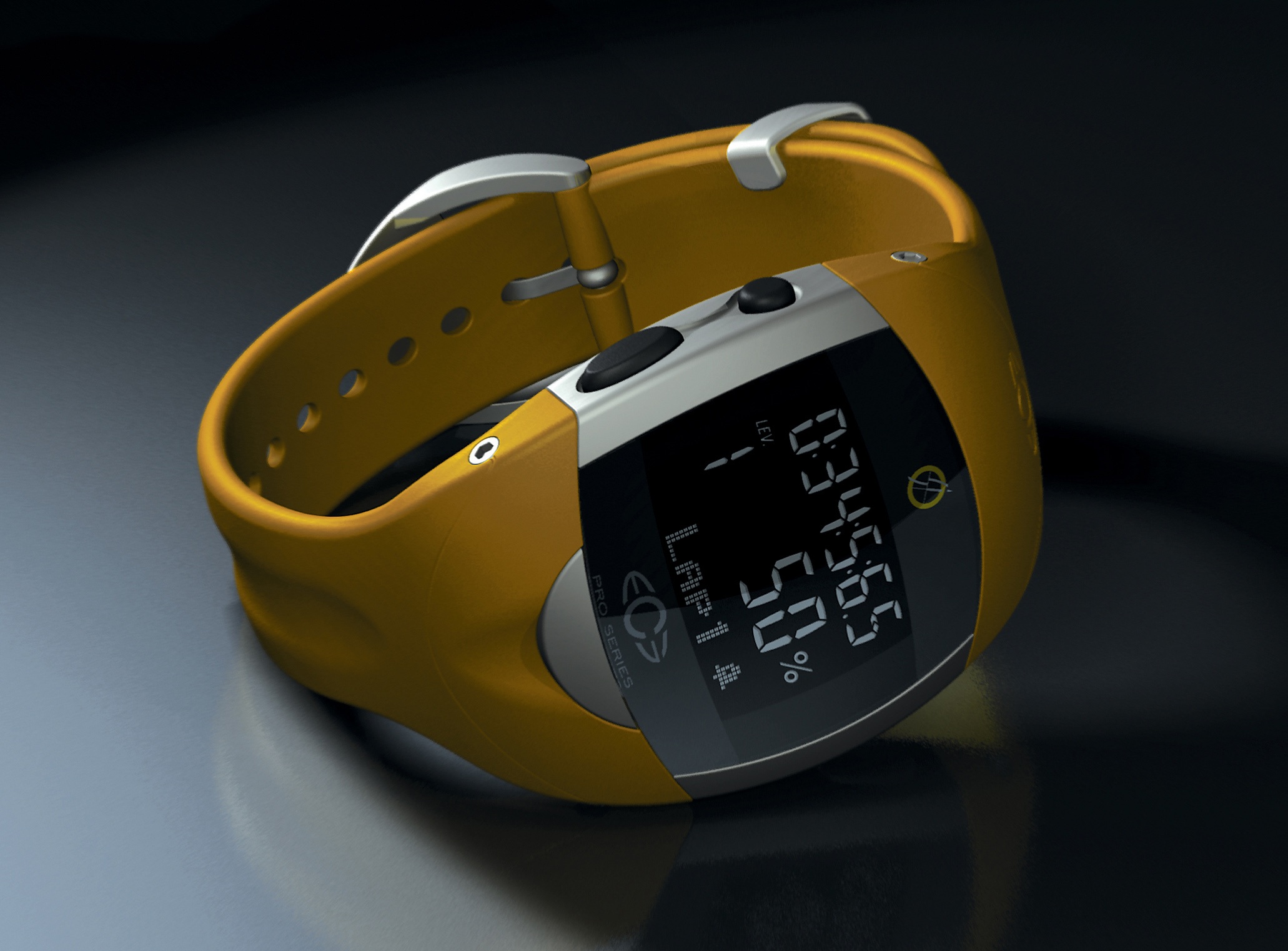
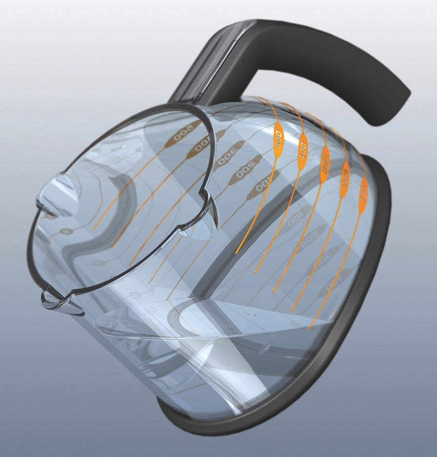
- (*sigh*) Well, everyone is entitled to an opinion, I suppose. As if “facts” matter, the trend for CAD since day-1 has been for increasing realism in their shading and rendering capabilities. That should surprise no one. Realistic rendering allows engineers to design products and show clients what something will look like, like this wrist watch and this measuring cup (both of which were real products for real clients by real designers and engineers). Rendering is an important, central feature for many CAD users to communicate with clients or bosses.
In the CAD stone-ages, all mere mortals could afford was CAD programs that gave them wireframe. Do you think progress stopped there? Then out came flat shading, and Gouraud and Phong shading. Then the various levels of ray-tracing. And this technology is forever becoming more accessible—price-wise and in ease-of-use.
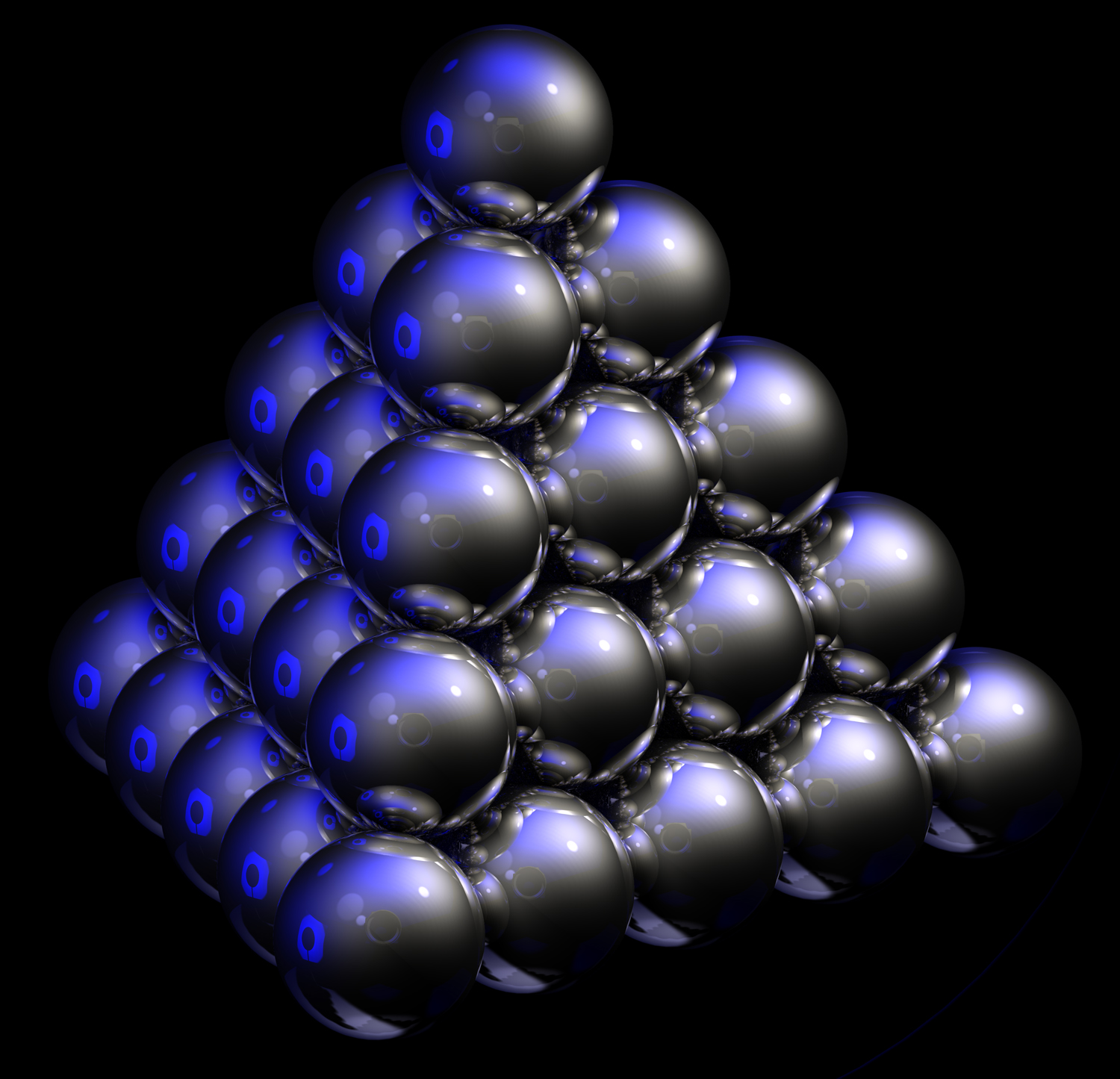
No engineer wants to buy even more software (like thousands of dollars grows on trees) to show a client what their product looks like if the can get impressive results with the CAD program and the solid model that’s already sitting there staring them in the face. Engineers will always desire realistic renderings and will want access to that realism made as easy and fast as possible. It’s called “progress”; rendering is an important feature of CAD and progress will continue on that front—even though you don’t think it is important.
I don’t want any of the above to come across as being hostile to you. I just think it is exceedingly unfortunate that Wikipedia makes it so easy for people with no clearly no expertise whatsoever in a particular technical matter to opine on issues they don’t really understand. If you had stopped at “it isn’t all that impressive,” that would have been fine. But flat stating that rendering realism is “extraneous to the core purpose of CAD” betrays galactic-grade cluelessness of the actual facts. I looked at your user page. I prefer to think that your work towards your degree in engineering physics and your work on other fine, ray-traced graphics like these glass balls on sticks has compromised your objectivity. That’s an impressive rendering you made, by the way. Maybe it is a “resentment” thing (you’re not impressed). Either that, or you really don’t understand CAD. Greg L (talk) 21:41, 17 February 2011 (UTC)
- I'll just let my large team of fellow civil engineers and CAD technicians know that when we create those huge plots in AutoCAD from which we actually build multi-span bridges, we're doing it wrong, according to Greg, and we're not really engineers, on account of, you know, the construction aspect, and that we really don't know how to do computer-aided draughting at all, because we're not ray-tracing and playing with light, but specifying steel and levels and very precise and to-scale measurements. It's fine, I'm sure they'll take it well, just like I have. Maedin\talk 22:32, 17 February 2011 (UTC)
- Then you know full well that bridges and wristwatches are two different things. Phong shading would be fine to illustrate a bridge to a client. Greg L (talk) 23:10, 17 February 2011 (UTC)
- Perhaps it would be more accurate to call designing wristwatches CAID instead of CAD. In engineering CAD, rendering photorealistic images is indeed extraneous to the core purpose. I made the glass balls on sticks just for artistic purposes and they are certainly not suitable for manufacturing; nor are they to scale. Purpy Pupple (talk) 02:22, 18 February 2011 (UTC)
- Interesting observation. That is precisely what Cobalt is good at: Doing the CAID part with seamless, sketching-like ease, while allowing you go full-tilt CAD as you progress. Greg L (talk) 06:21, 18 February 2011 (UTC)
- Perhaps it would be more accurate to call designing wristwatches CAID instead of CAD. In engineering CAD, rendering photorealistic images is indeed extraneous to the core purpose. I made the glass balls on sticks just for artistic purposes and they are certainly not suitable for manufacturing; nor are they to scale. Purpy Pupple (talk) 02:22, 18 February 2011 (UTC)
- Then you know full well that bridges and wristwatches are two different things. Phong shading would be fine to illustrate a bridge to a client. Greg L (talk) 23:10, 17 February 2011 (UTC)
- I'll just let my large team of fellow civil engineers and CAD technicians know that when we create those huge plots in AutoCAD from which we actually build multi-span bridges, we're doing it wrong, according to Greg, and we're not really engineers, on account of, you know, the construction aspect, and that we really don't know how to do computer-aided draughting at all, because we're not ray-tracing and playing with light, but specifying steel and levels and very precise and to-scale measurements. It's fine, I'm sure they'll take it well, just like I have. Maedin\talk 22:32, 17 February 2011 (UTC)
- (*sigh*) Well, everyone is entitled to an opinion, I suppose. As if “facts” matter, the trend for CAD since day-1 has been for increasing realism in their shading and rendering capabilities. That should surprise no one. Realistic rendering allows engineers to design products and show clients what something will look like, like this wrist watch and this measuring cup (both of which were real products for real clients by real designers and engineers). Rendering is an important, central feature for many CAD users to communicate with clients or bosses.
- The reason why ray-tracing isn't standard or typical of CAD is because it is usually extraneous to the core purpose of CAD -- which is to create precise engineering drawings. There is not so much EV in a built-in renderer because far better results can be attained with more standard solutions such as a standalone renderer or a separate rendering plugin. And anyway we already have two FP's made with Cobalt, of which the latter is ray-traced. Purpy Pupple (talk) 19:44, 17 February 2011 (UTC)
- So… Cobalt’s integral ray-tracing capabilities is a strike *against* it, based partly on the observation that it is not even standard or typical of CAD. (Sweeeeet.) Perhaps I should have shown the “line” tool; it’s quite standard and typical of other CAD programs. Greg L (talk) 18:12, 17 February 2011 (UTC)
- Oppose since I forgot to mention that earlier when I said "it's not that impressive...". Purpy Pupple (talk) 19:44, 17 February 2011 (UTC)
- Oppose This really doesn't demonstrate what CAD is about. I studied engineering for a few years, so have some clue. JJ Harrison (talk) 22:44, 17 February 2011 (UTC)
- Support Eye-catching. Draws reader (certainly, my) interest to the associated article. High quality. Attractive. Well-done.--Epeefleche (talk) 04:59, 21 February 2011 (UTC)
- Support A good example of what Cobalt can do, evidently, and thus highly encyclopedic. Adam Cuerden (talk) 09:41, 22 February 2011 (UTC)
Promoted File:Cobalt ray-tracing, high-end coffee tamper.jpg --Makeemlighter (talk) 23:22, 22 February 2011 (UTC)