The South African Railways Class 1E of 1925 was an electric locomotive.
| South African Classes 1E and 1ES | |||||||||||||||||||||||||||||||||||||||||||||||||||||||||||||||
|---|---|---|---|---|---|---|---|---|---|---|---|---|---|---|---|---|---|---|---|---|---|---|---|---|---|---|---|---|---|---|---|---|---|---|---|---|---|---|---|---|---|---|---|---|---|---|---|---|---|---|---|---|---|---|---|---|---|---|---|---|---|---|---|
 Class 1ES no. E145 at Salt River, January 1975 | |||||||||||||||||||||||||||||||||||||||||||||||||||||||||||||||
| |||||||||||||||||||||||||||||||||||||||||||||||||||||||||||||||
| |||||||||||||||||||||||||||||||||||||||||||||||||||||||||||||||
| |||||||||||||||||||||||||||||||||||||||||||||||||||||||||||||||
| |||||||||||||||||||||||||||||||||||||||||||||||||||||||||||||||
Between 1925 and 1945, the South African Railways purchased 172 Class 1E electric locomotives, spread over seven orders. They were the first mainline electric locomotives to be introduced in South Africa.[1][2]
Railways electrification edit
In 1920, following a report and recommendations on electric traction by consulting engineers Merz & McLellan of London, the South African Parliament authorised the electrification of the lines between Durban and Pietermaritzburg in Natal and between Cape Town and Simon's Town on the Cape Peninsula at a cost of £4.4 million.[1]
At the time, there were two routes between Pietermaritzburg and Durban. The newer route with its 1 in 66 (1½%) gradients was chosen for electrification over the older route with its 1 in 33 (3%) gradients. Between Cato Ridge and Durban, electrification necessitated the doubling of the track and the construction of ten tunnels as well as the construction of long stretches of cutting and embankment across difficult terrain.[3]
After it was pointed out that the Natal traffic bottleneck was really above rather than below Pietermaritzburg, electrification in Natal eventually first took place between that city and Glencoe. It was a mountainous 171-mile long (275-kilometre) single-track section which carried heavy mineral traffic towards the port of Durban on an alignment with severe gradients and tight curves where the existing working by steam locomotives became too slow and inefficient to keep up with increasing traffic.[1][4]
Work commenced in 1922 and the first electric train on that section was run in November 1925.The whole section was in full electric operation by January 1927. Electrification of the Simon's Town line commenced in March 1927 and full electric operation was introduced during September 1928. Electrification of the new mainline section from Pietermaritzburg to Durban via Delville Wood was completed in 1936 and the first electrically-hauled passenger train entered Durban station on 2 December of that year. Electrification of the original Natal Government Railways mainline from Rossburgh to Cato Ridge was commenced soon after the new mainline was energised, but during the Second World War the work was halted and not restarted until the late 1950s, eventually being switched on in May 1959.[1][5][6]
Benefits edit
An important consideration in deciding upon the economics of electrification was the potential saving in wage-bills. Electrification would reduce the required crew roster from 300 drivers and stokers to 170 drivers and assistants. In addition it was expected that a large reduction in overtime would be accomplished by increasing the average train speeds from steam traction's 8 miles per hour (13 kilometres per hour) to electric traction's 21 miles per hour (34 kilometres per hour) on the Glencoe to Pietermaritzburg section, with slightly higher future speeds anticipated. It was further estimated that the total capacity of the line would be increased by 60%.[3]
Colenso power station edit
The chosen overhead power supply was 3 kV DC, the highest direct current overhead voltage in use at the time. The Colenso power station was built by the SAR specifically to power this line. The complete electrical system for the section consisted of the coal power station at Colenso which generated three-phase 50 Hz current at 6.6 kV AC, stepped up and distributed at 88 kV AC to twelve automatic substations along the route. The substations were located at an average of about 15 miles (24 kilometres) apart and all but one were supplied at 88 kV by two separate three-phase transmission lines. The one at Colenso was fed 6.6 kV AC directly from the power station.[1][7][8][9]
At the substations, the current was stepped down again to 6.6 kV AC, converted by synchronous motor generators to 3 kV DC and fed to the overhead catenary for use by the electric locomotives. The overhead equipment consisted of a copper catenary which supported a copper contact wire by means of droppers. The track structures were steel lattice masts erected on concrete foundations.[1][7][8][9]
Manufacturers edit
South Africa's first electric locomotive, the Class 1E, entered service in Natal in 1925. The locomotive was designed by Metropolitan-Vickers (Metrovick) of Manchester while the mechanical parts of the unit were approved by, Chief Mechanical Engineer of the South African Railways (SAR) F.R. Collins. At the time, the first batch of 78 Class 1E, Series 1 locomotives constituted the largest order for a single type of electric locomotive to have been placed anywhere in the world. The eventual fleet of 172 locomotives was built for the SAR in seven series by four manufacturers over a period of twenty years.[1][4][10][11]
- Series 1. The first sixty locomotives, numbered in the range from E1 to E60, were built by the Swiss Locomotive & Machine Works (SLM) in 1923 and 1924. The remaining eighteen Series 1 locomotives, numbered in the range from E61 to E78, were built by Metropolitan-Vickers in 1925.[12]
- Series 2. All seventeen locomotives, numbered in the range from E79 to E95, were built by Metropolitan-Vickers in 1925 and 1926 and entered service in 1927. These units were slightly heavier than those of Series 1.[12][13]
- Series 3. Five locomotives, numbered in the range from E98 to E102, were built by Metropolitan-Vickers in 1936. The skipped numbers E96 and E97 were allocated to Class ES locomotives.[12]
- Series 4. Twenty locomotives, numbered in the range from E103 to E122, were built by Metropolitan-Vickers in 1936.[12]
- Series 5. Twenty-two locomotives, numbered in the range from E139 to E160, were built by SLM in 1938. The skipped numbers in the range from E123 to E138 were allocated to Classes ES1, ES, 2E, DS and DS1 locomotives.[12]
- Series 6. Twenty locomotives, numbered in the range from E161 to E180, were built by the Nederlandsche Fabriek van Werktuigen en Spoorwegmaterieel (Werkspoor) in 1938.[12]
- Series 7. Ten locomotives, numbered in the range from E181 to E190, were built by Robert Stephenson & Hawthorns in 1944 and entered service in 1945. These units were built under austerity measures during World War II and, on account of wartime transport difficulties, were shipped in a disassembled condition. Body panels, frames and partitions were crated flat, together with bundles of tubing, copper bus-bar, coils of wire and cable, and general electrical equipment. The bogies were shipped partially assembled. The mechanical erection of these units was done by the Mechanical Engineer at the Pietermaritzburg shops after which the units were towed to Danskraal for the assembly of electrical equipment.[12][13]

Characteristics edit
The locomotives were operated as single units on light local passenger trains, double-headed on mainline passenger trains and light goods trains or triple-headed on heavy goods trains.[1]
Interior layout edit
The interior layout consisted of five compartments.[1]
- The driving cabs at each end contained the control gear, meters, gauges, vacuum brake valves and other equipment and were connected by a side corridor along the right side of the locomotive when looking towards Cab 1.[1]
- The high tension compartment was in the middle of the locomotive and contained the high voltage control switches and resistances, accessed through a sliding door which was both mechanically and electrically interlocked to prevent it being opened while a pantograph was in contact with the overhead catenary.[1]
- A machinery compartment behind each cab housed auxiliary gear such as two motor generator sets, one of 16 kilowatts (21 horsepower) and the other of 28 kilowatts (38 horsepower), each coupled to a blower fan on its shaft for ventilating the main motors. In addition it contained a motor-driven rotary vacuum exhauster, air compressor, air reservoirs for the brakes, low-tension control contactors and resistances for the auxiliaries and battery, together with contactor gear for controlling the field of the larger motor generator.[1][3][14]
The sections of the roof above the compartments and the clerestory roof above the high tension compartment were removable to enable heavy machinery or control gear to be lifted out for repair.[1][3][14]
Orientation edit
These dual cab locomotives had four grilles below the four windows on the equipment side and only two grilles below the centre two windows on the corridor side. When observing the locomotive from the side with four grilles, the no. 1 end would be to the left.[2]
Bogies edit
Like the subsequent Classes 2E, 3E and 4E, the Class 1E had bogie mounted draft gear. It had a Bo+Bo wheel arrangement with an articulated inter-bogie linkage, therefore no train forces were transmitted directly to the locomotive body. The bogie pivot centres were 6,604 millimetres (21 feet 8 inches) apart. One of the bottom pivot centres was fixed while the other was free to move longitudinally to allow for any wear occurring in the articulated coupling between the two bogies.[1][3][11]
Three different cowcatchers were used on Class 1E units. The first six series were delivered with cowcatchers made up of horizontal bars. The Series 7 units were delivered with a plain plate type cowcatcher, but the bogies were sometimes interchanged during overhauls with the result that units from different orders often carried cowcatchers not as originally fitted. In later years, units were often fitted with boiler-tube cowcatchers made up of vertically mounted short pieces of boiler tube, similar to those that were fitted on most South African steam locomotives after World War II.[6][15]
Traction motors edit
The four-pole traction motors each operated at 1.5 kV. They were electrically coupled in pairs, two in series across the 3 kV supply line.[1][3]
Braking edit
The locomotive used air brakes. Air connections between units were arranged in the main reservoir circuit so that air could be supplied to another unit in the event of failure of its compressor. For train braking, it also made use of regenerative braking which enabled higher speeds to be allowed on down grades, while reducing the dependence on the train's vacuum or air braking system and with the collateral benefit of savings in electricity consumption. The usual speeds during regeneration were 14 and 28 miles per hour (23 and 45 kilometres per hour) for goods and passenger working respectively. It was reportedly the first extensive use in regular traffic of electric locomotives equipped for multiple unit operation with regenerative braking.[1][3][4][11][13]
Sanding edit
Sanding was arranged for multiple control with electrically operated sand valves to enable multiple unit coupled locomotives to sand simultaneously.[1]
Lighting edit
Lighting was supplied from a 110 V circuit which was fed by the 16 kilowatts (21 horsepower) generator in parallel with 110 V lead acid batteries. The batteries were mounted in cases suspended underneath the locomotive body between the bogies. This generator also supplied power to the control circuits, exhauster, compressor and cab heaters.[1]
Service edit
Early models bore number plates inscribed in English only. By 1938 when the Series 5 locomotives entered service, Afrikaans had been accepted as South Africa's second official language and new locomotives bore bilingual number plates.
While they were employed mainly in Natal, some of the Class 1E units later also worked on the Witwatersrand and eventually also in the Western Cape. From early 1955, as the new Class 5E began to take over the Natal mainline, several Class 1Es were transferred to the Western Transvaal System to work as haulers on cross-Reef trips to transfer loads from yard to yard. Some of them covered more than 8,000,000 kilometres (5,000,000 miles) during their service lives.[16][17][18]
By the late 1960s some efforts were being made to keep steam locomotives out of the central Durban city areas and North Coast loads would be moved between the Bayhead marshalling yards and Stamford Hill by electric haulers. Steam would work goods trains north from there on the North Coast mainline. By 1969, the line to Stanger had been electrified, allowing Empangeni trains to be worked that far by electric units.[6]
Modification edit
They served in both goods and passenger service. Since their top speed of 72 kilometres per hour (45 miles per hour) was considered too slow for fast passenger service on the mail trains, two Class 1E units, numbers E121 and E122, were modified in 1936 by changing their gear ratio to enable them to run at speeds of up to 90 kilometres per hour (56 miles per hour). This appeared to be the practical limit for this type of electric locomotive.[13][14]
Reclassification edit
All together 35 of the Class 1E locomotives were eventually withdrawn from mainline service, modified and reclassified to Class 1ES for use as shunting locomotives. The modifications included alteration of the resistance grids in the electrical circuit and enlarged and widened cabs, but the gear ratios were not altered. Apart from the wider cabs, the modified Class 1ES locomotives were identifiable by their front windows with slanted upper edges compared to the rectangular front windows of the Class 1E.[11]
Rebuilding edit
In 1964, two of these Class 1ES locomotives were rebuilt to centre-cab Class ES shunting locomotives.[11]
Withdrawal edit
All the Class 1E and Class 1ES locomotives were withdrawn from service by 1990.[2]
Series-specific data edit
The Class 1E builders, works numbers, years of construction and modifications to Classes ES and 1ES are listed in the table. The axle load and adhesive weight as shown under "Specifications" in the infobox may be considered as average figures for the Class 1E since these weights varied between the seven series. In respect of the Series 1 to 6 locomotives, the actual load per axle of each bogie and the total locomotive mass are included in the table below.[2][12][19]
Class |
Series |
Loco no. |
Builder |
Works no. |
Year built |
Axle loads Bogie 1 |
Axle loads Bogie 2 |
Adhesive weight |
Rebuilt to |
|---|---|---|---|---|---|---|---|---|---|
| 1E | 1 | E1 | SLM | 2875 | 1923 | 16 LT 12 cwt (16,900 kg) | 16 LT 13 cwt (16,900 kg) | 66 LT 14 cwt (67,800 kg) | |
| 1E | 1 | E2 | SLM | 2876 | 1923 | 16 LT 12 cwt (16,900 kg) | 16 LT 13 cwt (16,900 kg) | 66 LT 14 cwt (67,800 kg) | |
| 1E | 1 | E3 | SLM | 2877 | 1923 | 16 LT 12 cwt (16,900 kg) | 16 LT 13 cwt (16,900 kg) | 66 LT 14 cwt (67,800 kg) | |
| 1E | 1 | E4 | SLM | 2878 | 1923 | 16 LT 12 cwt (16,900 kg) | 16 LT 13 cwt (16,900 kg) | 66 LT 14 cwt (67,800 kg) | |
| 1E | 1 | E5 | SLM | 2879 | 1923 | 16 LT 12 cwt (16,900 kg) | 16 LT 13 cwt (16,900 kg) | 66 LT 14 cwt (67,800 kg) | |
| 1E | 1 | E6 | SLM | 2880 | 1923 | 16 LT 12 cwt (16,900 kg) | 16 LT 13 cwt (16,900 kg) | 66 LT 14 cwt (67,800 kg) | |
| 1E | 1 | E7 | SLM | 2881 | 1923 | 16 LT 12 cwt (16,900 kg) | 16 LT 13 cwt (16,900 kg) | 66 LT 14 cwt (67,800 kg) | |
| 1E | 1 | E8 | SLM | 2882 | 1923 | 16 LT 12 cwt (16,900 kg) | 16 LT 13 cwt (16,900 kg) | 66 LT 14 cwt (67,800 kg) | |
| 1E | 1 | E9 | SLM | 2883 | 1923 | 16 LT 12 cwt (16,900 kg) | 16 LT 13 cwt (16,900 kg) | 66 LT 14 cwt (67,800 kg) | |
| 1E | 1 | E10 | SLM | 2884 | 1923 | 16 LT 12 cwt (16,900 kg) | 16 LT 13 cwt (16,900 kg) | 66 LT 14 cwt (67,800 kg) | |
| 1E | 1 | E11 | SLM | 2885 | 1923 | 16 LT 12 cwt (16,900 kg) | 16 LT 13 cwt (16,900 kg) | 66 LT 14 cwt (67,800 kg) | |
| 1E | 1 | E12 | SLM | 2886 | 1923 | 16 LT 12 cwt (16,900 kg) | 16 LT 13 cwt (16,900 kg) | 66 LT 14 cwt (67,800 kg) | |
| 1E | 1 | E13 | SLM | 2887 | 1923 | 16 LT 12 cwt (16,900 kg) | 16 LT 13 cwt (16,900 kg) | 66 LT 14 cwt (67,800 kg) | |
| 1E | 1 | E14 | SLM | 2888 | 1923 | 16 LT 12 cwt (16,900 kg) | 16 LT 13 cwt (16,900 kg) | 66 LT 14 cwt (67,800 kg) | |
| 1E | 1 | E15 | SLM | 2889 | 1923 | 16 LT 12 cwt (16,900 kg) | 16 LT 13 cwt (16,900 kg) | 66 LT 14 cwt (67,800 kg) | |
| 1E | 1 | E16 | SLM | 2890 | 1923 | 16 LT 12 cwt (16,900 kg) | 16 LT 13 cwt (16,900 kg) | 66 LT 14 cwt (67,800 kg) | |
| 1E | 1 | E17 | SLM | 2891 | 1923 | 16 LT 12 cwt (16,900 kg) | 16 LT 13 cwt (16,900 kg) | 66 LT 14 cwt (67,800 kg) | |
| 1E | 1 | E18 | SLM | 2892 | 1923 | 16 LT 12 cwt (16,900 kg) | 16 LT 13 cwt (16,900 kg) | 66 LT 14 cwt (67,800 kg) | |
| 1E | 1 | E19 | SLM | 2893 | 1923 | 16 LT 12 cwt (16,900 kg) | 16 LT 13 cwt (16,900 kg) | 66 LT 14 cwt (67,800 kg) | |
| 1E | 1 | E20 | SLM | 2894 | 1923 | 16 LT 12 cwt (16,900 kg) | 16 LT 13 cwt (16,900 kg) | 66 LT 14 cwt (67,800 kg) | |
| 1E | 1 | E21 | SLM | 2895 | 1923 | 16 LT 12 cwt (16,900 kg) | 16 LT 13 cwt (16,900 kg) | 66 LT 14 cwt (67,800 kg) | |
| 1E | 1 | E22 | SLM | 2896 | 1923 | 16 LT 12 cwt (16,900 kg) | 16 LT 13 cwt (16,900 kg) | 66 LT 14 cwt (67,800 kg) | |
| 1E | 1 | E23 | SLM | 2897 | 1923 | 16 LT 12 cwt (16,900 kg) | 16 LT 13 cwt (16,900 kg) | 66 LT 14 cwt (67,800 kg) | |
| 1E | 1 | E24 | SLM | 2898 | 1923 | 16 LT 12 cwt (16,900 kg) | 16 LT 13 cwt (16,900 kg) | 66 LT 14 cwt (67,800 kg) | |
| 1E | 1 | E25 | SLM | 2899 | 1923 | 16 LT 12 cwt (16,900 kg) | 16 LT 13 cwt (16,900 kg) | 66 LT 14 cwt (67,800 kg) | |
| 1E | 1 | E26 | SLM | 2900 | 1923 | 16 LT 12 cwt (16,900 kg) | 16 LT 13 cwt (16,900 kg) | 66 LT 14 cwt (67,800 kg) | |
| 1E | 1 | E27 | SLM | 2901 | 1923 | 16 LT 12 cwt (16,900 kg) | 16 LT 13 cwt (16,900 kg) | 66 LT 14 cwt (67,800 kg) | |
| 1E | 1 | E28 | SLM | 2902 | 1923 | 16 LT 12 cwt (16,900 kg) | 16 LT 13 cwt (16,900 kg) | 66 LT 14 cwt (67,800 kg) | |
| 1E | 1 | E29 | SLM | 2903 | 1923 | 16 LT 12 cwt (16,900 kg) | 16 LT 13 cwt (16,900 kg) | 66 LT 14 cwt (67,800 kg) | |
| 1E | 1 | E30 | SLM | 2904 | 1923 | 16 LT 12 cwt (16,900 kg) | 16 LT 13 cwt (16,900 kg) | 66 LT 14 cwt (67,800 kg) | |
| 1E | 1 | E31 | SLM | 2905 | 1923 | 16 LT 12 cwt (16,900 kg) | 16 LT 13 cwt (16,900 kg) | 66 LT 14 cwt (67,800 kg) | |
| 1E | 1 | E32 | SLM | 2906 | 1923 | 16 LT 12 cwt (16,900 kg) | 16 LT 13 cwt (16,900 kg) | 66 LT 14 cwt (67,800 kg) | |
| 1E | 1 | E33 | SLM | 2907 | 1923 | 16 LT 12 cwt (16,900 kg) | 16 LT 13 cwt (16,900 kg) | 66 LT 14 cwt (67,800 kg) | |
| 1E | 1 | E34 | SLM | 2908 | 1923 | 16 LT 12 cwt (16,900 kg) | 16 LT 13 cwt (16,900 kg) | 66 LT 14 cwt (67,800 kg) | |
| 1E | 1 | E35 | SLM | 2909 | 1923 | 16 LT 12 cwt (16,900 kg) | 16 LT 13 cwt (16,900 kg) | 66 LT 14 cwt (67,800 kg) | |
| 1E | 1 | E36 | SLM | 2910 | 1923 | 16 LT 12 cwt (16,900 kg) | 16 LT 13 cwt (16,900 kg) | 66 LT 14 cwt (67,800 kg) | |
| 1E | 1 | E37 | SLM | 2911 | 1923 | 16 LT 12 cwt (16,900 kg) | 16 LT 13 cwt (16,900 kg) | 66 LT 14 cwt (67,800 kg) | |
| 1E | 1 | E38 | SLM | 2912 | 1923 | 16 LT 12 cwt (16,900 kg) | 16 LT 13 cwt (16,900 kg) | 66 LT 14 cwt (67,800 kg) | |
| 1E | 1 | E39 | SLM | 2913 | 1923 | 16 LT 12 cwt (16,900 kg) | 16 LT 13 cwt (16,900 kg) | 66 LT 14 cwt (67,800 kg) | |
| 1E | 1 | E40 | SLM | 2914 | 1923 | 16 LT 12 cwt (16,900 kg) | 16 LT 13 cwt (16,900 kg) | 66 LT 14 cwt (67,800 kg) | |
| 1E | 1 | E41 | SLM | 2915 | 1923 | 16 LT 12 cwt (16,900 kg) | 16 LT 13 cwt (16,900 kg) | 66 LT 14 cwt (67,800 kg) | |
| 1E | 1 | E42 | SLM | 2916 | 1923 | 16 LT 12 cwt (16,900 kg) | 16 LT 13 cwt (16,900 kg) | 66 LT 14 cwt (67,800 kg) | |
| 1E | 1 | E43 | SLM | 2917 | 1923 | 16 LT 12 cwt (16,900 kg) | 16 LT 13 cwt (16,900 kg) | 66 LT 14 cwt (67,800 kg) | |
| 1E | 1 | E44 | SLM | 2918 | 1923 | 16 LT 12 cwt (16,900 kg) | 16 LT 13 cwt (16,900 kg) | 66 LT 14 cwt (67,800 kg) | |
| 1E | 1 | E45 | SLM | 2919 | 1923 | 16 LT 12 cwt (16,900 kg) | 16 LT 13 cwt (16,900 kg) | 66 LT 14 cwt (67,800 kg) | |
| 1E | 1 | E46 | SLM | 2920 | 1923 | 16 LT 12 cwt (16,900 kg) | 16 LT 13 cwt (16,900 kg) | 66 LT 14 cwt (67,800 kg) | |
| 1E | 1 | E47 | SLM | 2921 | 1923 | 16 LT 12 cwt (16,900 kg) | 16 LT 13 cwt (16,900 kg) | 66 LT 14 cwt (67,800 kg) | |
| 1E | 1 | E48 | SLM | 2922 | 1923 | 16 LT 12 cwt (16,900 kg) | 16 LT 13 cwt (16,900 kg) | 66 LT 14 cwt (67,800 kg) | |
| 1E | 1 | E49 | SLM | 2923 | 1923 | 16 LT 12 cwt (16,900 kg) | 16 LT 13 cwt (16,900 kg) | 66 LT 14 cwt (67,800 kg) | |
| 1E | 1 | E50 | SLM | 2924 | 1923 | 16 LT 12 cwt (16,900 kg) | 16 LT 13 cwt (16,900 kg) | 66 LT 14 cwt (67,800 kg) | |
| 1E | 1 | E51 | SLM | 2925 | 1923 | 16 LT 12 cwt (16,900 kg) | 16 LT 13 cwt (16,900 kg) | 66 LT 14 cwt (67,800 kg) | |
| 1E | 1 | E52 | SLM | 2926 | 1923 | 16 LT 12 cwt (16,900 kg) | 16 LT 13 cwt (16,900 kg) | 66 LT 14 cwt (67,800 kg) | |
| 1E | 1 | E53 | SLM | 2927 | 1923 | 16 LT 12 cwt (16,900 kg) | 16 LT 13 cwt (16,900 kg) | 66 LT 14 cwt (67,800 kg) | |
| 1E | 1 | E54 | SLM | 2928 | 1923 | 16 LT 12 cwt (16,900 kg) | 16 LT 13 cwt (16,900 kg) | 66 LT 14 cwt (67,800 kg) | |
| 1E | 1 | E55 | SLM | 2929 | 1923 | 16 LT 12 cwt (16,900 kg) | 16 LT 13 cwt (16,900 kg) | 66 LT 14 cwt (67,800 kg) | |
| 1E | 1 | E56 | SLM | 2930 | 1923 | 16 LT 12 cwt (16,900 kg) | 16 LT 13 cwt (16,900 kg) | 66 LT 14 cwt (67,800 kg) | |
| 1E | 1 | E57 | SLM | 2931 | 1923 | 16 LT 12 cwt (16,900 kg) | 16 LT 13 cwt (16,900 kg) | 66 LT 14 cwt (67,800 kg) | |
| 1E | 1 | E58 | SLM | 2932 | 1923 | 16 LT 12 cwt (16,900 kg) | 16 LT 13 cwt (16,900 kg) | 66 LT 14 cwt (67,800 kg) | |
| 1E | 1 | E59 | SLM | 2933 | 1923 | 16 LT 12 cwt (16,900 kg) | 16 LT 13 cwt (16,900 kg) | 66 LT 14 cwt (67,800 kg) | |
| 1E | 1 | E60 | SLM | 2934 | 1923 | 16 LT 12 cwt (16,900 kg) | 16 LT 13 cwt (16,900 kg) | 66 LT 14 cwt (67,800 kg) | |
| 1E | 1 | E61 | Metrovick | 1925 | 16 LT 12 cwt (16,900 kg) | 16 LT 13 cwt (16,900 kg) | 66 LT 14 cwt (67,800 kg) | ||
| 1E | 1 | E62 | Metrovick | 1925 | 16 LT 12 cwt (16,900 kg) | 16 LT 13 cwt (16,900 kg) | 66 LT 14 cwt (67,800 kg) | ||
| 1E | 1 | E63 | Metrovick | 1925 | 16 LT 12 cwt (16,900 kg) | 16 LT 13 cwt (16,900 kg) | 66 LT 14 cwt (67,800 kg) | ||
| 1E | 1 | E64 | Metrovick | 1925 | 16 LT 12 cwt (16,900 kg) | 16 LT 13 cwt (16,900 kg) | 66 LT 14 cwt (67,800 kg) | ||
| 1E | 1 | E65 | Metrovick | 1925 | 16 LT 12 cwt (16,900 kg) | 16 LT 13 cwt (16,900 kg) | 66 LT 14 cwt (67,800 kg) | ||
| 1E | 1 | E66 | Metrovick | 1925 | 16 LT 12 cwt (16,900 kg) | 16 LT 13 cwt (16,900 kg) | 66 LT 14 cwt (67,800 kg) | ||
| 1E | 1 | E67 | Metrovick | 1925 | 16 LT 12 cwt (16,900 kg) | 16 LT 13 cwt (16,900 kg) | 66 LT 14 cwt (67,800 kg) | ||
| 1E | 1 | E68 | Metrovick | 1925 | 16 LT 12 cwt (16,900 kg) | 16 LT 13 cwt (16,900 kg) | 66 LT 14 cwt (67,800 kg) | ||
| 1E | 1 | E69 | Metrovick | 1925 | 16 LT 12 cwt (16,900 kg) | 16 LT 13 cwt (16,900 kg) | 66 LT 14 cwt (67,800 kg) | ||
| 1E | 1 | E70 | Metrovick | 1925 | 16 LT 12 cwt (16,900 kg) | 16 LT 13 cwt (16,900 kg) | 66 LT 14 cwt (67,800 kg) | ||
| 1E | 1 | E71 | Metrovick | 1925 | 16 LT 12 cwt (16,900 kg) | 16 LT 13 cwt (16,900 kg) | 66 LT 14 cwt (67,800 kg) | ||
| 1E | 1 | E72 | Metrovick | 1925 | 16 LT 12 cwt (16,900 kg) | 16 LT 13 cwt (16,900 kg) | 66 LT 14 cwt (67,800 kg) | ||
| 1E | 1 | E73 | Metrovick | 1925 | 16 LT 12 cwt (16,900 kg) | 16 LT 13 cwt (16,900 kg) | 66 LT 14 cwt (67,800 kg) | ||
| 1E | 1 | E74 | Metrovick | 1925 | 16 LT 12 cwt (16,900 kg) | 16 LT 13 cwt (16,900 kg) | 66 LT 14 cwt (67,800 kg) | ||
| 1E | 1 | E75 | Metrovick | 1925 | 16 LT 12 cwt (16,900 kg) | 16 LT 13 cwt (16,900 kg) | 66 LT 14 cwt (67,800 kg) | ||
| 1E | 1 | E76 | Metrovick | 1925 | 16 LT 12 cwt (16,900 kg) | 16 LT 13 cwt (16,900 kg) | 66 LT 14 cwt (67,800 kg) | ||
| 1E | 1 | E77 | Metrovick | 1925 | 16 LT 12 cwt (16,900 kg) | 16 LT 13 cwt (16,900 kg) | 66 LT 14 cwt (67,800 kg) | ||
| 1E | 1 | E78 | Metrovick | 1925 | 16 LT 12 cwt (16,900 kg) | 16 LT 13 cwt (16,900 kg) | 66 LT 14 cwt (67,800 kg) | ||
| 1E | 2 | E79 | Metrovick | 1925-26 | 17 LT 4 cwt (17,500 kg) | 17 LT 6 cwt (17,600 kg) | 69 LT 0 cwt (70,100 kg) | ||
| 1E | 2 | E80 | Metrovick | 1925-26 | 17 LT 4 cwt (17,500 kg) | 17 LT 6 cwt (17,600 kg) | 69 LT 0 cwt (70,100 kg) | ||
| 1E | 2 | E81 | Metrovick | 1925-26 | 17 LT 4 cwt (17,500 kg) | 17 LT 6 cwt (17,600 kg) | 69 LT 0 cwt (70,100 kg) | ||
| 1E | 2 | E82 | Metrovick | 1925-26 | 17 LT 4 cwt (17,500 kg) | 17 LT 6 cwt (17,600 kg) | 69 LT 0 cwt (70,100 kg) | ||
| 1E | 2 | E83 | Metrovick | 1925-26 | 17 LT 4 cwt (17,500 kg) | 17 LT 6 cwt (17,600 kg) | 69 LT 0 cwt (70,100 kg) | ||
| 1E | 2 | E84 | Metrovick | 1925-26 | 17 LT 4 cwt (17,500 kg) | 17 LT 6 cwt (17,600 kg) | 69 LT 0 cwt (70,100 kg) | ||
| 1E | 2 | E85 | Metrovick | 1925-26 | 17 LT 4 cwt (17,500 kg) | 17 LT 6 cwt (17,600 kg) | 69 LT 0 cwt (70,100 kg) | ||
| 1E | 2 | E86 | Metrovick | 1925-26 | 17 LT 4 cwt (17,500 kg) | 17 LT 6 cwt (17,600 kg) | 69 LT 0 cwt (70,100 kg) | ||
| 1E | 2 | E87 | Metrovick | 1925-26 | 17 LT 4 cwt (17,500 kg) | 17 LT 6 cwt (17,600 kg) | 69 LT 0 cwt (70,100 kg) | ||
| 1E | 2 | E88 | Metrovick | 1925-26 | 17 LT 4 cwt (17,500 kg) | 17 LT 6 cwt (17,600 kg) | 69 LT 0 cwt (70,100 kg) | ||
| 1E | 2 | E89 | Metrovick | 1925-26 | 17 LT 4 cwt (17,500 kg) | 17 LT 6 cwt (17,600 kg) | 69 LT 0 cwt (70,100 kg) | ||
| 1E | 2 | E90 | Metrovick | 1925-26 | 17 LT 4 cwt (17,500 kg) | 17 LT 6 cwt (17,600 kg) | 69 LT 0 cwt (70,100 kg) | ||
| 1E | 2 | E91 | Metrovick | 1925-26 | 17 LT 4 cwt (17,500 kg) | 17 LT 6 cwt (17,600 kg) | 69 LT 0 cwt (70,100 kg) | ||
| 1E | 2 | E92 | Metrovick | 1925-26 | 17 LT 4 cwt (17,500 kg) | 17 LT 6 cwt (17,600 kg) | 69 LT 0 cwt (70,100 kg) | ||
| 1E | 2 | E93 | Metrovick | 1925-26 | 17 LT 4 cwt (17,500 kg) | 17 LT 6 cwt (17,600 kg) | 69 LT 0 cwt (70,100 kg) | ||
| 1E | 2 | E94 | Metrovick | 1925-26 | 17 LT 4 cwt (17,500 kg) | 17 LT 6 cwt (17,600 kg) | 69 LT 0 cwt (70,100 kg) | ||
| 1E | 2 | E95 | Metrovick | 1925-26 | 17 LT 4 cwt (17,500 kg) | 17 LT 6 cwt (17,600 kg) | 69 LT 0 cwt (70,100 kg) | ||
| 1E | 3 | E98 | Metrovick | 1936 | 16 LT 9 cwt (16,700 kg) | 16 LT 9 cwt (16,700 kg) | 65 LT 16 cwt (66,900 kg) | ||
| 1E | 3 | E99 | Metrovick | 1936 | 16 LT 9 cwt (16,700 kg) | 16 LT 9 cwt (16,700 kg) | 65 LT 16 cwt (66,900 kg) | ||
| 1E | 3 | E100 | Metrovick | 1936 | 16 LT 9 cwt (16,700 kg) | 16 LT 9 cwt (16,700 kg) | 65 LT 16 cwt (66,900 kg) | ||
| 1ES | 3 | E101 | Metrovick | 1936 | 16 LT 9 cwt (16,700 kg) | 16 LT 9 cwt (16,700 kg) | 65 LT 16 cwt (66,900 kg) | 1ES | |
| 1E | 3 | E102 | Metrovick | 1936 | 16 LT 9 cwt (16,700 kg) | 16 LT 9 cwt (16,700 kg) | 65 LT 16 cwt (66,900 kg) | ||
| 1E | 4 | E103 | Metrovick | 1936 | 16 LT 9 cwt (16,700 kg) | 16 LT 9 cwt (16,700 kg) | 65 LT 16 cwt (66,900 kg) | ||
| 1ES | 4 | E104 | Metrovick | 1936 | 16 LT 9 cwt (16,700 kg) | 16 LT 9 cwt (16,700 kg) | 65 LT 16 cwt (66,900 kg) | 1ES | |
| 1ES | 4 | E105 | Metrovick | 1936 | 16 LT 9 cwt (16,700 kg) | 16 LT 9 cwt (16,700 kg) | 65 LT 16 cwt (66,900 kg) | 1ES | |
| 1ES | 4 | E106 | Metrovick | 1936 | 16 LT 9 cwt (16,700 kg) | 16 LT 9 cwt (16,700 kg) | 65 LT 16 cwt (66,900 kg) | 1ES | |
| 1ES | 4 | E107 | Metrovick | 1936 | 16 LT 9 cwt (16,700 kg) | 16 LT 9 cwt (16,700 kg) | 65 LT 16 cwt (66,900 kg) | 1ES | |
| 1ES | 4 | E108 | Metrovick | 1936 | 16 LT 9 cwt (16,700 kg) | 16 LT 9 cwt (16,700 kg) | 65 LT 16 cwt (66,900 kg) | 1ES | |
| 1ES | 4 | E109 | Metrovick | 1936 | 16 LT 9 cwt (16,700 kg) | 16 LT 9 cwt (16,700 kg) | 65 LT 16 cwt (66,900 kg) | 1ES | |
| 1ES | 4 | E110 | Metrovick | 1936 | 16 LT 9 cwt (16,700 kg) | 16 LT 9 cwt (16,700 kg) | 65 LT 16 cwt (66,900 kg) | 1ES | |
| 1ES | 4 | E111 | Metrovick | 1936 | 16 LT 9 cwt (16,700 kg) | 16 LT 9 cwt (16,700 kg) | 65 LT 16 cwt (66,900 kg) | 1ES | |
| 1ES | 4 | E112 | Metrovick | 1936 | 16 LT 9 cwt (16,700 kg) | 16 LT 9 cwt (16,700 kg) | 65 LT 16 cwt (66,900 kg) | 1ES | |
| 1ES | 4 | E113 | Metrovick | 1936 | 16 LT 9 cwt (16,700 kg) | 16 LT 9 cwt (16,700 kg) | 65 LT 16 cwt (66,900 kg) | 1ES | |
| 1ES | 4 | E114 | Metrovick | 1936 | 16 LT 9 cwt (16,700 kg) | 16 LT 9 cwt (16,700 kg) | 65 LT 16 cwt (66,900 kg) | ES E525 | |
| 1ES | 4 | E115 | Metrovick | 1936 | 16 LT 9 cwt (16,700 kg) | 16 LT 9 cwt (16,700 kg) | 65 LT 16 cwt (66,900 kg) | 1ES | |
| 1ES | 4 | E116 | Metrovick | 1936 | 16 LT 9 cwt (16,700 kg) | 16 LT 9 cwt (16,700 kg) | 65 LT 16 cwt (66,900 kg) | 1ES | |
| 1ES | 4 | E117 | Metrovick | 1936 | 16 LT 9 cwt (16,700 kg) | 16 LT 9 cwt (16,700 kg) | 65 LT 16 cwt (66,900 kg) | 1ES | |
| 1ES | 4 | E118 | Metrovick | 1936 | 16 LT 9 cwt (16,700 kg) | 16 LT 9 cwt (16,700 kg) | 65 LT 16 cwt (66,900 kg) | 1ES | |
| 1ES | 4 | E119 | Metrovick | 1936 | 16 LT 9 cwt (16,700 kg) | 16 LT 9 cwt (16,700 kg) | 65 LT 16 cwt (66,900 kg) | 1ES | |
| 1ES | 4 | E120 | Metrovick | 1936 | 16 LT 9 cwt (16,700 kg) | 16 LT 9 cwt (16,700 kg) | 65 LT 16 cwt (66,900 kg) | 1ES | |
| 1ES | 4 | E121 | Metrovick | 1936 | 16 LT 12 cwt (16,900 kg) | 16 LT 12 cwt (16,900 kg) | 66 LT 8 cwt (67,500 kg) | 1ES | |
| 1ES | 4 | E122 | Metrovick | 1936 | 16 LT 12 cwt (16,900 kg) | 16 LT 12 cwt (16,900 kg) | 66 LT 8 cwt (67,500 kg) | 1ES | |
| 1ES | 5 | E139 | SLM | 3655 | 1938 | 16 LT 13 cwt (16,900 kg) | 16 LT 13 cwt (16,900 kg) | 66 LT 12 cwt (67,700 kg) | 1ES |
| 1ES | 5 | E140 | SLM | 3656 | 1938 | 16 LT 13 cwt (16,900 kg) | 16 LT 13 cwt (16,900 kg) | 66 LT 12 cwt (67,700 kg) | 1ES |
| 1ES | 5 | E141 | SLM | 3657 | 1938 | 16 LT 13 cwt (16,900 kg) | 16 LT 13 cwt (16,900 kg) | 66 LT 12 cwt (67,700 kg) | 1ES |
| 1ES | 5 | E142 | SLM | 3658 | 1938 | 16 LT 13 cwt (16,900 kg) | 16 LT 13 cwt (16,900 kg) | 66 LT 12 cwt (67,700 kg) | 1ES |
| 1ES | 5 | E143 | SLM | 3659 | 1938 | 16 LT 13 cwt (16,900 kg) | 16 LT 13 cwt (16,900 kg) | 66 LT 12 cwt (67,700 kg) | 1ES |
| 1ES | 5 | E144 | SLM | 3660 | 1938 | 16 LT 13 cwt (16,900 kg) | 16 LT 13 cwt (16,900 kg) | 66 LT 12 cwt (67,700 kg) | 1ES |
| 1ES | 5 | E145 | SLM | 3661 | 1938 | 16 LT 13 cwt (16,900 kg) | 16 LT 13 cwt (16,900 kg) | 66 LT 12 cwt (67,700 kg) | 1ES |
| 1ES | 5 | E146 | SLM | 3662 | 1938 | 16 LT 13 cwt (16,900 kg) | 16 LT 13 cwt (16,900 kg) | 66 LT 12 cwt (67,700 kg) | ES E526 |
| 1ES | 5 | E147 | SLM | 3663 | 1938 | 16 LT 13 cwt (16,900 kg) | 16 LT 13 cwt (16,900 kg) | 66 LT 12 cwt (67,700 kg) | 1ES |
| 1ES | 5 | E148 | SLM | 3664 | 1938 | 16 LT 13 cwt (16,900 kg) | 16 LT 13 cwt (16,900 kg) | 66 LT 12 cwt (67,700 kg) | 1ES |
| 1ES | 5 | E149 | SLM | 3665 | 1938 | 16 LT 13 cwt (16,900 kg) | 16 LT 13 cwt (16,900 kg) | 66 LT 12 cwt (67,700 kg) | 1ES |
| 1ES | 5 | E150 | SLM | 3666 | 1938 | 16 LT 13 cwt (16,900 kg) | 16 LT 13 cwt (16,900 kg) | 66 LT 12 cwt (67,700 kg) | 1ES |
| 1ES | 5 | E151 | SLM | 3667 | 1938 | 16 LT 13 cwt (16,900 kg) | 16 LT 13 cwt (16,900 kg) | 66 LT 12 cwt (67,700 kg) | 1ES |
| 1E | 5 | E152 | SLM | 3668 | 1938 | 16 LT 13 cwt (16,900 kg) | 16 LT 13 cwt (16,900 kg) | 66 LT 12 cwt (67,700 kg) | |
| 1ES | 5 | E153 | SLM | 3669 | 1938 | 16 LT 13 cwt (16,900 kg) | 16 LT 13 cwt (16,900 kg) | 66 LT 12 cwt (67,700 kg) | 1ES |
| 1E | 5 | E154 | SLM | 3670 | 1938 | 16 LT 13 cwt (16,900 kg) | 16 LT 13 cwt (16,900 kg) | 66 LT 12 cwt (67,700 kg) | |
| 1E | 5 | E155 | SLM | 3671 | 1938 | 16 LT 13 cwt (16,900 kg) | 16 LT 13 cwt (16,900 kg) | 66 LT 12 cwt (67,700 kg) | |
| 1E | 5 | E156 | SLM | 3672 | 1938 | 16 LT 13 cwt (16,900 kg) | 16 LT 13 cwt (16,900 kg) | 66 LT 12 cwt (67,700 kg) | |
| 1ES | 5 | E157 | SLM | 3673 | 1938 | 16 LT 13 cwt (16,900 kg) | 16 LT 13 cwt (16,900 kg) | 66 LT 12 cwt (67,700 kg) | 1ES |
| 1E | 5 | E158 | SLM | 3674 | 1938 | 16 LT 13 cwt (16,900 kg) | 16 LT 13 cwt (16,900 kg) | 66 LT 12 cwt (67,700 kg) | |
| 1E | 5 | E159 | SLM | 3675 | 1938 | 16 LT 13 cwt (16,900 kg) | 16 LT 13 cwt (16,900 kg) | 66 LT 12 cwt (67,700 kg) | |
| 1E | 5 | E160 | SLM | 3676 | 1938 | 16 LT 13 cwt (16,900 kg) | 16 LT 13 cwt (16,900 kg) | 66 LT 12 cwt (67,700 kg) | |
| 1E | 6 | E161 | Werkspoor | 747 | 1938 | 16 LT 13 cwt (16,900 kg) | 16 LT 13 cwt (16,900 kg) | 66 LT 12 cwt (67,700 kg) | |
| 1E | 6 | E162 | Werkspoor | 748 | 1938 | 16 LT 13 cwt (16,900 kg) | 16 LT 13 cwt (16,900 kg) | 66 LT 12 cwt (67,700 kg) | |
| 1E | 6 | E163 | Werkspoor | 749 | 1938 | 16 LT 13 cwt (16,900 kg) | 16 LT 13 cwt (16,900 kg) | 66 LT 12 cwt (67,700 kg) | |
| 1E | 6 | E164 | Werkspoor | 750 | 1938 | 16 LT 13 cwt (16,900 kg) | 16 LT 13 cwt (16,900 kg) | 66 LT 12 cwt (67,700 kg) | |
| 1E | 6 | E165 | Werkspoor | 751 | 1938 | 16 LT 13 cwt (16,900 kg) | 16 LT 13 cwt (16,900 kg) | 66 LT 12 cwt (67,700 kg) | |
| 1E | 6 | E166 | Werkspoor | 752 | 1938 | 16 LT 13 cwt (16,900 kg) | 16 LT 13 cwt (16,900 kg) | 66 LT 12 cwt (67,700 kg) | |
| 1E | 6 | E167 | Werkspoor | 753 | 1938 | 16 LT 13 cwt (16,900 kg) | 16 LT 13 cwt (16,900 kg) | 66 LT 12 cwt (67,700 kg) | |
| 1E | 6 | E168 | Werkspoor | 754 | 1938 | 16 LT 13 cwt (16,900 kg) | 16 LT 13 cwt (16,900 kg) | 66 LT 12 cwt (67,700 kg) | |
| 1E | 6 | E169 | Werkspoor | 755 | 1938 | 16 LT 13 cwt (16,900 kg) | 16 LT 13 cwt (16,900 kg) | 66 LT 12 cwt (67,700 kg) | |
| 1E | 6 | E170 | Werkspoor | 756 | 1938 | 16 LT 13 cwt (16,900 kg) | 16 LT 13 cwt (16,900 kg) | 66 LT 12 cwt (67,700 kg) | |
| 1E | 6 | E171 | Werkspoor | 757 | 1938 | 16 LT 13 cwt (16,900 kg) | 16 LT 13 cwt (16,900 kg) | 66 LT 12 cwt (67,700 kg) | |
| 1E | 6 | E172 | Werkspoor | 758 | 1938 | 16 LT 13 cwt (16,900 kg) | 16 LT 13 cwt (16,900 kg) | 66 LT 12 cwt (67,700 kg) | |
| 1E | 6 | E173 | Werkspoor | 759 | 1938 | 16 LT 13 cwt (16,900 kg) | 16 LT 13 cwt (16,900 kg) | 66 LT 12 cwt (67,700 kg) | |
| 1E | 6 | E174 | Werkspoor | 760 | 1938 | 16 LT 13 cwt (16,900 kg) | 16 LT 13 cwt (16,900 kg) | 66 LT 12 cwt (67,700 kg) | |
| 1E | 6 | E175 | Werkspoor | 761 | 1938 | 16 LT 13 cwt (16,900 kg) | 16 LT 13 cwt (16,900 kg) | 66 LT 12 cwt (67,700 kg) | |
| 1E | 6 | E176 | Werkspoor | 762 | 1938 | 16 LT 13 cwt (16,900 kg) | 16 LT 13 cwt (16,900 kg) | 66 LT 12 cwt (67,700 kg) | |
| 1E | 6 | E177 | Werkspoor | 763 | 1938 | 16 LT 13 cwt (16,900 kg) | 16 LT 13 cwt (16,900 kg) | 66 LT 12 cwt (67,700 kg) | |
| 1E | 6 | E178 | Werkspoor | 764 | 1938 | 16 LT 13 cwt (16,900 kg) | 16 LT 13 cwt (16,900 kg) | 66 LT 12 cwt (67,700 kg) | |
| 1E | 6 | E179 | Werkspoor | 765 | 1938 | 16 LT 13 cwt (16,900 kg) | 16 LT 13 cwt (16,900 kg) | 66 LT 12 cwt (67,700 kg) | |
| 1E | 6 | E180 | Werkspoor | 766 | 1938 | 16 LT 13 cwt (16,900 kg) | 16 LT 13 cwt (16,900 kg) | 66 LT 12 cwt (67,700 kg) | |
| 1E | 7 | E181 | RSH | 7181 | 1944 | ||||
| 1E | 7 | E182 | RSH | 7182 | 1944 | ||||
| 1E | 7 | E183 | RSH | 7183 | 1944 | ||||
| 1E | 7 | E184 | RSH | 7184 | 1944 | ||||
| 1E | 7 | E185 | RSH | 7185 | 1944 | ||||
| 1E | 7 | E186 | RSH | 7186 | 1944 | ||||
| 1E | 7 | E187 | RSH | 7187 | 1944 | ||||
| 1E | 7 | E188 | RSH | 7188 | 1944 | ||||
| 1E | 7 | E189 | RSH | 7189 | 1944 | ||||
| 1E | 7 | E190 | RSH | 7190 | 1944 |
Illustration edit
The main picture shows a Class 1ES locomotive with its enlarged cab and slanted upper edge front windows, while the following pictures illustrate unmodified locomotives.
-
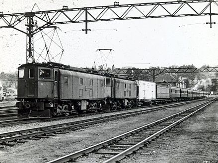 Class 1E double-heading a passenger train in Natal, c. 1930
 -
 Class 1E triple-heading a coal train near Glencoe, c. 1945
 -
 No. E23 plinthed at Union Carriage & Wagon, 24 September 2009
 -
 No. E25 in black, at Danskraal, Ladysmith, 5 December 2010


References edit
- ^ a b c d e f g h i j k l m n o p q r Espitalier, T.J.; Day, W.A.J. (1946). The Locomotive in South Africa - A Brief History of Railway Development. Chapter VII - South African Railways (Continued). South African Railways & Harbours Magazine, March 1946. pp. 205-208.
- ^ a b c d South African Railways Index and Diagrams Electric and Diesel Locomotives, 610 mm and 1065 mm Gauges, Ref LXD 14/1/100/20, 28 January 1975, as amended
- ^ a b c d e f g Mike's Railway History – A Look at Railways in 1935 & Before: South African Electrification (Accessed on 16 May 2016)
- ^ a b c SETS Library - SAR Class 1E Electric Locomotives Sydney Electric Train Society
- ^ Soul of A Railway, System 6, Part 1: Durban Old Station. Caption 15. (Accessed on 8 March 2017)
- ^ a b c Soul of A Railway, System 6, Part 2: Greyville Loco, Greyville Station to Umgeni & Berea Road to Rossburgh. Captions 26, 55, 66, 72, 73. (Accessed on 26 November 2016)
- ^ a b "South African Railways Power Plant". Electric Railway Journal. 60 (24): 914. 9 December 1922. Retrieved 15 September 2010.
- ^ a b Brazil, H (1928). "The South African Railways Electrification". Electrical Substations. Edward Arnold & Co. p. 110. Retrieved 12 January 2010.
- ^ a b Brazil, H (1928). "IX - Traction Substations". Electrical Substations. Edward Arnold and Co. p. 110. Retrieved 15 September 2010.
- ^ "Natal Contract to British". Electric Railway Journal. 61: 107. 13 January 1923. Retrieved 15 September 2010.
- ^ a b c d e Paxton, Leith; Bourne, David (1985). Locomotives of the South African Railways (1st ed.). Cape Town: Struik. p. 125. ISBN 0869772112.
- ^ a b c d e f g h Middleton, John N. (2002). Railways of Southern Africa Locomotive Guide - 2002 (as amended by Combined Amendment List 4, January 2009) (2nd, Dec 2002 ed.). Herts, England: Beyer-Garratt Publications. pp. 4, 50.
- ^ a b c d Espitalier, T.J.; Day, W.A.J. (1946). The Locomotive in South Africa - A Brief History of Railway Development. Chapter VII - South African Railways (Continued). South African Railways & Harbours Magazine, April 1946. pp. 294-296.
- ^ a b c Steam, Oil & Wires, vol 1, (Bernard Zurnamer), pp. 69-71.
- ^ Soul of A Railway, System 6, Part 5: The New Main Line from Rossburgh to Pietermaritzburg compiled by Les Pivnic. Caption 110. (Accessed on 26 August 2017)
- ^ Soul of A Railway, System 7, Western Transvaal, based in Johannesburg, Part 4. Johannesburg to Germiston by Les Pivnic. Caption 28. (Accessed on 28 March 2017)
- ^ December 1922 and March 1925 issues of the Metropolitan-Vickers Gazette
- ^ Electric Traction by A.T. Dover (1929)
- ^ SLM Lokomotiven 1871-1894 by Verein Rollmaterialverzeichnis Schweiz
External links edit
![]() Media related to South African Class 1E at Wikimedia Commons
Media related to South African Class 1E at Wikimedia Commons