This article has multiple issues. Please help improve it or discuss these issues on the talk page. (Learn how and when to remove these template messages)
|
Video Graphics Array (VGA) is a video display controller and accompanying de facto graphics standard, first introduced with the IBM PS/2 line of computers in 1987,[1][2][3] which became ubiquitous in the IBM PC compatible industry within three years.[4] The term can now refer to the computer display standard, the 15-pin D-subminiature VGA connector, or the 640 × 480 resolution characteristic of the VGA hardware.[5]
 | |
| Release date | April 1987 |
|---|---|
| Cards | |
| Entry-level |
|
| Mid-range |
|
| High-end |
|
| History | |
| Predecessor | Enhanced Graphics Adapter |
| Successor | |
VGA was the last IBM graphics standard to which the majority of IBM PC compatible computer manufacturers conformed, making it the lowest common denominator that virtually all post-1990 PC graphics hardware can be expected to implement.[6]
IBM intended to supersede VGA with the Extended Graphics Array (XGA) standard, but failed.[7][failed verification] Instead, VGA was adapted into many extended forms by third parties, collectively known as Super VGA,[8] then gave way to custom graphics processing units which, in addition to their proprietary interfaces and capabilities, continue to implement common VGA graphics modes and interfaces to the present day.
The VGA analog interface standard has been extended to support resolutions of up to 2048 × 1536 and even higher in special applications.[9]
Hardware design edit

The color palette random access memory (RAM) and its corresponding digital-to-analog converter (DAC) were integrated into one chip (the RAMDAC) and the cathode-ray tube controller (CRTC) was integrated into a main VGA chip, which eliminated several other chips in previous graphics adapters, so VGA only additionally required external video RAM and timing crystals.[10][11]
This small part count allowed IBM to include VGA directly on the PS/2 motherboard, in contrast to prior IBM PC models – PC, PC/XT, and PC AT – which required a separate display adapter installed in a slot in order to connect a monitor. The term "array" rather than "adapter" in the name denoted that it was not a complete independent expansion device, but a single component that could be integrated into a system.[12]
Unlike the graphics adapters that preceded it (MDA, CGA, EGA and many third-party options) there was initially no discrete VGA card released by IBM. The first commercial implementation of VGA was a built-in component of the IBM PS/2, in which it was accompanied by 256 KB of video RAM, and a new DE-15 connector replacing the DE-9 used by previous graphics adapters. IBM later released the standalone IBM PS/2 Display Adapter, which utilized the VGA but could be added to machines that did not have it built in.[13][12]
Capabilities edit


The VGA supports all graphics modes supported by the MDA, CGA and EGA cards, as well as multiple new modes.
Standard graphics modes edit
- 640 × 480 in 16 colors or monochrome[14][15]
- 640 × 350 or 640 × 200 in 16 colors or monochrome (EGA/CGA compatibility)
- 320 × 200 in 256 colors (Mode 13h)
- 320 × 200 in 4 or 16 colors (CGA compatibility)
The 640 × 480 16-color and 320 × 200 256-color modes had fully redefinable palettes, with each entry selected from an 18-bit (262,144-color) gamut.[16][17][18][19]
The other modes defaulted to standard EGA or CGA compatible palettes and instructions, but still permitted remapping of the palette with VGA-specific commands.
640 × 480 graphics mode edit
As the VGA began to be cloned in great quantities by manufacturers who added ever-increasing capabilities, its 640 × 480, 16-color mode became the de facto lowest common denominator of graphics cards. By the mid 1990s, a 640 × 480×16 graphics mode using the VGA memory and register specifications was expected by operating systems such as Windows 95 and OS/2 Warp 3.0, which provided no support for lower resolutions or bit depths, or support for other memory or register layouts without additional drivers. Well into the 2000s, even after the VESA standard for graphics cards became commonplace, the "VGA" graphics mode remained a compatibility option for PC operating systems.
Other graphics modes edit
Nonstandard display modes can be implemented, with horizontal resolutions of:
- 512 to 800 pixels wide, in 16 colors
- 256 to 400 pixels wide, in 256 colors
And heights of:
- 200, or 350 to 410 lines (including 400-line) at 70 Hz refresh rate, or
- 224 to 256, or 448 to 512 lines (including 240 or 480-line) at 60 Hz refresh rate
- 512 to 600 lines at reduced vertical refresh rates (down to 50 Hz, and including e.g. 528, 544, 552, 560, 576-line), depending on individual monitor compatibility.
For example, high resolution modes with square pixels are available at 768 × 576 or 704 × 528 in 16 colors, or medium-low resolution at 320 × 240 with 256 colors. Alternatively, extended resolution is available with "fat" pixels and 256 colors using, e.g. 400 × 600 (50 Hz) or 360 × 480 (60 Hz), and "thin" pixels, 16 colors and the 70 Hz refresh rate with e.g. 736 × 410 mode.
"Narrow" modes such as 256 × 224 tend to preserve the same pixel ratio as in e.g. 320 × 240 mode unless the monitor is adjusted to stretch the image out to fill the screen, as they are derived simply by masking down the wider mode instead of altering pixel or line timings, but can be useful for reducing memory requirements and pixel addressing calculations for arcade game conversions or console emulators.
The PC version of Pinball Fantasies has the option to use non-standard modes "high res" modes, such as 640 × 350, allowing it to display a larger portion of the pinball table on screen.[20]
Standard text modes edit
VGA also implements several text modes:
- 80 × 25, rendered with a 9 × 16 pixel font, with an effective resolution of 720 × 400[21]
- 40 × 25, with a 9 × 16 font, with an effective resolution of 360 × 400
- 80 × 43 or 80 × 50, with an 8 × 8 font grid, with an effective resolution of 640 × 344 or 640 × 400 pixels.
As with the pixel-based graphics modes, additional text modes are possible by programming the VGA correctly, with an overall maximum of about 100 × 80 cells and an active area spanning about 88 × 64 cells.
One variant that is sometimes seen is 80 × 30 or 80 × 60, using an 8 × 16 or 8 × 8 font and an effective 640 × 480 pixel display, which trades use of the more flickery 60 Hz mode for an additional 5 or 10 lines of text and square character blocks (or, at 80 × 30, square half-blocks).
Technical details edit
Unlike the cards that preceded it, which used binary TTL signals to interface with a monitor (and also composite, in the case of the CGA), the VGA introduced a video interface using pure analog RGB signals, with a range of 0.7 volts peak-to-peak max. In conjunction with a 18-bit RAMDAC (6-bit per RGB channel), this produced a color gamut of 262,144 colors.[16][17][18][19]
The original VGA specifications follow:
- Selectable 25.175 MHz[22] or 28.322 MHz master pixel clock
- Maximum of 640 horizontal pixels[23] in graphics mode, and 720 pixels in text mode
- Maximum of 480 lines[23]
- Refresh rates at 60 or 70 Hz[24]
- Vertical blank interrupt (Not all clone cards support this.)
- Planar mode: up to 16 colors (4 bit planes)
- Packed-pixel mode: 256 colors (Mode 13h)
- Hardware smooth scrolling support
- No Blitter
- Supports fast data transfers via "VGA latch" registers
- Barrel shifter
- Split screen support
Signal timings edit
The intended standard value for the horizontal frequency of VGA's 640 × 480 mode is exactly double the value used in the NTSC-M video system, as this made it much easier to offer optional TV-out solutions or external VGA-to-TV converter boxes at the time of VGA's development. It is also at least nominally twice that of CGA, which also supported composite monitors.
All derived VGA timings (i.e. those which use the master 25.175 and 28.322 MHz crystals and, to a lesser extent, the nominal 31.469 kHz line rate) can be varied by software that bypasses the VGA firmware interface and communicates directly with the VGA hardware, as many MS-DOS based games did. However, only the standard modes, or modes that at least use almost exactly the same H-sync and V-sync timings as one of the standard modes, can be expected to work with the original late-1980s and early-1990s VGA monitors. The use of other timings may in fact damage such monitors and thus was usually avoided by software publishers.
Third-party "multisync" CRT monitors were more flexible, and in combination with "super EGA", VGA, and later SVGA graphics cards using extended modes, could display a much wider range of resolutions and refresh rates at arbitrary sync frequencies and pixel clock rates.
For the most common VGA mode (640 × 480, 60 Hz, non-interlaced), the horizontal timings can be found in the HP Super VGA Display Installation Guide and in other places.[25][26]
Typical uses of selected modes edit
640 × 400 @ 70 Hz is traditionally the video mode used for booting VGA-compatible x86 personal computers[27] that show a graphical boot screen, while text-mode boot uses 720 × 400 @ 70 Hz.
This convention has been eroded in recent years, however, with POST and BIOS screens moving to higher resolutions, taking advantage of EDID data to match the resolution to a connected monitor.
640 × 480 @ 60 Hz is the default Windows graphics mode (usually with 16 colors),[27] up to Windows 2000. It remains an option in XP and later versions via the boot menu "low resolution video" option and per-application compatibility mode settings, despite newer versions of Windows now defaulting to 1024 × 768 and generally not allowing any resolution below 800 × 600 to be set.
The need for such a low-quality, universally compatible fallback has diminished since the turn of the millennium, as VGA-signalling-standard screens or adaptors unable to show anything beyond the original resolutions have become increasingly rare.
320 × 200 at 70 Hz was the most common mode for VGA-era PC games, with pixel-doubling and line-doubling performed in hardware to present a 640 × 400 at 70 Hz signal to the monitor.
The Windows 95/98/Me LOGO.SYS boot-up image was 320 × 400 resolution, displayed with pixel-doubling to present a 640 × 400 at 70 Hz signal to the monitor. The 400-line signal was the same as the standard 80 × 25 text mode, which meant that pressing Esc to return to text mode didn't change the frequency of the video signal, and thus the monitor did not have to resynchronize (which could otherwise have taken several seconds).
Connector edit
-
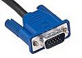 A D-SUB connector (better known as VGA connector
 -
 VGA BNC connectors


The standard VGA monitor interface is a 15-pin D-subminiature connector in the "E" shell, variously referred to as "DE-15", "HD-15" and erroneously "DB-15(HD)".
Because VGA uses low-voltage analog signals, signal degradation becomes a factor with low-quality or overly long cables. Solutions include shielded cables, cables that include a separate internal coaxial cable for each color signal, and "broken out" cables utilizing a separate coaxial cable with a BNC connector for each color signal.
BNC breakout cables typically use five connectors, one each for Red, Green, Blue, Horizontal Sync, and Vertical Sync, and do not include the other signal lines of the VGA interface. With BNC, the coaxial wires are fully shielded end-to-end and through the interconnect so that virtually no crosstalk and very little external interference can occur.
Color palette edit
The VGA color system uses register-based palettes to map colors in various bit depths to its 18-bit output gamut. It is backward compatible with the EGA and CGA adapters, but supports extra bit depth for the palette when in these modes.
For instance, when in EGA 16-color modes, VGA offers 16 palette registers, and in 256-color modes, it offers 256 registers.[28] Each palette register contain a 3×6 bit RGB value, selecting a color from the 18-bit gamut of the DAC.
These color registers are initialized to default values IBM expected to be most useful for each mode. For instance, EGA 16-color modes initialize to the default CGA 16-color palette, and the 256-color mode initializes to a palette consisting of 16 CGA colors, 16 grey shades, and then 216 colors chosen by IBM to fit expected use cases.[29][30] After initialization they can be redefined at any time without altering the contents of video RAM, permitting palette cycling.
-
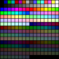 VGA 256 default color palette
 -
 VGA palette organised into 4 groups
 -
 Examples of VGA images in 640×480 with 16 colors and 320×200 with 256 colors (bottom). Dithering is used to mask color limitations.


In the 256-color modes, the DAC is set to combine four 2-bit color values, one from each plane, into an 8-bit-value representing an index into the 256-color palette. The CPU interface combines the 4 planes in the same way, a feature called "chain-4", so that each pixel appears to the CPU as a packed 8-bit value representing the palette index.[31]
Use edit
The video memory of the VGA is mapped to the PC's memory via a window in the range between segments 0xA0000 and 0xBFFFF in the PC's real mode address space (A000:0000 and B000:FFFF in segment:offset notation). Typically, these starting segments are:
- 0xA0000 for EGA/VGA graphics modes (64 KB)
- 0xB0000 for monochrome text mode (32 KB)
- 0xB8000 for color text mode and CGA-compatible graphics modes (32 KB)
Due to the use of different address mappings for different modes, it is possible to have a monochrome adapter (i.e. MDA or Hercules) and a color adapter such as the VGA, EGA, or CGA installed in the same machine.
At the beginning of the 1980s, this was typically used to display Lotus 1-2-3 spreadsheets in high-resolution text on a monochrome display and associated graphics on a low-resolution CGA display simultaneously. Many programmers also used such a setup with the monochrome card displaying debugging information while a program ran in graphics mode on the other card. Several debuggers, like Borland's Turbo Debugger, D86 and Microsoft's CodeView could work in a dual monitor setup. Either Turbo Debugger or CodeView could be used to debug Windows.
There were also device drivers such as ox.sys, which implemented a serial interface simulation on the monochrome display and, for example, allowed the user to receive crash messages from debugging versions of Windows without using an actual serial terminal.
It is also possible to use the "MODE MONO" command at the command prompt to redirect the output to the monochrome display. When a monochrome adapter was not present, it was possible to use the 0xB000–0xB7FF address space as additional memory for other programs.
Programming edit
"Unchaining" the 256 KB VGA memory into four separate "planes" makes VGA's 256 KB of RAM available in 256-color modes. There is a trade-off for extra complexity and performance loss in some types of graphics operations, but this is mitigated by other operations becoming faster in certain situations:
- Single-color polygon filling could be accelerated due to the ability to set four pixels with a single write to the hardware.
- The video adapter could assist in copying video RAM regions, which was sometimes faster than doing this with the relatively slow CPU-to-VGA interface.
- The use of multiple video pages in hardware allowed double buffering, triple buffering or split screens, which, while available in VGA's 320 × 200 16-color mode, was not possible using stock Mode 13h.
- Most particularly, several higher, arbitrary-resolution display modes were possible, all the way up to the programmable limit of 800 × 600 with 16 colors (or 400 × 600 with 256 colors), as well as other custom modes using unusual combinations of horizontal and vertical pixel counts in either color mode.
Software such as Fractint, Xlib and ColoRIX also supported tweaked 256-color modes on standard adaptors using freely-combinable widths of 256, 320, and 360 pixels and heights of 200, 240 and 256 (or 400, 480 and 512) lines, extending still further to 384 or 400 pixel columns and 576 or 600 (or 288, 300). However, 320 × 240 was the best known and most frequently used, as it offered a standard 40-column resolution and 4:3 aspect ratio with square pixels. "320 × 240 × 8" resolution was commonly called Mode X, the name used by Michael Abrash when he presented the resolution in Dr. Dobb's Journal.
The highest resolution modes were only used in special, opt-in cases rather than as standard, especially where high line counts were involved. Standard VGA monitors had a fixed line scan (H-scan) rate – "multisync" monitors being, at the time, expensive rarities – and so the vertical/frame (V-scan) refresh rate had to be reduced in order to accommodate them, which increased visible flicker and thus eye strain. For example, the highest 800 × 600 mode, being otherwise based on the matching SVGA resolution (with 628 total lines), reduced the refresh rate from 60 Hz to about 50 Hz (and 832 × 624, the theoretical maximum resolution achievable with 256 KB at 16 colors, would have reduced it to about 48 Hz, barely higher than the rate at which XGA monitors employed a double-frequency interlacing technique to mitigate full-frame flicker).
These modes were also outright incompatible with some monitors, producing display problems such as picture detail disappearing into overscan (especially in the horizontal dimension), vertical roll, poor horizontal sync or even a complete lack of picture depending on the exact mode attempted. Due to these potential issues, most VGA tweaks used in commercial products were limited to more standards-compliant, "monitor-safe" combinations, such as 320 × 240 (square pixels, three video pages, 60 Hz), 320 × 400 (double resolution, two video pages, 70 Hz), and 360 × 480 (highest resolution compatible with both standard VGA monitors and cards, one video page, 60 Hz) in 256 colors, or double the horizontal resolution in 16-color mode.
Hardware manufacturers edit
Several companies produced VGA compatible graphic board models.[32]
- ATI: Graphics Solution Plus, Wonder series, Mach series
- S3 Graphics: S3 911, 911A, 924, 801, 805, 805i, 928, 805p, 928p, S3 Vision series, S3 Trio series
- Matrox: MAGIC RGB
- Plantronics: Colorplus
- Paradise Systems: PEGA 1, PEGA 1a, PEGA 2a
- Tseng Labs: ET3000, ET4000, ET6000
- Cirrus Logic: CL-GD400, CL-GD500 and CL-GD5000 series
- Trident Microsystems: TVGA 8000 series, TVGA 9000 series, TGUI9000 series
- IIT
- NEC
- Chips and Technologies
- SiS
- Tamerack
- Realtek
- Oak Technology
- LSI
- Hualon
- Cornerstone Imaging
- Winbond
- AMD
- Western Digital
- Intergraph
- Texas Instruments
- Gemini (defunct)
- Genoa Systems (defunct)
Successors edit
Super VGA (SVGA) edit
Super VGA (SVGA) is a display standard developed in 1988, when NEC Home Electronics announced its creation of the Video Electronics Standards Association (VESA). The development of SVGA was led by NEC, along with other VESA members including ATI Technologies and Western Digital. SVGA enabled graphics display resolutions up to 800 × 600 pixels, 36% more than VGA's maximum resolution of 640 × 480 pixels.[33]
Extended Graphics Array (XGA) edit
Extended Graphics Array (XGA) is an IBM display standard introduced in 1990. Later it became the most common appellation of the 1024 × 768 pixels display resolution.
See also edit
- VGA text mode
- Graphic display resolutions
- List of color palettes
- List of video connectors
- List of monochrome and RGB color formats
- List of 16-bit computer hardware palettes
- List of defunct graphics chips and card companies
- Super VGA
- AX-VGA (for Japanese AX architecture computers)
- DOS/V
- DisplayPort and HDMI (which have largely replaced VGA)
References edit
- ^ Petzold, Charles (July 1987). "Triple standard: three new video modes from IBM". PC Magazine. Ziff Davis. Retrieved 2020-04-13.
- ^ Polsson, Ken. "Chronology of IBM Personal Computers". Archived from the original on 2015-02-21. Retrieved 2015-01-28.
- ^ "What is VGA (Video Graphics Array)?". Retrieved 2018-08-13.
- ^ Enterprise, I. D. G. (1990-10-22). Computerworld. IDG Enterprise.
- ^ "Drawing In Protected Mode". OSDev Wiki. Retrieved 2020-12-20.
- ^ Dr. Jon Peddie (12 March 2019). "Famous Graphics Chips: IBM's VGA. The VGA was the most popular graphics chip ever". Retrieved 2020-04-13.
It is said about airplanes that the DC3 and 737 are the most popular planes ever built, and the 737, in particular, the best-selling airplane ever. The same could be said for the ubiquitous VGA, and its big brother the XGA. The VGA, which can still be found buried in today's modern GPUs and CPUs, set the foundation for a video standard, and an application programming standard.
- ^ Corcoran, Cate (February 5, 1996). "Guarded view of Big Blue". InfoWorld. p. 53.
- ^ Eckert; Azinger (April 15, 1991). "Product Comparison - Super VGA Boards". InfoWorld. pp. 53–63.
- ^ Magazines, S. P. H. (April 2007). HWM. SPH Magazines.
- ^ Peddie, Jon (12 March 2019). "Famous Graphics Chips: IBM's VGA | IEEE Computer Society". IEEE Computer Society. Archived from the original on 2022-11-28. Retrieved 2022-12-27.
- ^ Thompson, Stephen (1988). "VGA ‒ Design choices for a new video subsystem". IBM Systems Journal. 27 (2). IBM: 185‒197. doi:10.1147/sj.272.0185.
- ^ a b Rosch, Winn (December 22, 1987). "IBM VGA Adapter Card: 256K Video RAM, 17 Display Modes". PC Magazine. p. 35.
- ^ "THE IBM PERSONAL SYSTEM/2 (TM) DISPLAY ADAPTER, THE IBM PERSONAL SYSTEM/2 DISPLAY ADAPTER 8514/A AND". www-01.ibm.com. 1987-04-02. Retrieved 2020-08-16.
- ^ Hinner, Martin. "VGA Timings". Archived from the original on 27 October 2012. Retrieved 7 November 2012.
- ^ "Drawing In Protected Mode - OSDev Wiki". wiki.osdev.org. Retrieved 2020-12-20.
- ^ a b US5574478A, Bril, Vlad & Pett, Boyd G., "VGA color system for personal computers", issued 1996-11-12
- ^ a b "Reading and writing 18-bit RGB VGA Palette (pal) files with C#". The Cyotek Blog. 2017-12-26. Retrieved 2023-03-27.
- ^ a b "VGA/SVGA Video Programming--Color Regsters". www.osdever.net. Retrieved 2023-03-27.
- ^ a b "VGA Palette Conversion \ VOGONS". www.vogons.org. Retrieved 2023-03-27.
- ^ "Late PCI, early and middle AGP video chips DOS game compatibility test results". archive.ph. Archived from the original on 2022-03-21.
- ^ Abrash, Michael. "How 360×480 in 256 color mode works". Graphics Programming Black Book. Archived from the original on 23 April 2012. Retrieved 7 November 2012.
- ^ "VGA Signal 640 x 480 @ 60 Hz Industry standard timing". www.tinyvga.com.
- ^ a b PS/2 Video Subsystem Technical Reference Manual 1992
- ^ "VGA Signal timings". Archived from the original on 2016-06-20.
- ^ "Javier Valcarce VGA timings page". Archived from the original on 2015-01-02.
- ^ HP D1194A Super VGA Display & HP D1195A Ergonomic Super VGA Display Installation Guide, Hewlett Packard
- ^ a b "ePanorama.net - Circuits". Archived from the original on 2009-02-27. 090425 epanorama.net
- ^ "VGA/SVGA Video Programming--Color Regsters". www.scs.stanford.edu. Retrieved 2020-08-16.
- ^ IBM PS/2 Hardware Interface Technical Reference Manual (PDF). pp. 13–18.
- ^ retrocomputing SE question: why-were-those-colors-chosen-to-be-the-default-palette-for-256-color-vga ?
- ^ Uphoff, Matthias (1990). Die Programmierung der EGA/VGA Grafikkarte; ISBN 3-89319-274-3; this whole section was learned from this book
- ^ "The History of the Modern Graphics Processor". techspot.com. Archived from the original on 29 March 2016. Retrieved 6 May 2018.
- ^ Brownstein, Mark (November 14, 1988). "NEC Forms Video Standards Group". InfoWorld. Vol. 10, no. 46. p. 3. ISSN 0199-6649. Retrieved May 27, 2016.
Further reading edit
- J. D. Neal (1997). "VGA Chipset Reference". Hardware Level VGA and SVGA Video Programming Information Page.
- Jordan Brown and John Kingman (6 May 1996). "CHRP VGA Display Device Binding to IEEE 1275–1994 Standard for Boot (Initialization, Configuration) Firmware". 1.0. Archived from the original on 9 September 2006. Retrieved 22 June 2006.
{{cite journal}}: Cite journal requires|journal=(help) - Hinner. "VGA Interface and video signal documents". Signal Level VGA and SVGA Video Information Page.
- "IBM VGA Technical Reference Manual" (PDF). This is the original IBM reference. The document provides good overview of VGA functionality and is fairly complete, including a detailed description of standard BIOS modes and some programming techniques.