This is an archive of past discussions. Do not edit the contents of this page. If you wish to start a new discussion or revive an old one, please do so on the current talk page.
Latest comment: 10 years ago6 comments3 people in discussion
I work in quantum optics and I am kind of shocked when looking at the state of this article. Much of what is claimed here is plain wrong like the claim that "The experiment can also be explained with classical waves, but with another conclusion." for the DCQE using entangled photons. There obviously are no classical entangled photons. It is also generally agreed upon that all the consequences of entanglement cannot be explained classically. That part of the article also does not cite any references and is not acceptable the way it is. Also many of the recent changes introduced odd wordings ("This Delayed quantum eraser claimes to be a real double-slit measurement.", "If the photon is recorded at detector D1 or D2, it has a 50% chance to be a "blue" photon and 50% chance to be a "red" one.") or sloppy wordings ("A Quantum eraser which often used in education is based on placing two orthogonal polarizers at the slits of a Double slit experiment, causing the interference to disappear. ") and the article is very incoherent. Right now, it more or less reads like pushing crackpot agenda. In my opinion the last acceptable version was the one from 07:41, 1 October 2013 by Rursus. As I am not actively editing Wikipedia, I will leave the decision to others, but in my opinion the article should be reversed to that state. 129.217.159.124 (talk) 12:56, 30 January 2014 (UTC)
I have to agree with you. I have tried to work with DParlevliet without being able to convince him that there are problems with what he has written. I'm involved in other things that are taking up lots of time right now.
Anyone who makes substantial changes to established articles should be willing to discuss the changes and convince those who have already spent a great deal of time and trouble to make the clearest explanation possible that the change proposed actually improves the article.
I, too, am in favor of reverting to the 1 October 2013 version.P0M (talk) 01:19, 31 January 2014 (UTC)
I have been adding parts bit by bit and got no remarks until now. But perhaps I went too fast. With POM I had a misunderstanding but no remarks or discussion about the latest parts. According Wiki rules edits should not be deleted but discussed and improved. I know the classical way is controversial, and if it is wrong I will change it. But then with arguments. Not just "classical is wrong" by definition. If words are sloppy, change it, that is Wiki-style. There are several parts changed, most just to compress multiple or not relevant explanation without change of description. There are several experiments added and combined with another article and with most also is mentioned if it can be classical explained or not. This is with simple High-School goniometry which does not reference I suppose. So if someone has remarks about specific parts, please mention where and discuss. DParlevliet (talk) 10:56, 1 February 2014 (UTC)
It is somewhat hard to take that comment seriously as you deleted major parts of a reasonably well written article yourself without discussing beforehand. Do you have any peer-reviewed references backing your point of view? If so, there is something to discuss. Otherwise in my opinion the old version of the article should be restored and kept.129.217.159.124 (talk) 14:39, 3 February 2014 (UTC)
To add to what I just wrote. Sections like " So 2 is not an absence of interference, but the sum of two interference patterns which are shifted 180°." are a good example of what is wrong with the article. any non-interference pattern seen when using both slits can be decomposed into several interference patterns. A double slit measures spatial coherence. Or simply speaking a light field with narrow angular spread will show an interference pattern. A light source with large angular spread will not. One can easily check that by taking a light source and placing it closer to the double slit. At some distance the pattern will vanish. If one wants to, one can now filter that light source and allow only the emission from one tiny spot on the surface of the emitter to pass through the double slit. The pattern will reappear. If one repeats that for every tiny spot on the surface of the emitter, one gets different patterns for every spot on the sample. They will in total sum up to no pattern at all. This IS the absence of interference. 129.217.159.124 (talk) 14:49, 3 February 2014 (UTC)
Note that there has been no response. P0M (talk) 18:57, 8 February 2014 (UTC)
Delayed quantum eraser of Walborn e.a in classical way
Latest comment: 10 years ago20 comments3 people in discussion
From 129.217.159.124 I understand he objects to this part. What is wrong here? It is just an explanation following strict and simple classical rules. Because entanglement is not classical, it is not used here. Only that the polarization of POL determines the polarization before Q1/Q2, and that was from the article of Walborn. I will make a reference of that. DParlevliet (talk) 11:16, 1 February 2014 (UTC)
I will let 129.217.159.124 respond since he has his own set of questions. Actually, I think he already told you. Have you read and tried to understand his criticisms?
Since you have brought up this one section for examination, however, I would like to ask you why you cite a document that it costs money to acquire instead of arXiv:quant-ph/0106078v1 13 Jun 2001? (http://www.arxiv.org/pdf/quant-ph/0106078%E2%80%8E).
Second, I would like to understand why you begin by casting doubt on the qualifications of a number of physicists with responsible positions in universities by saying, "This Delayed quantum eraser claimes to be a real double-slit measurement." The sentence does not exhibit proper syntax, but the "claims to be," to which I have added emphasis, displays a clear rhetorical intent. We owe individuals who have spent decades of study to achieve their high level of competence some modicum of respect. As for the syntax, erasers can't make any claims. You appear to be talking about the experiment and about what several people claim it to be.
In the beginning period of the development of quantum mechanics the Copenhagen group had a clearly articulated understanding that anything that was well explained in classical physics could not acceptably have an explanation of inferior predictive power in quantum physics. Or, to put it another way, all of classical physics that was correct would be found to be subsumed in quantum physics. The unsuccessful parts of it, such as attempts to explain heat and radiation that led to the Ultraviolet catastrophe, would be replaced by entirely new explanations, and then there were some items of theory that were not even mentioned in classical physics. Unless somebody comes up with a mistake in quantum mechanics that blows it up and leaves classical physics standing or revived, there cannot be one explanation according to quantum mechanics and an equal contender in line with classical physics that is equally acceptable or superior.P0M (talk) 02:58, 2 February 2014 (UTC)
I have answered 129.217.159.124 above. The document reference I have take over from quantum eraser, with I merged in this article. The "claim" had no rhetorical intent, but the article itself claimed that this was the first real double slit. Because it can be misunderstood (and is not so relevant) I will remove it. Copenhagen mentioned that photond has wave properties, until a limit. There is no harm giving also a classical explanation and mention where is differs from QM, so where is its limit (or the description of the article). Look to double slit experiment, which has a separate classical part, and I just did the same in this article. Take into account that most readers will understand classical waves much better then QM formula, but it must be right. So if something in the description is wrong, please mention. Anyway I will change it to be less defiant. DParlevliet (talk) 13:11, 2 February 2014 (UTC)
You say:
In 2 the incoming polarization can be resolve in two polarizations on the F and S axis, which each give the same result as 3 en 4. So 2 is not an absence of interference, but the sum of two interference patterns which are shifted 180°.
This statement is clearly wrong.
There is nothing significantly different, for this experiment, between a classical understanding of polarization and a quantum mechanical understanding of it. In other words, for the purpose of understanding this experiment we need only know what the various polarizations are, and how they determine the observed results. We do not need to get into explanations of how polarization occurs.
The important quantum mechanical features of this experiment are: (1) the fact that entangled photons can be created, and that when photons are entangled they must retain certain correlations, and (2) the way that photons passing through a double-slit diaphragm behave, something that is already in fairly substantial common knowledge.
In this experiment, the light emitted by the argon laser is polarized to begin with. When it encounters the BBO it can produce a pair of photons that divide the energy (and frequency) of an original photon and also inherit the wavefunction of the original photon.
The behavior of the photon in the lower branch of this experiment when encountering the double-slit diaphragm is no different from that of a photon in any regular double-slit apparatus. When the wavefunction identified with the photon passes through the double slits there will come to be identical wavefunctions issuing forth from each slit. These wavefunctions will find their centers at different places along the x axis of the detection screen, they will be superimposed, and the squares of the sums of their values across the screen will determine the probability of the photon showing up at all points.
When circular polarizers rotated 90° to each other are placed in slits 1 and 2, they are said to be marked. Being marked means that by observing the polarization of a photon arriving at the detection screen it would be possible to determine whether it picked its polarization up by passage through the circular polarizer at slit one or slit two. It is possible to say, dogmatically, that when the which-path information can be known interference cannot occur. It is also possible to say that when the two wavefunctions of a single photon are differently polarized it is impossible that they fall in superposition and produce interference.
In order to get interference, two copies of the same wavefunction must come into superposition. The members of each wavefunction pair are effectively separated by being in different states of polarization. Unless these polarizations are changed in some way there can be no interference. Schematically, the polarizations in the following way: Initially the members of the wavefunction pairs that came through slit A all have one polarization. Let's call it C. Their twins that came through slit B all have the opposite polarization. Let's call it D. C and D can never get together, and the problem isn't solved by somehow turning the polarization of group A photons into D polarization, nor is it solve by turning the polarization of group B photons into C polarization. However, it is possible to change all photons polarized C into two sets of polarization E and F, and change all photons polarized D into two sets of polarization, also E and F. So now we have four groups of photons, all falling on the same detection screen. We have some photons that came through slit A that are in polarization E. We have some photons that came through slit B that are also in polarization E. They can interfere now that the last polarity change has been engineered. We also have some photons that came through slit A that are in polarization F, and some photons that came through slit B that are also in polarization F, and they can interfere once that final polarity change has been provided. The only problem is that the the sets of interfering photons have phase difference so we can't see their interferences patterns unless the two groups are separated. That task is performed by using the coincidence counter.
When you say, "The experiment can also be explained with classical waves, but with another conclusion," you are wrong.P0M (talk) 16:12, 2 February 2014 (UTC)
In the last version your last remark was already taken into account. In your explanation you follow QM-rules. That is good of course, but the part I added follows strictly classical rules. I suppose you are familiar with that too. A classical wave vector can be resolved in two vectors on the X and Y axis, calculate what happens with both, and combine the output vectors. In this case I have chosen X and Y along F and S. If this is wrong, then explain, but with only classical rules. DParlevliet (talk) 17:17, 2 February 2014 (UTC)
I just explained why your explanation is wrong. There is nothing in what I said that needs any special "quantum" "rules" to understand. P0M (talk) 17:22, 2 February 2014 (UTC)
Alright, I see. "The members of each wave function pair are effectively separated by being in different states of polarization": It is not orthogonal polarised, but rotating. Opposite rotating polarizations does interfere. During rotation they are 4x orthogonal, 2x in line horizontal, 2x in line vertical and all in between. When polarization is resolved, then beams from both slits has vectors in X and Y which are in superposition. Calculate with trigonometry and you will see. Probability is P =(1-sinφcos2α) with α is the angle of incoming polarization to polarisers axis. DParlevliet (talk) 20:43, 2 February 2014 (UTC)
You are telling me that the polarizations need to be "resolved," and then they will be in superposition, right?P0M (talk) 03:42, 3 February 2014 (UTC)
Yes, you are allowed to, without changing the outcome. I don't know if the word is right, I mean as in the pixture . Then after the polarisers Y = sinαcos(ωt-φ) + sinαsin(ωt+φ-π/2) and X = cosαsin(ωt-φ-π/2) + cosαsin(ωt+φ). If you calculate with those the probability, you get above formula. You would be right if it were linear polarisers, those does not interfere. DParlevliet (talk) 08:19, 3 February 2014 (UTC)
Anyway, for QM it still fits. It is an error of thought that marking the wave gives information about the path of the particle. According Copenhagen it is not allowed to combine wave and particle in this way. In Walborn, if you add a right and left rotating polarisation, it resulting polarisation does not rotate, so information is lost again. But more general, if the particle goes through one or the other slit, the waves through both slits are the same in both cases. So the wave, marked or not, does not hold information about the particle (path), so there is still interference. And that is the outcome of Walborn (and classical wave).DParlevliet (talk) 08:32, 3 February 2014 (UTC)
In Walborn's experiment we are discussing single photons. If we add countercircular polarizations classically, we will get a beam of linear polarization. For single photons, linear polarization can only be a property of the ensemble. When detected, every single photon must transfer some spin to the absorbing system as in vacuum only two states of helicity are allowed. A spinless photon does not exist. That means that there is a 50% chance to have either spin up or down. The detector receives that amount of angular momentum and thus will always to allow you to get which-way information. The artificial distinction between particle and wave made here is arbitrary and even wrong. Wave and particle are not seperate entities as estimated in the 1920s. A proper treatment in terms of quantum field theory shows that a treatment using quantization of the em field solves the issue nicely. Terms like "the wave goes through both slits in both cases" are meaningless. QM is a statistical theory and whether the wave function actually corresponds to anything physical is questionable. It may or it may not. 129.217.159.124 (talk) 14:34, 3 February 2014 (UTC)
@DParlevliet: I am unable to deal with illogical communications. I asked you if you need to resolve the polarizations for superposition to occur, and you say, "yes, you are allowed to." I can read what you have written to mean that there is superposition without anything being done to resolve the polarizations. P0M (talk) 14:47, 3 February 2014 (UTC)
129.217.159.124: I am using classical waves according Copenhagen interpretation, which also predicts the results of the experiment. Just an addition to the QM explanation which is mentioned in the first place. That is all. If the calculation is wrong, you can comment.
P0M: I am not sure what you mean. Probably there are other ways to calculate, with the same result, but this one is easy. It is a standard way of working with vectors in linear systems. When you use orthogonal polarization in the same way it will result in a constant, so independent of φ, so no interference pattern. DParlevliet (talk) 18:20, 3 February 2014 (UTC)
Why do you evade my question? It is a clear question and should have a "yes" or "no" answer. P0M (talk) 05:04, 4 February 2014 (UTC)
Because, as I mentioned, I am not sure what you mean. If your question was do I need to resolve the polarizations, then my above answer was: no.DParlevliet (talk) 07:56, 4 February 2014 (UTC)
Then you are clearly wrong. See the new section below. Why wouldn't these researchers both anticipate and notice these interference phenomena that you claim to exist? They are professionals.P0M (talk) 16:36, 4 February 2014 (UTC)
Sorry, but your statements do not make much sense. "using classical waves according Copenhagen interpretation" is just a random bunch of words. Copenhagen is an interpretation of quantum mechanics and as such of course incompatible with classical waves. In classical physics, measurements are non-invasive. You can measure the system again and again and again. In quantum physics, once you detect a photon, it is gone. This is of course of highest importance when discussing single photons as in this experiment. Single photons never have a classical counterpart for this reason. Also, I must second that your responses to P0M are not satisfying. You seem to be evading a clear answer.129.217.159.124 (talk) 10:45, 4 February 2014 (UTC)
According Copenhagen when you measure with classical wave equipment, you will see wave behaviour. I only show that when you calculate which classical wave formula, you get the outcome of the experiment. About POM, he is an QM expert and I am not. So I sometimes misunderstand what he is asking. Perhaps he is not so familiar with the wave formula I use. Just rephrase (classical) and perhaps I see his point.DParlevliet (talk) 14:45, 4 February 2014 (UTC)
So could you please show us, how you get single photons classically? Your "math" does not give you single photons. Single photon sources like the ones constructed from photon pairs and heralding show antibunching: The probability to detect a second photon directly after you detected the first one is significantly reduced. Unless you can show that effect, your formula does not describe the experiment in question because you are not discussing single photons. So please show that your formula gives you single photons or provide a good reference for that. 129.217.159.124 (talk) 14:52, 4 February 2014 (UTC)
Note that there has been no response. P0M (talk) 18:57, 8 February 2014 (UTC)
Graphical analysis of the experiment for concreteness
Latest comment: 10 years ago28 comments3 people in discussion
Let's start over. If you will open a second window and access the above URL you will see graphic representations of what happens to a single photon that goes both ways through a double-slit apparatus and is also given clockwise circular polarization and counter-clockwise circular polarization, a different polarization for each wavefunction copy. After hitting the double-slit diaphragm, one copy of the wavefunction of the photon is on what I've labelled as the red path, and one copy of the wavefunction of the same photon is on what I've labelled as the blue path. When the two copies of the wave function arrive at the detection screen they will be slightly displaced from each other due to the difference in time to reach any point on the screen from either slit. (There are innumerable diagrams of this "slight displacement" phenomenon on the WWW including in the Wikipedia article on the double-slit experiment, so I will not reproduce that stuff here.) On the diagram that should now be on your other open web page, the top right diagram shows what would happen if the two copies of the wavefunction both went through the same kind of polarizer and both received the same circular polarizations. The maxima and minima of each wave function would be overlapping with some difference in phase due to the way things work out if you project two images from two different (separated slightly) remote points. Unless the experimenter makes a mistake when grabbing quarter-wave plates or whatever polarizer is being used, this result would never be seen in the lab when doing the delayed choice quantum eraser experiment.
What you get in the lab for any single photon is shown in the bottom right diagram. If you want a physical example, think of putting a bolt with an unusual left-threaded design next to an ordinary bolt of the same size with a right-threaded design. Expecting these two wavefunction copies to superimpose would be like expecting to thread a left-threaded bolt through a right-threaded nut. If you have good powers of visualization, imagine that the two bolts can be moved through each other so that on the outside surface you would see a sort of criss-cross pattern for the threads.
The several authors of the article describing this experiment are the real experts in this field. They are the ones who have been using polarizers and the math involved and experiment after experiment and calculation after calulation for the last several decades. It is utterly incomprehensible if they would set up an experiment in which by conscious design they use clockwise and counter-clockwise polarizations to keep superposition from happening, but they fail to notice that they are actually getting superpositions and interference on the detector screen. Please give these researchers the respect that they deserve. Also note that their article is a peer-reviewed publication, so to believe that the whole experiment is based on some kind of Physics 101 lab experiment mistake insults the intelligence of the whole community of physicists.
The whole business about having another polarizer that can be inserted or removed so as to "switch on" or "switch off" an additional kind of polarization is that by performing this additional step there can be superpositions and interferences manifested on the detection screen. At that point everything gets mixed up, so the experimenters have to use the coincidence counter to pull out one group or the other of the mixed-together results.(See above: "We have some photons that came through slit A that are in polarization E. We have some photons that came through slit B that are also in polarization E. They can interfere now that the last polarity change has been engineered. We also have some photons that came through slit A that are in polarization F, and some photons that came through slit B that are also in polarization F, and they can interfere once that final polarity change has been provided. The only problem is that the the sets of interfering photons have phase difference so we can't see their interferences patterns unless the two groups are separated. That task is performed by using the coincidence counter.") You can't get to the stage where you can sort out groups of self-interfering photons and see a fringe pattern unless you do the part of the experiment that changes all these wave functions from their circular polarizations.P0M (talk) 16:26, 4 February 2014 (UTC)
I see your point. Now look to wiki how a quarter wave plate works. It has two orthogonal axis from which one (slow) delays the wave with π/2 compared to then other (fast). This is causing the rotating effect. The incoming polarization vector is first decomposed to the fast and slow axis, then after the polarisers composed again to the output vector. Because the two waves on both axis are now π/2 out of phase, the resulting vector will rotate in time. Your picture is when the input polarizing vector is π/4 to polariser axis. When decomposed axis F and S are equal and a circular rotation results. If the input differs from π/4 you will get ellipse rotation. But now consider the input polarization parallel to the fast axis, as Waldborn is doing with POL. Then decomposing gives a vector only one the F axis, not on the S axis. Then the output does not rotate (also explained in wikipedia). What you get is from the first slit a wave from the F axis while from the other slit the wave is π/2 delayed by S axis (both polarizers are orthogonal to each other) but in the same polarization direction. Those interfere like shown in Walborns result. Walborn is not wrong. He gives a QM explanation, I give the classical explanation. Both have the same outcome. DParlevliet (talk) 16:59, 4 February 2014 (UTC)
If you "see my point," why are you still arguing with me? Why do you claim that physics professors are getting first-year physics stuff wrong? Why have you ignored what other people have told you? All you do is repeat the same mish-mash of assertions about classical physics "rules." And what do you mean about the two copies of the photon's wave function being "in the same polarization direction"? They are contrary rotations to each other, not the same.
If Walborn is not wrong and you are not wrong how come you get incompatible results? You see the clear graphical results that experimenters get, a right-rotating helix and a left-rotating helix. They are what you get in (2) as you termed it above. Experimenters get the bottom right result on the linked-to illustration. You may mistakenly think they get the upper-right result. They would only get that result if they used the same polarizers at both slits. They would not make that mistake. There is no way for these contrarily rotating wavefunctions to interfere, but you say that you get interference. That is false. Oppositely revolving circular polarizations cannot superimpose. Only by involving the additional polarizer inserted into the path of the entangled photon do you get the circular polarizations to be replaced by other polarizations that can superimpose (your 3 and 4). That is why the experimenters set their apparatus up the way that they did.
Specifically, where you say: "So 2 is not an absence of interference, but the sum of two interference patterns which are shifted 180°," Walborn et al. indicate that there is no interference whatsoever,There are no interference patterns to be shifted. That is all there is to it at "2" as you list the various experimental configurations in the article.P0M (talk) 18:12, 4 February 2014 (UTC)
I said the results are the same, but the explanation is different. Walborn's results are described by 1-4 and with classical calculation those results are the same. Only the explanation is different, because QM and classical use different rules. But from your answer it is clear to me that you are not familiar with calculating with classical optical waves. I advise to consult someone in that field and let him check the calculation.DParlevliet (talk) 19:55, 4 February 2014 (UTC)
I just quoted your own words directly above. Do you deny them? P0M (talk) 20:08, 4 February 2014 (UTC)
The problem is that you are not following the classical calculations. I can try to talk you through, but you must be willing to do. For instance start with the polarization image in the article. It shows the situation of Walborn fig 5, explained on page 5. Green is in incoming polarization (forged by POL). Can you give the classical formula output of both slits, so in sin/cos? DParlevliet (talk) 08:28, 5 February 2014 (UTC)
The problem is that in the delayed choice article you say:
2. With Q1/Q2 there was no interference.
On this talk page you say,
So 2 is not an absence of interference.
You contradict yourself and you are not even aware of it.
You can't have it both ways. Which way is what you really think is correct?
The first is the Walborn QM conclusion, the second the classical wave conclusion. Those differ. But the measured result is the same. If you add two waves which are shifted 180 degree (fig 4 and 5) you get the same graphic as no interference. Walborn mentioned that too in his article, but did not draw that conclusion.DParlevliet (talk) 09:03, 5 February 2014 (UTC)
Finally you give a responsive answer to my question, and in the same entry you also reveal that you are in fact talking about the wavefunctions when they are no longer in circular form. You refer to "fig 4 and 5," and the article says:
FIG 4. Coincidence counts when QWP1, QWP2, and POL1 are in place. POL 1 was set at θ.
FIG 5. Coincidence counts when QWP1, QWP2, and POL1 are in place. POL 1 was set at θ+π/2.
Experimenters depended on this manipulation to "erase" the which-path marking that was originally provided by putting one member of each wavefunction pair in clockwise polarization and the other member of each wavefunction pair in counterclockwise polarization. Because POL1 has to be in two orientations to get at all of the wavefunction pairs, it is necessary to use the coincidence counter to filter for those photon pairs that have been "straightened out" using one orientation and with that set one can create one interference pattern. Then the other setting of POL1 must be used to get at the other set of wavefunction pairs. With that set one can create a second interference pattern. P0M (talk) 13:22, 5 February 2014 (UTC)
I am glad it is clear now (but not "finally", because in the wiki article you can read about the polarization which gives no output rotation, and the wave plate article reference also explained this. DParlevliet (talk) 14:50, 5 February 2014 (UTC)
This is still not true. As I pointed out above already (and you ignored) you can decompose pretty much any non-interference pattern into many interference patterns. This is simple primitive basic optics. Spatial coherence in a double slit is related to the angular width of the source as seen at the position of the double slit. If you make the angular width narrow, you will get an interference pattern. If you make it broad, you will not get an interference pattern. So you can simply create a double slit interference pattern from a situation without interference pattern by placing a pinhole at the appropriate position. If you move it around, you will notice different interference patterns which add up in total to no pattern at all - what you see without placing a pinhole. This is absolutely trivial. As a consequence also the definition is clear and strict: If you do not see an interference pattern, this is called "no interference". It does not matter that you could get one from filtering because that is always and in any situation possible. So, yes: you contradict yourself. Also your comments above about "But from your answer it is clear to me that you are not familiar with calculating with classical optical waves" is nothing but insulting. You have yourself stated clearly that you are far from an expert in qm and your posts clearly reflect that you do not understand the basics of the Walborn experiment. Also you refuse to reply to any comment pointing that out. The fact that single photons are used in this experiment is fundamental and is what makes this experiment interesting. When you start explaining some setting with classical waves you are in fact describing a completely different experiment. So unless you can show that you can describe single photons classically, any other claim that you are actually describing Walborn's experiment is pointless. 129.217.159.124 (talk) 10:04, 5 February 2014 (UTC)
You are right, and I redraw the "not familiar" part. But as I said before, is it a matter of expression. Is a bag of sugar one kilo or two half kilo's? Both is right, but are expressed different. In QM one looks to the output: depending on a visible pattern the path is known or not. That was Walborn's right conclusion and that I wrote in the article without changing or comment. But in classical waves it is common to see it as added interference patterns, indeed also in the wide slit example you mention. Most optics formula are calculated that way. So as I said before, the conclusions between QM and classical are different in this case. Because nobody yet knows what a photon really is, everyone can choose the conclusion he agrees with. About the wave I use the Copenhagen interpretation that a single photon has wave properties, which includes polarisation. DParlevliet (talk) 11:35, 5 February 2014 (UTC)
You are again avoiding the single important point here: Can you reproduce single photons (antibunching) classically? If you cannot, you are describing a completely different experiment. This is a very simple question. So yes or no? 129.217.159.124 (talk) 12:04, 5 February 2014 (UTC)
What do you mean with single photons antibunchin? I am not explaining SPDC classical. DParlevliet (talk) 14:50, 5 February 2014 (UTC)
Of course you are. You are applying classical fields to the experiment in question. A measurement on a classical field is non-invasive. You can repeat the measurement again and again without changing the classical system. This is the essence of classical physics. In quantum physics, you can detect every photon only once. It is gone afterwards. This backaction is the essence of non-classicality. This effect cannot be reproduced classically and is the one effect that makes experiments using single photons interesting. The Walborn experiment relies heavily on the fact that you do not use classical coherent laser beams, but works on the single photon level. So if you claim that there is a classical way to model the experiment, you must model the exact experiment, including single photons. What you are claiming right now is: "I get similar results when replacing single photons by a classical coherent light beam". That is of course true, but trivial and completely misses the surprising element of the experiment. The point of the experiment is that it indeed works for single photons.129.217.159.124 (talk) 15:26, 5 February 2014 (UTC)
Also what do you mean by saying "I use the Copenhagen interpretation that a single photon has wave properties"? Copenhagen is intrinsically non-classical. It seems to me you do not understand the basics about this experiment and you should definitely not edit this article.129.217.159.124 (talk) 12:11, 5 February 2014 (UTC)
I use: "An experiment can show the particle-like properties of matter, or the wave-like properties", see Wikiarticle.DParlevliet (talk) 14:50, 5 February 2014 (UTC)
How does that support your point? Having wave-like properties does not mean that you can take a classical wave-approach. The wave-part comes from quantum field theory. I already pointed you towards that: Wave–particle_duality#Treatment_in_modern_quantum_mechanics. 129.217.159.124 (talk) 15:19, 5 February 2014 (UTC)
Classical wave-like properties can be calculated with classical formula, until a certain limit. Look to the wiki Double slit article, which also has a classical wave part with classical formula. DParlevliet (talk) 16:41, 5 February 2014 (UTC)
The same is the conclusion in QM that the polarisers mark the beam in a way that in principle the path of the photon can be found. But according classical wave(duality) it is not possible with the marked beams to find the photon path. These conclusion differ, but fit with the formula used in Quantum- or classical physics. So in QM articles you will find the first conclusion, in classical books the second. And as long as the formula are right, both can be mentioned in Wiki articles. DParlevliet (talk) 11:35, 5 February 2014 (UTC)
Duality does not mean that you have a classical wave. See for example Wave–particle_duality#Treatment_in_modern_quantum_mechanics for details on how the "wavey" part makes sense only in terms of quantum field theory. To me the changes you made are simply vandalism of the article and pushing some "classical physics is enough to explain seemingly quantum experiments" agenda. We should come to some conclusion and you just try to evade answering questions and do not seem to be willing to admit that you are wrong when you are shown so which makes a discussion with you incredibly cumbersome: do you agree that it would be best to revert the article to the version from 1. October 2013? 129.217.159.124 (talk) 12:27, 5 February 2014 (UTC)
See above. I calculate the "wave-like properties". The article gives conclusion of both QM and classical and the reader may choose or think that both are right in their own area. The article can only be edited when you show that the classical calculation (which give the same result as the QM!) is wrong. DParlevliet (talk) 14:50, 5 February 2014 (UTC)
"wave-like properties" in the Copenhagen interpretation of qm and classical waves are two completely different things. The experiment deals with single photons from an entangled photon source. It is basic knowledge that "The correlation of quantum entanglement can not be explained simply using the concepts of classical physics." (see: Quantum_entanglement) and that "Antibunching, whether of bosons or of fermions, has no classical wave analog." (see Hanbury_Brown_and_Twiss_effect). Your approach does NOT give the same results as qm because your approach does not yield single photons. I have asked you several times now to show explicitly how you get single photons or entangled photons out of your treatment. Up to now you evaded any answer. So please provide evidence that your approach yields single photons. If you cannot, your calculation necessarily is wrong as it does not apply to the experiment in question. 129.217.159.124 (talk) 15:05, 5 February 2014 (UTC)
I told above that I am not explaining SPDC classical, so I don't get single photons or entangled photons. I start after that. I calculated with the wave property of the photon which goes through the double slit.DParlevliet (talk) 15:24, 5 February 2014 (UTC)
So you agree that your calculation is not valid for this experiment? You need to use single photons.129.217.159.124 (talk) 15:29, 5 February 2014 (UTC)
My explantion is about the single photon entering the double slit. The entangled properties I took over from Walborns explanation. DParlevliet (talk) 16:41, 5 February 2014 (UTC)
You cannot simply do some math and take some properties here and there and afterwards claim you did some classical treatment. Once you admit that you are discussing single photons, you cannot go back to a classical treatment because single photons are intrinsically non-classical. If you "take entangled properties[...]from Walborns explanation" or if you discuss single photons your treatment is automatically not classical anymore. Absurd discussions like this one are the reason why I typically do not bother to work on wikipedia articles. Someone without basic optics knowledge is trying to tell a PhD in quantum optics how to do explain optics experiments correctly. Feel free to continue your vandalism of this article. I will leave this discussion as I do not have the time or patience for this. For the books: I strongly recommend undoing DParlevliet's changes as they are contrary to the scientific consensus as expressed even within the wikipedia articles on the HBT effect and wave-particle duality I already linked to. 129.217.159.124 (talk) 16:57, 5 February 2014 (UTC)
Note that there has been no response. P0M (talk) 18:57, 8 February 2014 (UTC)
Test of the wiki principle of validation
Latest comment: 10 years ago3 comments1 person in discussion
One of the contentious issues involving DParlevliet's edits is what happens when two beams consisting of "photons divided in the quantum mechanical sense" are given circular polarizations, one clockwise and one counterclockwise. I have previously been unable to resolve this issue to my satisfaction since I cannot understand how the several authors, Walborn et al., could fail to see or otherwise become aware of the phenomenon that DParlevliet claims.
In the dual-slit article, DParlevliet wrote:
A more complicated measurement uses two quarter wave plates at the slits, which transforms linear to circular polarization.<ref name=Walborn>{{cite journal | author=S.P. Walborn | coauthors= M.O. Terra Cunha, S. Pádua and C.H. Monken. | title =Double-Slit Quantum Eraser−
| journal=Physical Review A | volume =65 | issue =3 | pages =033818 | year =2002 | url =http://arxiv-web3.library.cornell.edu/abs/quant-ph/0106078 | doi =10.1103/PhysRevA.65.033818}}</ref> However, when two oppositely rotating waves are added (at the detector), the rotation disappears. Also, according to Walborn, the "not interference" pattern is actually the sum of two interference patterns which are shifted 180° to each other.
(Emphasis added)
Actually, as far as I know, Walborn did not say what DParlevliet claims. We need a specific quotation. The paper says something like the second part only, but in regard to what is revealed after the circular polarizations are dealt with.
The bold-text content needs a citation. It is in agreement with one side of his assertions made in this article and talk page, so it is relevant here. We cannot be inconsistent across articles, for one thing.
Let me preface the following quotations by explaining that at the end of the Walborn article there is a numbered series of graphs and diagrams and a set of numbered captions that are related to the graphs and diagrams by number. In that series, Fig. 1 is a drawing of the apparatus. DParlevliet makes a related series of statements, leaving off the content of "Fig. 1," so that his statements are one off from those of the paper. His statement 2 paraphrases Walborn's statement 3, the item about the stage of mentally adding in components that relates to there being two quarter-wave plates in the idler part of the apparatus, but as yet no POL1 polarizer in the signal part of the apparatus.
On February 1 he says, correctly, "2. With Q1/Q2 there was no interference." But he follows this statement with a block of explanation including the statement, "Therefore 3 and 4 gives interference patterns which are 180° shifted, as has been measured. In 2 the incoming polarization can be resolve in two polarizations on the F and S axis, which each give the same result as 3 en 4. So 2 is not an absence of interference, but the sum of two interference patterns which are shifted 180°."
(Emphasis added.) These two statements are inconsistent. Accordingly, I deleted them on February 5.
On February 5 he upset my changes and reintroduced the assertions:
2. With Q1/Q2 there was no interference.
In 2 the incoming polarization can be resolve in two polarizations on the F and S axis, which each give the same result as 3 en 4. So 2 is not an absence of interference, but the sum of two interference patterns which are shifted 180°.
When challenged on the talk page, he said that in the article he had asserted that "2. With Q1/Q2 there was no interference." He said, correctly, that this statement is in agreement with the Walborn paper, and that his statement to the contrary only appeared on the talk page. However, he did not simply record a view at variance with the Walborn paper in the talk page. He also says in the article itself that "2 is not an absence of interference...."
So please let us have a reference to a reputable paper by a physicist of authority showing that the DParlevliet interpretation of this experiment is correct. I know that circularly polarized beams can be converted into other polarizations. Just give me a reputable physicist saying that clockwise- and counter-clockwise can productively be superimposed and produce interference without further manipulation.P0M (talk) 19:10, 7 February 2014 (UTC)
Note that there has been no response. P0M (talk) 18:57, 8 February 2014 (UTC)
You confuse a potential for interference with interference itself.
Youe basic mistake is to believe that a photon that is split in the double-slit diaphragm and processed with two quarter wave plates so that the two photon-splits have opposing circular polarization can superimpose with interference. All of the "information" continues to exist, but the "information" splits can't reach each other to interact because of their opposite chirality.
Your next mistake is to indicate that mathematically you can fix the chirality mismatch after light exits the two quarter wave plates, but you fail to see that in the physics lab this is a change done to the photon-splits without which they cannot interfere. You say, in effect, "Look! Interference was there all along." What you want to do could be accomplished by using a half-wave plate on top of one of the two quarter-wave plates. That way there would be consistency between the chirality of the two sets of photon-splits. However, that is also what is accomplished by using the POL1 device in the signal wing of the experimental apparatus. The main difference is that the experimenetal design uses something that takes two steps to get at all of the photons, mainly because in that way the experimenters can engineer a way to re-polarization to occur at different distances in time from initial photon emission.
Latest comment: 10 years ago5 comments2 people in discussion
I understand that this chapter puts questions to the standard explanation. I added some.
But I don't understand the "By changing the detector D0 position, different phase shifts at detector D1 and D2 lead to a different statistic in observed correlated events". In the first place, as I added, there will not be a red and blue photon the same time. But even if it would, I don't understand why a phase difference between detector Do and D1 will result in a detection interference pattern. This depends on the (not explained) working of the coincidence counter. DParlevliet (talk) 17:14, 1 December 2013 (UTC)
Again, I have trouble understanding what you have written. What do you mean by "I added some"? Do you mean you changed the article at some point(s)?
As to there not being "a red and blue photon at the same time," nobody is making any such assertion. The laser (blue box at the left) emits a photon, which encounters a diaphragm with two slits (the heavy black vertical line. From there, two pathways for the photon emerge, a blue path and a red path. The BBO crystal sends two entangled photons forward on two pairs of red and blue paths. Paying attention now to what choices in paths open up on down the line, the red path and blue path hit prism PS which causes these paths to diverge. Each path hits its own beam splitter, or, I should say, path splitter to be more precise. The blue path hits BSa and from there one path goes to D3, and that is the only path that terminates at that detector. So if a photon hits there it cannot display any interference phenomena because there is nothing in the physical circumstances that support any interference. On the other hand, instead of being reflected at that beam splitter there is a path that passes through it, encounters mirrora whereupon the path is directed toward BSc whereupon the path again splits, one branch leading to D2, and another branch reflects and that path terminates at D1. So, to encapsulate all of this path following, when you check the endpoints of the splitting and resplitting blue path, you find that the blue path terminates in D1,2,3 but not in D4.
As you can confirm for yourself, the red path goes through PS and then terminates in D1,2,4 but not in D3.
What that means is that D3 is a terminal point for only a "stream in a river delta" of the blue path, and D4 is a terminal point for only an "stream in the river delta" belonging to the red path. D1 is an end point for both a red and a blue path. D2 is also an end point for both a red path and a blue path.
            ____ red   blue ____                 (interference possible)
        ___/                    \___
       /   \____ red   blue ____/   \            (interference possible)
RED __/                              \__BLUE
       \___            blue-----\____/            (no interference possible)
           \____ red                            (no interference possible)
When you get right down to it, all you can do is to report the results in the physics lab. Those results have very consistently shown that when a photon has two paths to the same detection screen it is possible to observe interference effects, and when a photon has only one path to the same detection screen it is impossible to observe interference effects. Therefore, one may predict (and the Kim et al. experiment showed this), you get no interference at D3, no interference at D4, interference at D1 and at D2.
I don't know who wrote the "Explanation by physical optics." Offhand, it doesn't look right to me. Let's get straight on your fundamental problem and go on from there. P0M (talk) 03:30, 7 January 2014 (UTC)
I did ask about the "Explanation by physical optics" chapter, not about the normal explanation as you gave (not yet). So you don't understand (or don't agree) the arguments in that chapter either. DParlevliet (talk) 11:53, 11 January 2014 (UTC)
I don't think we will get anywhere unless you will respond by indicating whether you understand things like the diagram that constructed above. I said, immediately above your stated assumptions about what I understand or don't understand, that while the "Explanation by physical optics" section seems wrong I wanted to get straight on the basic physics.
Do you accept that there will be interference only in those situations so marked in the diagram above? We can go on from there once I know whether you understand what I am talking about.P0M (talk) 19:54, 12 January 2014 (UTC)
Note that no response was ever made. P0M (talk) 04:26, 9 February 2014 (UTC)
Suggested clarification
Latest comment: 10 years ago23 comments2 people in discussion
Is the following rewrite acceptable, or have I missed the point somewhere?
Explanation by physical optics
By examining the positions of signal photons at detector D0, which correspond to idler photons at D1 or D2, two interference patterns are found in the recorded data. There can easily be a misconception regarding how these patterns are shaped. One might think that the signal photons shape the patterns on their way to detector D0 by interfering with each other. However, absent the complex interactions occurring to the idler photons, only a simple interference pattern proceeding from the double slit would be projected by the converging lens upon detector D0, and nothing resembling a simple diffraction pattern would ever be seen. With the idler photons interacting with their entangled twins, however, the results at D0 would be a composite of two diffraction patterns (in which photons that had not interfered with themselves would appear) and two out-of-phase interference patterns, which would together form a wider blur than the compounded diffraction patterns. The photons in these two amalgamated interference patterns would all interfere with themselves, one by one, just as their entangled twins interfere with themselves at detectors D1 and D2.
To understand the source of the derived interference patterns, one must focus on the beam splitter that is most remote from the BBO where the photon paths from both slits merge, BSc. At this point a phase difference exists between the merging paths, which is dependent on the different path lengths from slit A or B respectively to the splitter. Other relevant path lengths and phase differences depend on the deviation angle of the idler photon leaving the Glan-Thompson prism. While a fixed position on detector D0 is correlated to events at detector D1 or D2, only events at D1 or D2 that share the same phase differences are inspected in the interest of observing quantum erasure. After leaving the beam splitter BSC, each phase difference may lead to constructive or destructive interference when they become incident on detectors D1 and D2, while also allowing any arbitrary intermediate values. But one has to note that the combined probabilities for both paths behind BSC always add up to 1, as the difference of the phase shifts between that paths amount to π or 180°.
By changing the position of detector D0, different phase shifts at detector D1 and D2 lead to a different statistic in observed correlated events. A derived interference pattern builds up in the data. Consequently the derived patterns from detectors D1 and D2 add up to the Gaussian distribution, which is observed with the detectors D3 and D4.
Data from events correlated with photons at detectors D3 and D4 show no interference patterns, because only one path leads to D3 and only one path leads to D4.
There is no BSc on existing schematic diagrams of this experiment, but I can fix that problem by editing the SVG image. P0M (talk) 06:40, 6 February 2014 (UTC)
If I don't hear any objections, I will make changes based on the above draft when protection of this article ends in 6 days or so. P0M (talk) 21:36, 6 February 2014 (UTC)
I'm just getting started on reading this.
In the diagram, why is the cyan line between BSc and D1 dashed? I have cataracts and didn't perceive the dashed line at first, so at first I couldn't understand why if the idler is detected at D1 it could have come from either slit. Would it be OK to change this dashed line to a solid line? Perhaps you could increase the widths of all the lines? Most of them are 1 pixel wide, but I see some as thin as 0.898 pixel. You could easily increase the widths to 2 pixels.
Where on this diagram is the BSO? I see a BBO.
Typo. I fixed it above.
"diffractions patterns". Remove the superfluous s.
fixed
"There can easily be a misconception regarding how these patterns are shaped." Who is having these misconceptions? Are these misconceptions being expressed in published papers?
I'm not the one who wrote the paragraph, so I can only guess. I think the original author means that readers or unwary students could get what he regards as the wrong idea.
"the results at D0 would be a composite of two diffractions patterns (in which photons that had not interfered with themselves would appear) and two out-of-phase interference patterns, which would together form a wider blur than the compounded diffraction patterns". Why a wider blur? My intuition on this says that the result would be as if you superimposed two displaced sets of upper and lower images in File:Single slit and double slit2.jpg. I see no reason why the composite blur should be wider than two diffraction patterns.
The visible diffraction patterns in double-slit experiments are sometimes described as each being a simple circle directly opposite one or the other slit in the double-slit diaphragm. Actually, even with a home-made device you can easily see two side bands. Nevertheless, the diffraction patterns are about like the central bullseye in an archery target, whereas the interference patterns spread all the way across the whole area. There are two interference patterns that will get generated by this unusual device (due to all that is going on with the "idler" photons and the complex apparatus in the bottom part of the schematic diagram. There are basically one image that is called the fringe and its left-to-right horizontal mirroring. (You can see the graphs where Kim et al. have plotted these things out. I'm just giving you an approximate mental picture.) Put those two images together on-screen and you will get a pretty unform white screen, and then add in the two diffraction spots (which will largely overlap each other) and that ought to make the central spot somewhat brighter. I'm not sure how many people would notice the differences in brightness. Imagine taking these images, making a copy flipped horizontally, and then projecting all four images on the same screen (getting the centers of all four in proper register).
Thanks for your help.P0M (talk) 01:22, 7 February 2014 (UTC)
P.S. Fixed the schematic.
I can't defend the rest of what the original author wrote. Maybe your intuition is better than mine. If I've understood what he meant then I don't think it is relevant to understanding the experiment. I think the part that we've already been over is relevant because it helps the reader understand that the results from D1-4 all get piled up together on D0 and need to be sorted out via the coincidence counter. But the rest of the stuff is like telling NASCAR racing fans something about spark plug gaps.P0M (talk) 01:55, 7 February 2014 (UTC)
It takes a couple of days for all of the Commons servers to become sync'ed and their caches of PNG images updated, so I don't yet see your changes on Wikipedia. Different people's mileage may vary depending on which server is handling their connection, and no, issuing a purge doesn't help speed things up. However, when I downloaded the updated images, they do look a lot better. I see you were a bit frustrated by font issues. Wikimedia software doesn't know what to do with a lot of copyrighted fonts and gets kerning all screwed up. There is a list of recommended fonts somewhere. Do you mind if I work on the file a bit? Stigmatella aurantiaca (talk) 02:19, 7 February 2014 (UTC)
I checked the file using Commons:SVG_Check and W3 Markup Validation Service. You had several unsupported fonts which were driving MediaWiki crazy. I manually changed all the the font-families to "Bitstream Vera Sans,sans-serif", and uploaded the cleaned file. Stigmatella aurantiaca (talk) 03:35, 7 February 2014 (UTC)
Thanks. I've reported the arrowhead problem before, but nobody said anything about fonts. It's been a year or so since I did anything for Wikipedia with Inkscape. P0M (talk) 03:43, 7 February 2014 (UTC)
I tried to get an arrowhead. It didn't work. I tried to access the commons SVG Check, but it turned out to be a dead link. The validator said there were 22 errors with my file. I'll try to get a new copy of InkScape.P0M (talk) 03:59, 7 February 2014 (UTC)
Whoops! I was referencing the Commons link using internal wikilink syntax rather than as an external link. I've fixed the link that I gave, and double-checked that it actually works. Stigmatella aurantiaca (talk) 04:24, 7 February 2014 (UTC)
A new copy of Inkscape didn't help with the arrowhead, but I don't really need that. Meanwhile I've discovered that opening the SVG file with Firefox shows the defect so I don't have to keep uploading defective files to Commons.P0M (talk) 04:35, 7 February 2014 (UTC)
Here is my interpretation of the first paragraph.
By correlating the signal photons detected at D0 with idler photons detected at D1, D2, D3, and D4, two interference patterns and two diffraction patterns may be discerned in the recorded data. There can easily be a misconception regarding how these patterns are formed. One might think that the signal photons interfere with each other on their way to detector D0. However, if the idler photons are not monitored, only a single double-slit interference pattern would be projected by the converging lens upon detector D0. Nothing resembling the actual output would ever be seen.
If the idler photons are monitored, D0 receives a composite of two single-slit diffraction patterns (in which photons that had not interfered with themselves would appear) and two out-of-phase double-slit interference patterns. Individual photons in the amalgamated interference patterns simultaneously pass through both slits, interfering with themselves, just as their entangled twins, nanoseconds later, interfere with themselves at detectors D1 and D2. Individual photons in the amalgamated diffraction patterns pass through one slit or another without interference, just as their entangled twins, nanoseconds later, are detected at D3 and D4 without interference.
I will shortly be uploading a new version of the figure.
The reflections off BSc should be off a single surface, rather than both surfaces.
I've tilted the x-arrow indicating the translation direction of D0
I've removed the focal length indicator between the Lens and D0 as unnecessary for our discussion. Stigmatella aurantiaca (talk) 12:49, 7 February 2014 (UTC)
Uploaded new version, after checking your intermediary changes to make sure that I'm not overwriting anything. Since the page is protected, I can't tweak the thumbnail to force the cache, but the thumbnail here should show what the image will look like after the Commons cache clears. Stigmatella aurantiaca (talk) 13:21, 7 February 2014 (UTC)
Re arrowheads: (1) Add arrowhead to a horizontal or vertical line. (2) Transform the line by rotation to the angle that you want. Stigmatella aurantiaca (talk) 13:30, 7 February 2014 (UTC)
Re server cache: For each SVG, the servers maintain an inventory of rendered PNG files at all the resolutions that have been requested. If (1) you urgently need the displayed image to reflect the latest version, (2) the server is being stubborn about not updating the cache, (3) purge doesn't work and (4) you can't wait two days, simply tweak the requested figure size to one that the server doesn't have in its cache so that it is forced to generate a brand new PNG. In other words, if the article displays a 350px image, change to 351px. Stigmatella aurantiaca (talk) 13:46, 7 February 2014 (UTC)
Thanks for fixing the arrowhead.
It may be clearer to think of what happens at D0 by remembering that whatever a photon does in the idler part of the apparatus its entangled twin also does in the signal part of the apparatus. In the idler section four detectors are being "filled in" by randomly arriving hits, one painting interference fringes, one producing anti-fringes, and the other two producing diffraction patterns. As a dot appears on any of the four screens its entangled twin is delivered to the D0 screen. So all four "pictures" are being projected on the same screen, so to speak. P0M (talk) 19:10, 7 February 2014 (UTC)
Go ahead and change any text where I'm showing misunderstanding. I'm pretty new to most of this, after all.
I did another few tweaks to File:Kim EtAl Quantum Eraser.svg. Please check out if my changes look OK.
If we're not going to try to salvage any more of the cryptic "Explanation by physical optics" than what we've managed so far, then maybe it ought to be merged into "The experiment" section??? Stigmatella aurantiaca (talk) 19:38, 7 February 2014 (UTC)
Hypothetical results of conducting a delayed choice quantum eraser experiment using the setup described in figure Kim_EtAl_Quantum_Eraser.svg
If I had noticed that block of text when it was first added I might have deleted it. Trouble is, sometimes I'm busy and I miss things or take it on faith that other people will catch the things that I miss. The more I think about it the more I am inclined to stick closely to what the article says and avoid any side issues that aren't going to mislead readers somehow. The main thing is that things that get determined "second" in one half of the apparatus seem to determine things that happen "first" in the other half. The really remarkable thing is that in the signal part of the apparatus, one consistent interference pattern will not be "painted" by all incoming photons. Sometimes a photon and its other half will interfere. Sometimes they will not interfere, and there is no reason for that to happen that is operating in that part of the apparatus. That's neat stuff. Even then the important part of the experiment is not that kind of weirdness but the fact that temporal sequence idea of everyday life are so strongly challenged. P0M (talk) 19:51, 7 February 2014 (UTC)
I've got to do things in the real world, so I'll look at the Kim diagram later. Thanks.
It looks fine to me. Thank you. P0M (talk) 01:53, 8 February 2014 (UTC)
Here is a new figure for the article for you to check out. (talk) 10:24, 8 February 2014 (UTC)
The article gives actual results for what is seen at Ds. I don't understand your labels. Are those dashes or minus signs? If you sort out the photons that show up at D0 into photons that appear at Dn you should get the same graph from D0 (filtered) as from Dn. I have made myself an image by superimposint all of the outputs for D 1 through 4. To do the summations would require quite a few readings of numerical values from graphs and then addition of four values for each of x number of points selected along the x axis. That's too much work for me at the moment. Mentally doing it qualitatively in my mind I can see that at -4 and +4 there will be almost no light, that at about -0.1 there will be a huge peak of about 600 units. In other words you would see a bright spot that would be slightly pimply right at the center half of the screen. Since the total beam is 8 mm and the central part of the beam is 4 mm, you would probably not notice any variation across the central portion. Here is a clearer idea: P0M (talk) 06:16, 9 February 2014 (UTC)
The above mock up is what you would see if they had a snazzy new lab apparatus that assembled full images (instead of scanning across a field like a desk photo scanner seeing things one line at a time). Human persistence of vision would probably be quite enough to pick up these visions even though things are being added one pixel at a time and the old pixels are dying all the time.
It's a little tricky to do what ought to be additive color images with a subtractive process. I might have done better with SVG, but I think this image may only be used this once. P0M (talk) 06:06, 9 February 2014 (UTC)
Merger and compress the article
Latest comment: 10 years ago4 comments3 people in discussion
The edit war did not concern the wave paragraph, but all other changes of the article since 3 months ago, so let me explain what was done. The article was only about the Kim experiment, while there was a similar article about the Walborn experiment. Because both concerns quantum erasing, I proposed official to merge both and transform it into a general article about quantum erasing. Because there was no objection, I started, in small steps so I could be warned if editions were wrong. I added other experiments which are claimed to be quantum erasers and wrote a more general intro. However when merging I had to compress, for not making the article too long. A lot of descriptions were now double, sometimes content of other articles repeated (doudble slit). There were also paragraphs which I did not understand what was the claim, often without references. With my experience as technical writer I also thought that the basic description of the experiment could be more compact and clear, to be understandable for less experienced readers. In a QM world where Bob and Alice are widely used, my explanation is not so striking I think. Because English is not my native language I appreciate the improvement which POM made. As mentioned before, during writing in these months those changes were not disputed (except the waves). DParlevliet (talk) 11:03, 8 February 2014 (UTC)
Rather than getting formal approval for merging articles, you preemptively began to merge articles piece by piece. That is another good reason for reverting and doing things according to established procedures.P0M (talk) 22:28, 8 February 2014 (UTC)
@DParlevliet:, you keep talking about the history of this dispute and it is getting you nowhere. Instead, I suggest that you select the text that you think should be put back in the article when it is unprotected and paste it into this talk page - with citations. Then we can discuss whether it is appropriate. RockMagnetist (talk) 06:26, 9 February 2014 (UTC)
Alright, but the article is blocked for editing, so I can only copy the bare text. See below DParlevliet (talk) 13:22, 9 February 2014 (UTC).
Citations of classical waves
Latest comment: 10 years ago11 comments3 people in discussion
It is getting a little bit mixed up above, so let me split up. Although the used waves calculations are very classical, they are disputed in this article so needs citations. There are two now. One reference to the working of quarter wave plates and the other the Walborn's remark that "The average sum of these two interference patterns gives a pattern roughly equal to that of figure 3" (Page 5, paragraph V, with "these" he means figure 4 and 5). Is that right and/or are there other parts which needs citations? DParlevliet (talk) 08:27, 8 February 2014 (UTC)
For the possibility that wavefunctions with opposite circular polarizations can in that state interfere with each other, you have no proof.
That is standard vector/optic calculating. A (polarization) vector can be resolved by projection on the X and Y axis (see Wave_plate#Quarter-wave_plate, picture). That can be done for both waves after each slit. If those waves add up at the detector both vectors on the X axis will interfere with each other, the same with both vectors on the Y-axis. So both waves partly interfere (X and Y does not interfere of course).
What you are talking about doing is "erasing" the changes you just made using the polarizers each of the slits. That;s what the experiment does in the parts summarized in Fig. 4 and Fig. 5. P0M (talk) 16:09, 8 February 2014 (UTC)
I don't understand what you mean. "Erasing" has no meaning in classical waves. I explaned how the output of two quarter wave plates interfere (in fig 3) according classical rules. DParlevliet (talk) 16:45, 8 February 2014 (UTC)
The outputs through two quarter wave plates do not interfere. If you don't believe that you will have to go into the physics lab and convince yourself by doing the experiment. P0M (talk) 17:54, 8 February 2014 (UTC)
Perhaps there is a misunderstanding about what interference is. In my reasoning is that adding (parts of) two waves. So diffraction, which is always present, is also the result of interference, although it does not give the pattern which you call interference. Two quarter wave plates interfere on its x and y axis, giving the well-known pattern. But when added, because of their 180 degree shift, the pattern disappears. QM mentions that non-interference, which is probably right within its definitions. But classical defines it different. But as I said, we need a classical scientist to check. DParlevliet (talk) 19:03, 8 February 2014 (UTC)
When I was a physics major you might have found a fossil in the Physics department who still thought in Newtonian physics terms. Even then the best physics textbook (still in use today, with modifications) dealt almost entirely with Newtonian physics. Sears Optics 1949 edition has an entirely classical treatment of most things, but has at least come to terms of Planck and Bohr. In many instances I think they were using empirical devices, things like Huygens' principle. (That book may have been the best $5.95 investment I ever made. Classical physics or not, nobody I know of is better at explaining things in clear and unambiguous language than Francis Weston Sears.)P0M (talk)
Correct, "erasing" has no meaning in classical waves. But we should not be throwing in classical concepts in the description of this essentially quantum mechanical experiment. Stigmatella aurantiaca (talk) 14:21, 9 February 2014 (UTC)
For the quotation you offer, your implicit argument is absolutely wrong. Because something looks like something else does not at all prove that it is that other thing. By your line of reasoning, because simultaneously projecting two motion pictures on the same will produce a white screen (but the movie images are still actually there) it follows that any screen illuminated by a simple floodlight will contain two motion pictures going forward simultaneously (or maybe even more).P0M (talk) 09:53, 8 February 2014 (UTC)
I just cite the article. Walborn does not talk about "look like" but mentions that it is the sum. But my interpretation that it is "no interference" is too challenging, taking into account the dispute, so can be changed. DParlevliet (talk) 10:35, 8 February 2014 (UTC)
Copy and paste from the article: "The averaged sum of these two interference patterns gives a pattern roughly equal to that of figure 3." P0M (talk) 16:09, 8 February 2014 (UTC)
That is right, so Walborn mentions that figure 3 is the sum of fig 4 and 5. Not exactly, because figure 3 still showed some interference, according Walkborn because of "small error in aligning". DParlevliet (talk) 16:45, 8 February 2014 (UTC)
Absolutely wrong! Data described in Figure 3 is not the "sum" of data described in Fig.4 and Fig. 5. I can't accept your reasoning process so further talk with you is futile.P0M (talk) 22:30, 8 February 2014 (UTC)
WWWS
Latest comment: 10 years ago2 comments2 people in discussion
Walborn et al. state that when the quarter wave plates are set in front of each slit at θ1 = 45° and θ2 = −45°, that and are transformed to
Equation 8:
Equation 9:
where R and L represent right and left circular polarizations. They further state, "Since and have orthogonal polarizations, there is no possibility of interference."
Note their wording. They do not state that the resulting pattern is the sum of two interference patterns whose peaks and troughs match up with each other. They state that the result is the sum of two non-interfering diffraction patterns. "No possibility of interference" means no possibility of interference.
You are absolutely correct. There is no possibility of interference, despite what DParlevliet says, at this stage in the experiment.
There is no convenient term for what comes out of the double-slit diaphragm. They aren't different from each other, except by spatial location. They are "the same" photon. I've sometimes spoken of a photon and its ghost, but that doesn't work well. I've taken to calling them "photon splits." (Like a banana split, a banana is still a banana only when the parts come back together, but after going through a splitter we have two "things" to deal with.) Pardon the coinage of new language. I stumble all over the old language and that may be why others have difficulty understanding what is going on "at the slits."
The photons come out of the argon laser with one polarization, which I've color-coded violet in the drawing above. They hit the two quarter wave plates and they are made into two groups of L and R, which I have color coded as red and blue. A red "photon split" has to find its mate as its twin red "photon split" — otherwise it and its twin hit the detection screen and find their location pretty much as they would have had they not gone through the double slit. But until something is done about it using POL1, every photon split has two polarizations so they cannot get into superposition. (You have to get the original parts of the same banana together too, no chimera.) Until the later stage in the experiment where they throw the POL1 into the mix, only one of the halves can become manifested because real photons cannot be split. All the energy of a photon that came out of the laser has to be delivered at one point. So what you see if you let both red- and blue-coded photon splits fall on the detection screen is lots of photons in pretty much the same pattern as you would have gotten without going through the double slits. However, that doesn't mean that there has been any interference going on. As you say, "there is no possibility of interference." I've symbolized the "hits" of polarized "photon splits" by the use of red and blue dots in the bottom, merged, image of blue and red color-coded photon splits. Take a random selection of half red and half blue dots, and that will show you the photons that will actually turn up on the detection screen. (One of each pair of photon splits will turn into a "wave collapse" and be manifested on the detection screen. The other pair-member will collapse at the same time.)P0M (talk) 20:11, 9 February 2014 (UTC)
Futile attempts to analyze Walborn et al. in classical terms
Latest comment: 10 years ago17 comments3 people in discussion
As carefully explained in Walborn et al., the illustrated experiment is not a delayed choice experiment, but a delayed eraser experiment. The experiment "did not allow for the observer to choose the polarization angle in the time period after photon s was detected and before detection of p". Because of this key difference, the Quantum eraser article should not be merged with Delayed choice quantum eraser.
Entangled photon pairs are created by spontaneous parametric down conversion in the nonlinear BBO crystal. Classical electromagnetic theory cannot explain the phenomenon of entanglement, which is key for this experiment to work.
With the quarter wave plates in place, interference cannot be seen at Ds.
With QWP1, QWP2, but no polarizer, interference fringes are invisible.
With QWP1, QWP2, and the polarizer in place, interference fringes are still invisible. They may be visualized only by accumulating those individual photons at Ds that, after passage through a delay line, are coincident with photons received at Dp. Without use of coincidence counting, all that can be seen at Ds will be two overlapping simple diffraction patterns from the two slits. Classical electromagnetic theory cannot explain the detection of individual photons.
Some of the math of classical electromagnetic theory may seem to give results resembling that of a QM analysis, but that is irrelevant here. QM theory completely subsumes classical electromagnetic theory. Classical electromagnetic theory is incapable of explaining quantum effects.
Mixing in classical analogies to the essentially quantum mechanical description only makes things confusing.
Thanks you for your accurate summary. It may be helpful to see what a classical interpretation really is. Note that it make no mention of individual photons.
Francis Weston Sears, Optics, p. 203, says:
8-1 Interference in thin films. At any point where two or more trains of waves cross one another they are said to interfere. This does not mean that any wave train is impeded by the presence of the others, but refers to the combined effect of them all at the point in question. The principle of superposition states that the resultant displacement at any point and at any instant may be found by adding the instantaneous displacements that would be produced at the point by the individual wave trains if each were present alone. The term "displacement" as used here is a general one....If the waves are electromagnetic, the displacement means the magnitude of the electric or magnetic field intensity.
This discussion deals only with what are, in effect, waves taking place in electromagnetic fields.
The index to Optics has only two pages for "photon." On 289ff Sears gives a general discussion of photons and line spectra, describing the quantum mechanical understanding of Einstein et al. in "as if" terms. He is, as always, very accurate in what he says, but he seems unready to risk saying anything that would involve a thorough reworking of all of optics. For "classical physicists" then, interference seems to be a matter of large-scale electromagnetic fields.
When an attempt is made to superimpose individual photons that, after being split, are given contrary rotations to themselves, it is found that there are only the close approximations needed for addition or subtraction of wave amplitudes at two points per cycle. The actual superposition at two points is not going to make any significant difference in what appears on the screen. That conclusion is verified by the experimental results. For the graphical interpretation of this two-point superposition, see http://www.china-learn.info/Nature_Photos/z_JPG_images/CircularPolarizationsInDouble-SlitExperiment.jpg, bottom-right image.P0M (talk) 15:44, 9 February 2014 (UTC)
P.S. The physics textbook series by Sears is still being used 65 years later as the basis for the Addison-Wesley undergraduate physics text. That is a tremendous tribute to the clarity of thought and exposition of Francis Weston Sears.P0M (talk) 15:58, 9 February 2014 (UTC)
Perhaps all should go to the article "Quantum erasers", that is a better, more general name.
Right, so I only explain after the BBO, a single photon entering the double slits. A normal photon emitter with POL between emitter and double slit gives the same explanation
Right, but Walborn mentions that this interference is the sum of fig 4 and 5, which have an interference pattern
Right
Right but Walbron mentions that POL1 was set to the fast angle of Q1 (or Q2). That is what I used.
But it is still interesting until which limit the wave can explain the results. And I don't use EM theory, but the propability wave.
Therefore it is not mixed, but in a separate paragraph. Confusion can be prevented by explaining which part cannot be explained by waves. And waves are much clearer by the average reader. Therefore they are so often used for double slits explanation. DParlevliet (talk) 15:54, 9 February 2014 (UTC)
Your number 3 is a false "quotation." The article only says: " "The averaged sum of these two interference patterns gives a pattern roughly equal to that of figure 3." There is a resemblance. mentioned to help the reader visualize the phenomena that appear after the polarizations have been altered. You twist the entire discussion. I think that everyone but you can see this fact. Your falsity vitiates your entire position.
If I mention that "The sum of 3 and 4 [=fig 4 and 5] gives a pattern equal to 2 [=fig3]" that would be right for you? That is a literal citation. DParlevliet (talk) 16:30, 9 February 2014 (UTC)
Do not forget that I have the article. What you produced above is your own false statement. It is not a quotation and certain not a citation. I just gave you a literal quotation or verbatim quotation of what the article says. You cannot justifiably turn those words into what you said. P0M (talk) 16:50, 9 February 2014 (UTC)
What I mean is, when I change the article in that way. Is it then a right citation for you? DParlevliet (talk) 17:15, 9 February 2014 (UTC)
A "citation" is when you say, "I found this exact statement on page nnn of Johnson's book, XYX. You do not have a citation, you do not have a correct quotation, you do not have a correct paraphrase. What you are attempting to do is sleight of hand. It is wrong. I do not accept it and neither will anybody else with proper training.P0M (talk) 17:57, 9 February 2014 (UTC)
I'll draw a picture for you. If you display it on your screen and stand far enough away you may conclude that 3 is the same as 4 + 5. However, they only look that way.
Color is an analog for polarity. Violet is the argon laser given polarization, red and blue are circularly )re-)polarized, and purple is a mixture "on screen" of polarized photon splits.
That is as simple as I can make it.P0M (talk) 18:21, 9 February 2014 (UTC)
It is the same sentence as in Walborn! Then propose a change in above so it becomes a citation or quotatio. DParlevliet (talk) 18:11, 9 February 2014 (UTC)
Show me page number and line number. Then copy and paste from the article. By the way, I just tried one more time, this time by searching for "gives a pattern equal" and it is not there! P0M (talk) 18:26, 9 February 2014 (UTC)
You wrote above: "The article only says: "The averaged sum of these two interference patterns gives a pattern roughly equal to that of figure 3.". That is what I wrote. I used this sentice from the article. DParlevliet (talk) 20:09, 9 February 2014 (UTC)
No, what you wrote was, "So 2 is not an absence of interference, but the sum of two interference patterns which are shifted 180°." That was an unacceptable reinterpretation of the above sentence. Stigmatella aurantiaca (talk) 20:21, 9 February 2014 (UTC)
Yes, but I asked POM if I changed it to the sentence above if he would agree with that. DParlevliet (talk) 20:28, 9 February 2014 (UTC)
What you wrote (in a couple of ways by now I think) is a misguided way of using a twisted paraphrase of what the article says. What the article says does not support the point that you want to make. Saying I look like Karl Marx doesn't make me Karl Marx. Look at the difference between the violet screen and the purple screen above. They may look the same, but they are not the same.I will not accept the exact quotation I provided as a justification of the view you want to push. Give me a break. You argument implies that three university professors from Brazil contradict themselves and the whole physics community has never noticed it in the interfening 5 or 6 years. P0M (talk) 20:37, 9 February 2014 (UTC)
Furthermore, your asserted: "So 2 is not an absence of interference, but the sum of two interference patterns which are shifted 180°." That statement is not true. There are, at that stage in addition of pieces of equipment to the experiment, two groups of photon splits that have opposing polarizations, and the members of no pair of photon splits (or copies of wavefunctions, or however you want to verbally describe them), being oppositely polarized, cannot productively superimpose. Even if the discussion were to be carried on entirely in classical terms and there were no individual photons mentioned, it would be impossible to draw the equivalent to a classical picture of simple double-slit interference. A diagram of ordinary interference shows two diffraction patterns that are slightly out of phase along the x-axis of the detection screen. In this placement of the two light waves, there is productive physical interaction between the two waves. The result is one wave with maxima of different magnitudes. Walborn et al. designed their experiment to upset this productive interaction by giving the two waves of light (to put it in classical terms) opposing polarizations. DParlevliet claims that Walborn et al. are mistaken, and that interference between these two waves of light actually occurs. Furthermore, he asserts that there is not one interference-produced wave but two. It is unclear what light wave is interfering with what light wave in the case of the first wave, nor is it clear what light wave is interfering with what light wave in the case of the second light wave. Furthermore, it is not stated how, with all of these supposed interference waves being incident on the same area of a detection screen, experimenters could observe them to establish the existence of the real physical interactions that their theory predicts. It appears that from one light wave emerging from a light source two light waves are produced by the action of the double-slit diaphragm, that the two light waves are oppositely polarized by the two quarter-wave plates, by unspecified means each of those two light waves is divided, and finally there are four light waves. These four light waves interfere, two by two, producing two "interference patterns which are shifted 180°," which are incident and superimposed on the same detection screen and are therefore obscured by each other. However, it has not been exlained how these two sets of presumed interference could ever be empirically confirmed.
We are forbidden from publishing independent research or assertions unsupported by research in peer-reviewed journals or other accepted sources.
Therefore I must insist on adequate evidence for your assertion quoted above. P0M (talk) 16:31, 10 February 2014 (UTC)


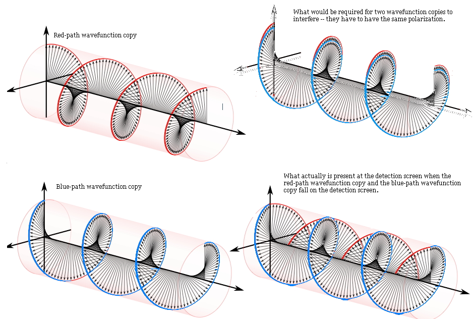
