This article's lead section may be too short to adequately summarize the key points. (February 2015) |
Oblique projection is a simple type of technical drawing of graphical projection used for producing two-dimensional (2D) images of three-dimensional (3D) objects.

The objects are not in perspective and so do not correspond to any view of an object that can be obtained in practice, but the technique yields somewhat convincing and useful results.
Oblique projection is commonly used in technical drawing. The cavalier projection was used by French military artists in the 18th century to depict fortifications.
Oblique projection was used almost universally by Chinese artists from the 1st or 2nd centuries to the 18th century, especially to depict rectilinear objects such as houses.[1]
Various graphical projection techniques can be used in computer graphics, including in Computer Aided Design (CAD), computer games, computer generated animations, and special effects used in movies.
Overview
edit


Oblique projection is a type of parallel projection:
- it projects an image by intersecting parallel rays (projectors)
- from the three-dimensional source object with the drawing surface (projection plane).
In both oblique projection and orthographic projection, parallel lines of the source object produce parallel lines in the projected image. The projectors in oblique projection intersect the projection plane at an oblique angle to produce the projected image, as opposed to the perpendicular angle used in orthographic projection.
Mathematically, the parallel projection of the point on the -plane gives . The constants and uniquely specify a parallel projection. When , the projection is said to be "orthographic" or "orthogonal". Otherwise, it is "oblique". The constants and are not necessarily less than 1, and as a consequence lengths measured on an oblique projection may be either larger or shorter than they were in space. In a general oblique projection, spheres of the space are projected as ellipses on the drawing plane, and not as circles as they would appear from an orthogonal projection.


Oblique drawing is also the crudest "3D" drawing method but the easiest to master. One way to draw using an oblique view is to draw the side of the object you are looking at in two dimensions, i.e. flat, and then draw the other sides at an angle of 45°, but instead of drawing the sides full size they are only drawn with half the depth creating 'forced depth' – adding an element of realism to the object. Even with this 'forced depth', oblique drawings look very unconvincing to the eye. For this reason oblique is rarely used by professional designers or engineers.
Oblique pictorial
editIn an oblique pictorial drawing, the angles displayed among the axis, as well as the foreshortening factors (scale) are arbitrary. More precisely, any given set of three coplanar segments originating from the same point may be construed as forming some oblique perspective of three sides of a cube. This result is known as Pohlke's theorem, from the German mathematician Pohlke, who published it in the early 19th century.[2]
The resulting distortions make the technique unsuitable for formal, working drawings. Nevertheless, the distortions are partially overcome by aligning one plane of the image parallel to the plane of projection. Doing so creates a true shape image of the chosen plane. This specific category of oblique projections, whereby lengths along the directions and are preserved, but lengths along direction are drawn at angle using a reduction factor is very much in use for industrial drawings.


Cavalier projection
editIn cavalier projection (sometimes cavalier perspective or high view point) a point of the object is represented by three coordinates, x, y and z. On the drawing, it is represented by only two coordinates, x″ and y″. On the flat drawing, two axes, x and z on the figure, are perpendicular and the length on these axes are drawn with a 1:1 scale; it is thus similar to the dimetric projections, although it is not an axonometric projection, as the third axis, here y, is drawn in diagonal, making an arbitrary angle with the x″ axis, usually 30 or 45°. The length of the third axis is not scaled.[5][6]
It is very easy to draw, especially with pen and paper. It is thus often used when a figure must be drawn by hand, e.g. on a black board (lesson, oral examination).
The representation was initially used for military fortifications. In French, the "cavalier" (literally rider, horseman, see Cavalry) is an artificial hill behind the walls that allows sighting of the enemy above the walls.[7] The cavalier perspective was the way the things were seen from this high point. Some also explain the name by the fact that it was the way a rider could see a small object on the ground from his horseback.[8]
Cabinet projection
editThe term cabinet projection stems from its use in illustrations by the furniture industry.[9] Like cavalier perspective, one face of the projected object is parallel to the viewing plane, and the third axis is projected as going off at an angle (typically atan(2) or about ~63.4°). Unlike cavalier projection, where the third axis keeps its length, with cabinet projection the length of the receding lines is cut in half.
Mathematical formula
editAs a formula, if the plane facing the viewer is xy, and the receding axis is z, then a point P is projected like this:

Where is the mentioned angle.

The transformation matrix is:

Alternatively one could remove one third from the leading arm projected off the starting face, thus giving the same result.
Military projection
editIn the military projection, the angles of the x and z-axis and y and z -axis are at 45°, meaning that the angle between the x-axis and the y-axis is 90°. That is, the xy-plane is not skewed. It is rotated over 45°, though.[10]
Examples
editBesides technical drawing and illustrations, video games (especially those preceding the advent of 3D games) also often use a form of oblique projection. Examples include SimCity, Ultima VII, Ultima Online, EarthBound, Paperboy and, more recently, Tibia.
-
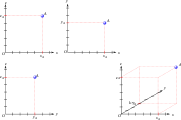
 The figures to the left are orthographic projections. The figure to the right is an oblique projection with an angle of 30° and a ratio of 1⁄2.
 -
 Potting bench drawn in cabinet projection with an angle of 45° and a ratio of 2/3.
 -
 Pieces of fortification in cavalier perspective (Cyclopaedia vol. 1, 1728).
 -
 How the coordinates are used to place a point on a cavalier perspective.
 -
 Stone arch drawn in military perspective.
 -
 Stone arch drawn in cabinet perspective.
 -
 A representative Korean painting depicting the two royal palaces, Changdeokgung and Changgyeonggung located in the east of the main palace, Gyeongbokgung.
 -
 Entrance and yard of a yamen. Detail of scroll about Suzhou by Xu Yang, ordered by the Qianlong Emperor. 18th century
 -
 18th century plan of Port-Royal-des-Champs drawn in military projection
 -
 A variation of military projection is used in the video game SimCity
 -
 A 3D rendered magnetic resonance angiography, shown in an oblique projection in order to distinguish the aberrant subclavian artery


See also
editReferences
edit- ^ Cucker, Felipe (2013). Manifold Mirrors: The Crossing Paths of the Arts and Mathematics. Cambridge University Press. pp. 269–278. ISBN 978-0-521-72876-8.
- ^ Weisstein, Eric W. "Pohlke's Theorem". From MathWorld—A Wolfram Web Resource.
- ^ a b Parallel Projections Archived 23 April 2007 at the Wayback Machine from PlaneView3D Online
- ^ Bolton, William (1995), Basic Engineering, Butterworth-Heinemann GNVQ Engineering Series, BH Newnes, p. 140, ISBN 9780750625845.
- ^ "Repair and Maintenance Manuals - Integrated Publishing". Archived from the original on 22 August 2010. Retrieved 22 August 2010. from "Repair and Maintenance Manuals - Integrated Publishing". Archived from the original on 22 August 2010. Retrieved 22 August 2010.
- ^ Ingrid Carlbom, Joseph Paciorek, Planar Geometric Projections and Viewing Transformations, ACM Computing Surveys, v.10 n.4, pp. 465–502, Dec. 1978
- ^ Etymologie des maths, letter C (French)
- ^ DES QUESTIONS D'ORIGINES (French)
- ^ Ching, Francis D. K.; Juroszek, Steven P. (2011), Design Drawing (2nd ed.), John Wiley & Sons, p. 205, ISBN 9781118007372.
- ^ "The Geometry of Perspective Drawing on the Computer". Retrieved 24 April 2015.
Further reading
edit- Foley, James (1997). Computer Graphics. Boston: Addison-Wesley. ISBN 0-201-84840-6.
- Ingrid Carlbom, Joseph Paciorek, Planar Geometric Projections and Viewing Transformations, ACM Computing Surveys, v.10 n.4, p. 465–502, Dec. 1978
- Alpha et al. 1988, Atlas of Oblique Maps, A Collection of Landform Portrayals of Selected Areas of the World (US Geological Survey)