
Original file (SVG file, nominally 957 × 724 pixels, file size: 32 KB)
| This is a file from the Wikimedia Commons. Information from its description page there is shown below. Commons is a freely licensed media file repository. You can help. |
Summary
| Description |
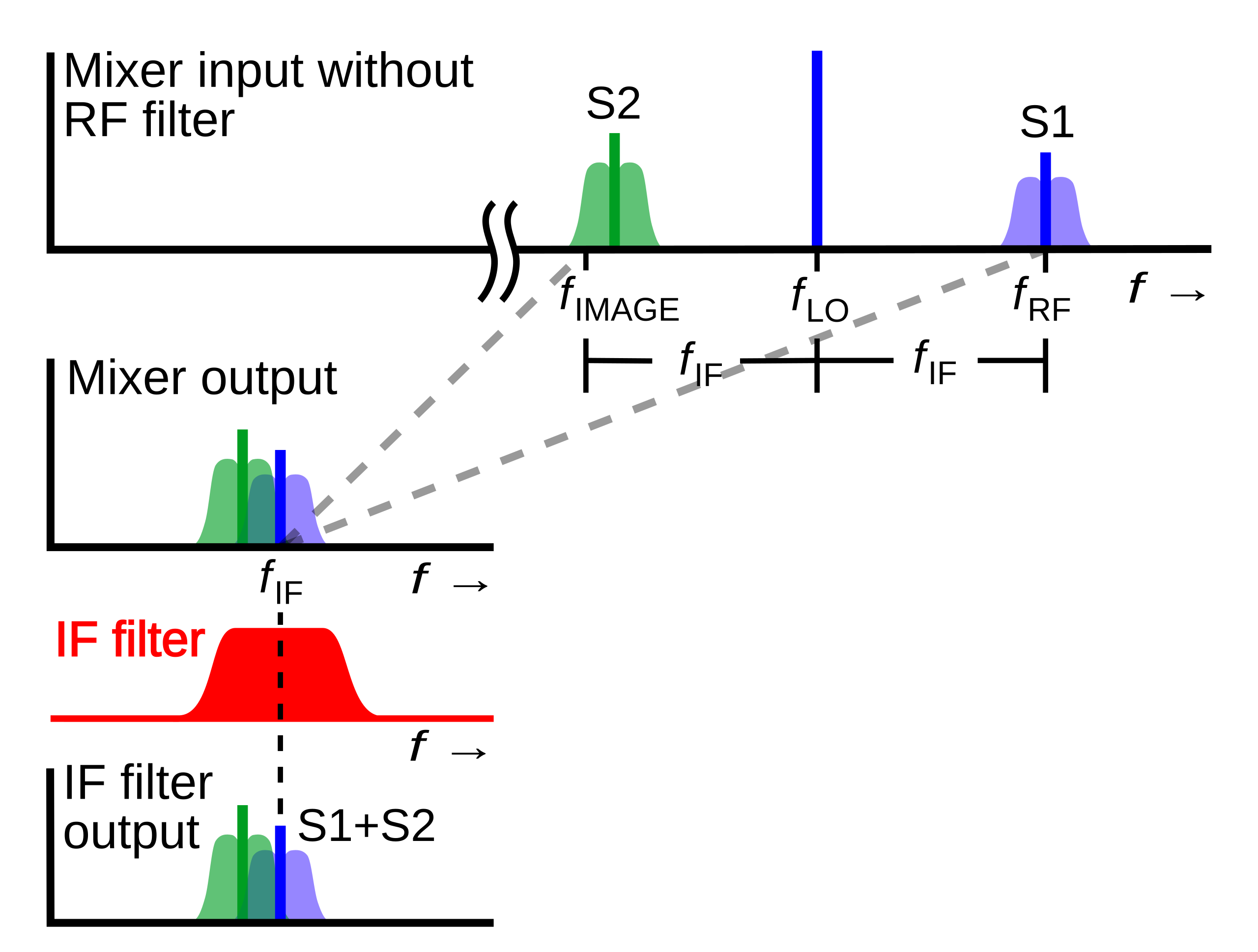
English: Diagram of the radio signals at different points in a superheterodyne radio receiver showing the problem of image response and why the receiver needs an RF image filter on the input. The horizontal axis is frequency while the vertical axis is voltage. The diagrams show what would happen in a superheterodyne without an RF filter.
In the superheterodyne the signal of the desired radio station (S1, blue) at frequency is mixed with a sinusoidal signal from a local oscillator (LO) at frequency , producing a heterodyne or "beat" frequency at the difference between the two frequencies, called the intermediate frequency (IF) at . After being shifted to the intermediate frequency, the signal S1 passes through the IF filter which removes signals at all other frequencies, and is demodulated. However there is a second frequency on the other side of the LO frequency which also produces a heterodyne at the IF frequency when mixed with the LO. This is called the image frequency . Thus the superheterodyne receives on two frequencies: Русский: Графики радиосигналов в разных точках супергетеродинного радиоприемника иллюстрирующие возникновение и прохождение по тракту помехи с зеркальной частотой и поясняющая почему приемнику обычно необходим входной радиочастотный фильтр. По горизонтальной осотложена частота сигналов, а вертикальная ось — напряжение, или на красном графике коэффициент передачи фильтра в зависимости от частоты. На диаграммах показано влияние помехи по зеркальному каналу в супергетеродине без входного фильтра. В супергетеродине сигнал нужной радиостанции (S1, синий) на частоте смешанный с синусоидальным сигналом от гетеродина на частоте , образуя биения с частотой равной разности частот сигнала и гетеродина, эта частота называется промежуточной частотой (ПЧ) в . После смешения в смесителе сигнал S1 проходит через фильтр ПЧ, который блокирует сигналы всех других частот и далее демодулируется. |
| Date | |
| Source | Own work |
| Author | Chetvorno |
| Other versions |
|
| SVG development | This diagram was created with Inkscape, or with something else. This diagram uses translateable embedded text. |


Licensing
| This file is made available under the Creative Commons CC0 1.0 Universal Public Domain Dedication. | |
| The person who associated a work with this deed has dedicated the work to the public domain by waiving all of their rights to the work worldwide under copyright law, including all related and neighboring rights, to the extent allowed by law. You can copy, modify, distribute and perform the work, even for commercial purposes, all without asking permission.
|
File history
Click on a date/time to view the file as it appeared at that time.
| Date/Time | Thumbnail | Dimensions | User | Comment | |
|---|---|---|---|---|---|
| current | 21:49, 7 April 2019 | | 957 × 724 (32 KB) | Chetvorno | Tweaked font size and placement of objects |
| 16:24, 9 May 2017 |  | 957 × 724 (28 KB) | Chetvorno | Fixed slight error in image and replaced invalid Inkscape SVG with "plain SVG" which passes validation | |
| 19:23, 8 May 2017 |  | 957 × 724 (29 KB) | Chetvorno | Fixed error in SVG that was causing appearance of black rectangular box | |
| 19:13, 8 May 2017 |  | 926 × 693 (39 KB) | Chetvorno | User created page with UploadWizard |
File usage
Global file usage
The following other wikis use this file:
- Usage on fa.wikipedia.org
- Usage on fr.wikipedia.org
- Usage on ja.wikipedia.org