In digital logic and computing, a counter is a device which stores (and sometimes displays) the number of times a particular event or process has occurred, often in relationship to a clock. The most common type is a sequential digital logic circuit with an input line called the clock and multiple output lines. The values on the output lines represent a number in the binary or BCD number system. Each pulse applied to the clock input increments or decrements the number in the counter.

A counter circuit is usually constructed of several flip-flops connected in a cascade. Counters are a very widely used component in digital circuits, and are manufactured as separate integrated circuits and also incorporated as parts of larger integrated circuits.
Electronic counters
editAn electronic counter is a sequential logic circuit that has a clock input signal and a group of output signals that represent an integer "counts" value. Upon each qualified clock edge, the circuit will increment (or decrement, depending on circuit design) the counts. When the counts have reached the end of the counting sequence (maximum counts when incrementing; zero counts when decrementing), the next clock will cause the counts to overflow or underflow, and the counting sequence will start over. Internally, counters use flip-flops to represent the current counts and to retain the counts between clocks. Depending on the type of counter, the output may be a direct representation of the counts (a binary number), or it may be encoded. Examples of the latter include ring counters and counters that output Gray codes.
Many counters provide additional input signals to facilitate dynamic control of the counting sequence, such as:
- Reset – sets counts to zero. Some IC manufacturers name it "clear" or "master reset (MR)".
- Enable – allows or inhibits counting.
- Direction – determines whether counts will increment or decrement.
- Data – parallel input data which represents a particular counts value.
- Load – copies parallel input data to the counts.
Some counters provide a Terminal Count output which indicates that the next clock will cause overflow or underflow. This is commonly used to implement counter cascading (combining two or more counters to create a single, larger counter) by connecting the Terminal Count output of one counter to the Enable input of the next counter.
The modulus of a counter is the number of states in its count sequence. The maximum possible modulus is determined by the number of flip-flops. For example, a four-bit counter can have a modulus of up to 16 (2^4).
Counters are generally classified as either synchronous or asynchronous. In synchronous counters, all flip-flops share a common clock and change state at the same time. In asynchronous counters, each flip-flop has a unique clock, and the flip-flop states change at different times.
Counters are categorized in various ways. For example:
- Modulus counter – counts through a particular number of states.
- Decade counter – modulus ten counter (counts through ten states).
- Up/down counter – counts up and down, as directed by a control input, or by the use of separate "up" and "down" clocks.
- Ring counter – formed by a "circular" shift register.
- Johnson counter – a twisted ring counter.
- Gray-code counter – outputs a sequence of Gray codes.
- Shift register generator counter – based on a shift register with feedback.
Counters are implemented in a variety of ways, including as dedicated MSI and LSI integrated circuits, as embedded counters within ASICs, as general-purpose counter and timer peripherals in microcontrollers, and as IP blocks in FPGAs.
Asynchronous (ripple) counter
edit
An asynchronous (ripple) counter is a "chain" of toggle (T) flip-flops wherein the least-significant flip-flop (bit 0) is clocked by an external signal (the counter input clock), and all other flip-flops are clocked by the output of the nearest, less significant flip-flop (e.g., bit 0 clocks the bit 1 flip-flop, bit 1 clocks the bit 2 flip-flop, etc.). The first flip-flop is clocked by rising edges; all other flip-flops in the chain are clocked by falling clock edges. Each flip-flop introduces a delay from clock edge to output toggle, thus causing the counter bits to change at different times and producing a ripple effect as the input clock propagates through the chain. When implemented with discrete flip-flops, ripple counters are commonly implemented with JK flip-flops, with each flip-flop configured to toggle when clocked (i.e., J and K are both connected to logic high).
In the simplest case, a one-bit counter consists of a single flip-flop. This counter will increment (by toggling its output) once per clock cycle and will count from zero to one before overflowing (starting over at zero). Each output state corresponds to two clock cycles; consequently, the flip-flop output frequency is exactly half the frequency of the input clock. If this output is then used as the clock signal for a second flip-flop, the pair of flip-flops will form a two-bit ripple counter with the following state sequence:
| Clock cycle | Q1 | Q0 | (Q1:Q0) decimal |
|---|---|---|---|
| 0 | 0 | 0 | 0 |
| 1 | 0 | 1 | 1 |
| 2 | 1 | 0 | 2 |
| 3 | 1 | 1 | 3 |
| 4 | 0 | 0 | 0 |
Additional flip-flops may be added to the chain to form counters of any arbitrary word size, with the output frequency of each bit equal to exactly half the frequency of the nearest, less significant bit.
Ripple counters exhibit unstable output states while the input clock propagates through the circuit. The duration of this instability (the output settling time) is proportional to the number of flip-flops. This makes ripple counters unsuitable for use in synchronous circuits that require the counter to have a fast output settling time. Also, it is often impractical to use ripple counter output bits as clocks for external circuits because the ripple effect causes timing skew between the bits. Ripple counters are commonly used as general-purpose counters and clock frequency dividers in applications where the instantaneous count and timing skew is unimportant.
Synchronous counter
edit
In a synchronous counter, the clock inputs of the flip-flops are connected, and the common clock simultaneously triggers all flip-flops. Consequently, all of the flip-flops change state at the same time (in parallel).
For example, the circuit shown to the right is an ascending (up-counting) four-bit synchronous counter implemented with JK flip-flops. Each bit of this counter is allowed to toggle when all of the less significant bits are at a logic high state. Upon clock rising edge, bit 1 toggles if bit 0 is logic high; bit 2 toggles if bits 0 and 1 are both high; bit 3 toggles if bits 2, 1, and 0 are all high.
Decade counter
edit
A decade counter counts in decimal digits, rather than binary. A decade counter may have each (that is, it may count in binary-coded decimal, as the 7490 integrated circuit did) or other binary encodings. A decade counter is a binary counter designed to count to 1001 (decimal 9). An ordinary four-stage counter can be easily modified to a decade counter by adding a NAND gate as in the schematic to the right. Notice that FF2 and FF4 provide the inputs to the NAND gate. The NAND gate outputs are connected to the CLR input of each of the FFs.".[1] It counts from 0 to 9 and then resets to zero. The counter output can be set to zero by pulsing the reset line low. The count then increments on each clock pulse until it reaches 1001 (decimal 9). When it increments to 1010 (decimal 10), both inputs of the NAND gate go high. The result is that the NAND output goes low, and resets the counter to zero. D going low can be a CARRY OUT signal, indicating that there has been a count of ten.
Ring counter
editA ring counter is a circular shift register that is initiated such that only one of its flip-flops is the state one while others are in their zero states.
A ring counter is a shift register (a cascade connection of flip-flops) with the output of the last one connected to the input of the first, that is, in a ring. Typically, a pattern consisting of a single bit is circulated, so the state repeats every n clock cycles if n flip-flops are used.
Johnson counter
editA Johnson counter (or switch-tail ring counter, twisted ring counter, walking ring counter, or Möbius counter) is a modified ring counter, where the output from the last stage is inverted and fed back as input to the first stage.[2][3][4] The register cycles through a sequence of bit-patterns, whose length is equal to twice the length of the shift register, continuing indefinitely. These counters find specialist applications similar to the decade counter (note: the 74x4017 decade counter is a Johnson counter), digital-to-analog conversion, etc. They can be implemented easily using D- or JK-type flip-flops.
Computer science counters
editIn computability theory, a counter is considered a type of memory. A counter stores a single natural number (initially zero) and can be arbitrarily long. A counter is usually considered in conjunction with a finite-state machine (FSM), which can perform the following operations on the counter:
- Check whether the counter is zero
- Increment the counter by one.
- Decrement the counter by one (if it's already zero, this leaves it unchanged).
The following machines are listed in order of power, with each one being strictly more powerful than the one below it:
- Deterministic or non-deterministic FSM plus two counters
- Non-deterministic FSM plus one stack
- Non-deterministic FSM plus one counter
- Deterministic FSM plus one counter
- Deterministic or non-deterministic FSM.
For the first and last, it doesn't matter whether the FSM is a deterministic finite automaton or a nondeterministic finite automaton. They have the same power. The first two and the last one are levels of the Chomsky hierarchy.
The first machine, an FSM plus two counters, is equivalent in power to a Turing machine. See the article on counter machines for a proof.
Web counter
editA web counter or hit counter is a computer program that indicates the number of visitors or hits a particular webpage has received. Once set up, these counters will be incremented by one every time the web page is accessed in a web browser.
The number is usually displayed as an inline digital image or in plain text or on a physical counter such as a mechanical counter. Images may be presented in a variety of fonts, or styles; the classic example is the wheels of an odometer.
Web counter was popular in the mid to late 1990s and early 2000s, later replaced by more detailed and complete web traffic measures.
Computer based counters
editMany automation systems use PC and laptops to monitor different parameters of machines and production data. Counters may count parameters such as the number of pieces produced, the production batch number, and measurements of the amounts of material used.
Mechanical counters
editLong before electronics became common, mechanical devices were used to count events. These are known as tally counters. They typically consist of a series of disks mounted on an axle, with the digits zero through nine marked on their edge. The right-most disk moves one increment with each event. Each disk except the left-most has a protrusion that moves the next disk to the left one increment after the completion of one revolution. Such counters were used as odometers for bicycles and cars and in tape recorders, fuel dispensers, in production machinery as well as in other machinery. One of the largest manufacturers was the Veeder-Root company, and their name was often used for this type of counter.[5]
Handheld tally counters are used mainly for stocktaking and counting people attending events.
Electromechanical counters were used to accumulate totals in tabulating machines that pioneered the data processing industry.
-
 Mechanical counter wheels showing both sides. The bump on the wheel displayed at the top engages the ratchet on the wheel below every turn.
 -
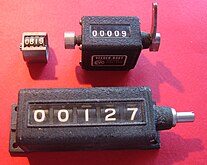 Several mechanical counters.
 -
 Early IBM tabulating machine using mechanical counters.
.jpg)


See also
editReferences
edit- ^ "Decade Counter". Integrated Publishing. Retrieved 19 Mar 2020.
- ^ Singh, Arun Kumar (2006). Digital Principles Foundation of Circuit Design and Application. New Age Publishers. ISBN 81-224-1759-0.
- ^ Horowitz, Paul; Hill, Winfield (1989). The Art of Electronics. Cambridge University Press. ISBN 0-521-37095-7.
- ^ Graf, Rudolf F (1999). Modern Dictionary of Electronics. Newnes. ISBN 0-7506-9866-7.
- ^ VR History, Veeder.
External links
edit Media related to Counter circuits at Wikimedia Commons
- Assim, Ara Abdulsatar Assim (2021-10-19). Design and Synthesis of a MOD 13 Binary Down Counter (Report). doi:10.36227/techrxiv.16810198.v1.