Jeffareid
Leave a message by clicking here.
Don't forget to sign your message with ~~~~.
Or leave an email: email:Jeffareid
RE: Bernoulli's principle and lift edit
Hi Jeff. Thanks for putting together your ideas and questions on this topic and asking for my thoughts. Your questions are good ones, and ones that many people have puzzled over before.
I have started thinking about your questions. I expect to have some thoughtful answers in a day or two. I will probably post my answers on my User talk page, adjacent to your questions. Cheers Dolphin51 (talk) 04:15, 21 June 2008 (UTC)
- Thanks, it's all been a bit confusing with the various "opinions" offered by what appear to be experts in the field. Jeffareid (talk) 07:09, 22 June 2008 (UTC)
Hi Jeff. I have now finished my responses to your questions. You will find them on my User talk page. If you have any further questions don't hesitate to fire them at me. Cheers. Dolphin51 (talk) 04:20, 27 June 2008 (UTC)
- Hi Jeff. You left some questions on my User talk page on 16 August. I have now responded with my ideas on the subject. See my User talk page. Apologies for the delay. Dolphin51 (talk) 03:14, 30 August 2008 (UTC)
Hi Jeffareid. It may provoke strong reactions on WP if you edit (or reformat) your own or others comments on an article's talk page, after other people have reacted. See WP:REDACT and WP:TALK#Editing_comments. Personally, in your case it is OK with me (and it also appears to be with Dolphin51), since you seem to to do this in good faith and try to make thinks clearer. But that may not be the case with everybody, so be aware of that. Also, a talk page is just a work place to assist editing the article itself. So it is less important to have things written there very neatly. Cheers, Crowsnest (talk) 21:33, 9 September 2008 (UTC)
- Hi Jeff. I read your comments to Michael Belisle on his Talkpage on 17 October. I'm not surprised you are feeling uncertain about how to explain Lift (force) if you are focussing on the book Understanding Flight by David Anderson and Scott Eberhardt. You described Anderson as an apparent expert - Anderson is certainly not an expert on aerodynamics. Anderson's and Eberhardt's book is only valid if it is a simple introductory book for student pilots and aviation beginners. In their book they are searching for a simple, easy way to explain flight so that beginners will have the best chance of comprehending it. They dismiss Bernoulli in favour of the alternative Newtonian approach. There is nothing wrong with Newton's approach, but it is incorrect to suggest that 'because Newton is right, Bernoulli must be wrong'. I wrote a critique of Understanding Flight which can now be seen at Talk:Bernoulli's principle/Archive 2#Understanding flight. Understanding Flight is a book for beginners for whom Bernoulli's principle is too complex. I'm pleased to observe that the Wikipedia articles Bernoulli's principle and Lift are superior to the pretentious writings of Anderson and Eberhardt. Best regards. Dolphin51 (talk) 01:40, 20 October 2008 (UTC)
Talk page archive edit
Hi Jeffareid. I archived the talk page of Bernoulli's principle because it was getting long (85 kilobyte). I don't intent to archive again (but I do not know what others will do) until it gets long again. Best regards, -- Crowsnest (talk) 20:05, 22 September 2008 (UTC)
trail and self stability edit
Either I missed it in the article, or the article left out the key factor in self stability, which is trail. This is easily demonstrated on bicycles where the front wheel can be turned backwards; by turning the front wheel backwards (assuming forward offset forks, the trail is increased a lot and the bicycle will almost come to a complete stop before falling over. Jeffareid (talk) 01:55, 18 October 2008 (UTC)
- Perhaps the existing text inadvertantly emphasizes the influence of gyroscopic effects on self-stability, simply due to the order of the sections. While I don't doubt the experiment you cite, first we would need a published source for it not to be OR; and second, it only suggests that increasing trail lowers the lower bound of the stable range. It doesn't indicate that trail is necessary nor sufficient for self-stability. -AndrewDressel (talk) 14:10, 18 October 2008 (UTC)
On a side note, too little trail is one source of speed wobble. This was an issue for the first year production of Honda's 900 RR motorcycle, where speed wobble was an issue when these motorcycles were raced. In the second and later years, the forks were adjusted 3/8" back to increase the trail and eliminate the speed wobble issue. Jeffareid (talk) 01:55, 18 October 2008 (UTC)
- All Cossalter says is that "wobble frequency goes up as trial increases and front-frame inertia decreases". He continues with "[it] is determined mainly by the stiffness and damping of the front tire, although the lateral flexibility of the front fork also plays a part." Can anyone verify that the amount of trail was the only change that Honda made? -AndrewDressel (talk) 14:10, 18 October 2008 (UTC)
- It wasn't the only change, and Honda made the change much later than I thought. The issue created an aftermarket for triple clamps with more trail (less offset), and is mentioned in this Wiki reference to the 1998 model: 5 mm (0.20 in) less triple clamp offset (an almost universal aftermarket upgrade to previous models). Jeffareid (talk) 01:47, 20 October 2008 (UTC)
You are raising excellent points about the article. Thanks for taking a look at it. -AndrewDressel (talk) 14:10, 18 October 2008 (UTC)
Bicycle_and_motorcycle_dynamics: talk page: trail and self stability edit
Perhaps you could help out here when you get the time?
Regarding bicycles (or motocycles) I've alway's thought that main source of self stability was fork trail. I've read this in numerous articles, that included the results of actual testing of real bicycles where the trail was varied from negative (no stability) to very positive (lots of stability). However, Andrew Dressel appears to be disputing a relationship between trail snd self stability.
- In all the excitement, you might have missed that I actually am Andrew Dressel. -AndrewDressel (talk) 19:50, 18 October 2008 (UTC)
I've added the following section to the talk page:
I'm also confused about the capsize speed, since I've never experienced this. The eigenvalues section includes a diagram showing that some model of a bicycle will go unstable at around 18mph. However this speed seems slow. A winning racing bicyclist often goes hand free at the end of a race, well over 30mph, with no apparent instability. Motorcycle races sometimes fall off their bikes at high speeds, and the bikes continue on with no apparenty instability.
Jeffareid (talk) 19:20, 18 October 2008 (UTC)
- The particular eigenvalues plotted are for a utility bicycle, not a race bike nor a motorcycle.
- A rider sitting up on his bike with his hands in the air is completely different from a riderless bike. Riding no-hands is not a demonstration of self-stability.
- As the article already states: a capsize can happen very slowly if the bike is moving forward rapidly. Because the capsize instability is so slow, on the order of seconds, it is easy for the rider to control, and is actually used by the rider to initiate the lean necessary for a turn. -AndrewDressel (talk) 19:50, 18 October 2008 (UTC)
I've experienced turning a motorcycle at 100mph (not all out, but at about 80% of maximum grip), and the main difference is that the bike tends to hold it's lean angle (lean stability) as opposed to straightening up (vertical stability), when I wasn't applying any torque to the handle bars. I had to use the same amount of inwards counter steering to straighten up as outwards counter steering to lean over. It was similar to flying a plane with no dihedral effects, once banked, it just held the bank angle (the motorcycle at 100mph). At slower speeds, the motorcycle tends to straighten up and requires a constant amount of outwards counter-steering torque in order to hold a lean angle.
- It sounds as though you are experiencing the different behaviours on either side of the so-call inversion speed. As the article already states: at speeds below the capsize speed, also called the inversion speed, the self-stability of the bike will cause it to tend to steer into the turn, righting itself and exiting the turn, unless a torque is applied in the opposite direction of the turn. At speeds above the capsize speed, the capsize instability will cause it to tend to steer out of the turn, increasing the lean, unless a torque is applied in the direction of the turn. At the capsize speed no input steering torque is necessary to maintain the steady-state turn. -AndrewDressel (talk) 19:50, 18 October 2008 (UTC)
I've always thought that the tendency to straighten up is due to the inwards yaw torque on the steering due to fork trail effect. Regarding the transition into lean stability at high speeds, I've always though that it was due to gyroscopic effets.
Jeffareid (talk) 19:33, 18 October 2008 (UTC)
- I've read about the same neutral handling (no steering required to hold a lean angle) effect not having a known upper limit in articles about motocycle racing. It starts at around 100mph, and continues to feel the same up to the 200mph or so speeds that racing motorcycles reach. Most racing tracks don't have turns at this speed. Daytona has a 180+mph turn, but it's steeply banked. The main exception is the Ilse of Mann (it's a timed event verus a true race), where there are several 150mph to 200mph turns. The racers claim that 200mph turns feel no different than 100mph turns, no steering inputs are required to maintain a lean angle, stereing input are only used to change the lean angle. However the faster you go, the more counter steering force it takes to change the lean angle, and the force is quite large at high speeds. At slower speeds, 80mph or less, some amount of constant counter steering and/or hanging off the motorcycle is required to maintain lean angles to prevent the motorcycle from reducing the lean angle (returning to vertical). The reason stated for neutral handling at high speeds was gyroscopic effects, which resist any change in the roll axis. Yaw torque due to trail on the front wheel should result in some outwards roll precession, but the rate is very small and resisted by the rear tire which is larger and has more momentum. The reason usually given for vertical stability at lower speeds is fork trail. Jeffareid (talk) 20:51, 18 October 2008 (UTC)
- There is a ton of conventional wisdom and lore out there, perhaps largely because the correct equations have been so hard to pin down and so opaque to conventional dynamic analysis. I have yet to see a convincing treatment that teases out what parameter is responsible for what behavior at what speed. That may not even be possible. Another part of the problem could be that there are so many parameters at play. I'm afraid the best we can do in this article at this point is point out that parameters that do contribute.
- It may be true that racing motorcycles do not have a capsize speed, but I have not seen physical test data, and the one eigenvalue plot for motorcycles I have seen, by Cossalter, which does appear to have a finite capsize speed does not indicate how complete the model is. Perhaps it doesn't include tire effects, and they increase the capsize speed on real bikes. -AndrewDressel (talk) 22:19, 18 October 2008 (UTC)
- I found some videos testing stability on a treadmill from the Delft bicycle research page. The fastest test is at 30km/h = 18.64 mph, or 8.33 m/sec, (slightly above the stated capsize speed), the bike is very stable. treadmill measurements. Jeffareid (talk) 23:16, 18 October 2008 (UTC)
- Since that page you link to doesn't state a capsize speed, I'm guessing you are refering to the capsize speed stated in this wikipedia article. That value is merely an example calculated for one particular idealized bicycle. I've added some words that I hope make it clearer that the plot of eigenvalues is for one particular bike. -AndrewDressel (talk) 14:28, 19 October 2008 (UTC)
- The capsize speed is shown in a graph on another article from Delft, and it appears to be the same bicycle: Koo06.pdf
- The graphs shows capsize speed at below 8m/s, but the tread mill runs shows and states that the bicycle is very stable at 30km/s == 8.64 m /s. I'm waiting for feedback from someone at Delft, but my guess is that tire width is an issue. When leaned over, the contact patch is on the side of the tire, and this offset creates an outwards torque on the roll axis. Tire width and a rear tire much larger than the front tire may explain why the capsize "rate" is imperceptible on motorcycles at high speed. Jeffareid (talk) 23:09, 19 October 2008 (UTC)
slip angle edit
- slip angle links (plenty of these at various web sites)
- Not much for references. One of the three links appears to be broken. -AndrewDressel (talk) 01:29, 21 October 2008 (UTC)
- I'm leery of these guys. They also claim that the rear wheel and engine provide significant stabilization via gyroscopic forces (The third gyroscope), and they provide no credible source for such claims. -AndrewDressel (talk) 01:29, 21 October 2008 (UTC)
- camber thrust (again plenty links on this):
Article explaining camber thrust: tyres
- While I don't dispute the final results, I don't like the argument used to develop it. They completely ignore the fact that bikes and cars have front and rear tires and the center of curvature is at the intersection of their axes. -AndrewDressel (talk) 01:29, 21 October 2008 (UTC)
Tiny graph in this link: motorcycle tire information
- Seems to agree with Cossalter: camber thrust generates more than enough centripetal force for cornering up to about 30 degrees. Below that, there will actually be negative side slip. Above that, side slip increases rapidly. -AndrewDressel (talk) 01:29, 21 October 2008 (UTC)
Experiment disputing camber thrust: wheels that don't turn Scroll down web page for this link. It's currently broke though. A description of the experiment: Terry made a rig that consisted of two paper cups and a frame. The axles of the paper cups were parallel to each other. Even though the "outer" diameters of the paper cups were larger than the "inner" diameters, the rig rolled in a straight line.
- Ignores the fact that camber thrust is caused by deforming the tire carcass, not simply by the conical shape. -AndrewDressel (talk) 01:29, 21 October 2008 (UTC)
- my thought - camber torque versus camber thrust versus slip angle
A cone segment shaped tire turns in a circle because it's contact patch generates an inwards yaw torque as the tire rolls forwards, which causes the tire to turn (yaw) over time and travel in a circular path. The contact patch deforms in normal slip angle mode. As speed increases, the radius will become larger because the slip angle increases with centripetal force, which increases relative to speed^2. The point here is that the cone aspect of the tire creates a (yawing) torque, not a (centripetal) force.
- Tires with non-zero camber angle can generate a yawing torque, a centripetal force, or some combination of the two. -AndrewDressel (talk) 01:29, 21 October 2008 (UTC)
Now expand this to a vehicle with two cone segment shaped tires. The inwards yaw torque from the rear tire produces an inwards force on the front tire. The inwards yaw torque from the front tire is more complicated because the front wheel can yaw (steer). It would produce an outwards force on the rear tire if the steering angle was fixed or resisted by a rider. The net difference in these forces, could be considered camber thrust. These camber related forces would be added to the centripetal related forces on the tires, eventually ending up as conventional slip angle related deformations. Note that the inwards yaw camber torque at the front tire causes it to steer inwards, and this may be factor in capsize speed in the case of a riderless bicycle. Camber torque must be relatively small, because it doesn't prevent a riderless bicycle from being stable within reasonable speed range, and it doesn't exhibit itself as a significant torque felt at the handlebars by a rider.
- Wilson and Papadopoulos, citing Cossalter, agree that tire "scrub" torque may be responsible for suppression of the capsize instability at high speed. -AndrewDressel (talk) 01:29, 21 October 2008 (UTC)
If the two cone shaped tire vehicle had parallel axis, then I'm not sure what happens. Terry Colon did an experiment using paper cups, but the friction was low allowing slippage, and it's possible that the straight line was really a circle with a very large radius. Note that the yawing torque from each tire is resisted by a sideways force by the other tire, so I don't know if there is any net torque or force on the overall vehicle. I wonder what would happen if only one of the tires was cone like and the other was flat?
Jeffareid (talk) 21:02, 20 October 2008 (UTC)
I can find several examples of authors that claim that side slip causes centripetal force, instead of merely being a symptom of centripetal force. The best treatment I know of online is at http://www.dinamoto.it/ -AndrewDressel (talk) 01:29, 21 October 2008 (UTC)
- In compliance with Newtons 3rd law, and rather than specify cause and effect, I was just trying to state that slip angle deformation coexists with centripetal force. It's my belief that the conical aspect so often referred to as camber thrust is actually a torque and not a linear force. I get the feeling that some of these articles are using the term camber thrust to include factors other than the difference in diameters of the inner and outer sufaces of a contact patch. Then again, perhaps I've generalized the term slip angle too much to include any deformation that results in the effective radius of a turn being larger than the no-load radius of a turn. Jeffareid (talk) 04:03, 21 October 2008 (UTC)
- Regarding camber thrust, if a single tire is rolling along a banked track, does it turn uphill? Jeffareid (talk) 04:03, 21 October 2008 (UTC)
- Note, I've been double posting on both my talk page and yours to keep them in sync. Is there an alternative method? For example, update one of the discussion sections on one talk page, then go to the other, delete the contents of that discussion section and paste in the update? Jeffareid (talk) 04:10, 21 October 2008 (UTC)
- No. I don't know of a better solution. -AndrewDressel (talk) 19:02, 24 October 2008 (UTC)
- It's been a while with no response. Any new ideas or comments?
- Sorry. The conversation seems to have gotten bogged down in need of details we don't have, and school is getting busy. -AndrewDressel (talk) 19:02, 24 October 2008 (UTC)
Bernoulli demonstration with drinking straw edit
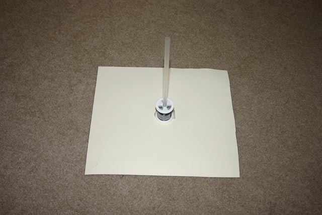
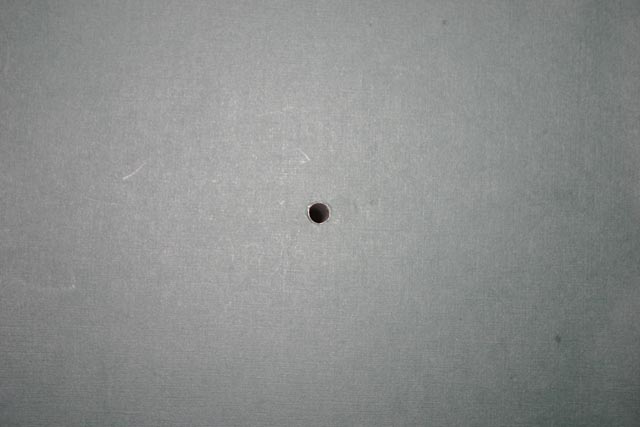
I've found several examples of Bernoulli princicple being "demonstrated" by having a stream of air blow across the top of straw with the other end drawing up water from glass implying that the pressure in the stream of air is below ambient.
Realizing that aircraft use static ports to sense the pressure of moving air, I decided to create my own static port using by inserting the end of the straw through a spool of thread and attaching it to a piece of carboard. Links to pictures of my "static port":
If the breeze is strong, then you'd want to cut down the size of the cardboard, or use wood. However at this point, note that real static ports can be purchased for less than $20 (USA):
I then repeated the pressure measurement test using a blow dryer and a straw in water. With just the straw, the water rises indicating lower pressure in the straw. With the static port there was virtually no movment of the water.
I then noted a surface tension and friction effect was resisting vertical movement within the straw, so I mixed in a small amount of liquid soap into the water. This changed the surface within the straw from convex to concave, and for some reason raised the water a slight amount (capillary like effect?). Retesting with the "static port" the water receded a small amount, indicating a slighly higher than ambient pressure in the output stream of the blow dryer.
The blow dryer source is also problematic, because it has a tapered nozzle, acting as a venturi to cause a Bernoulli type exchange of speed for pressure.
If the nozzle wasn't tapered, then the wash from the fan would have higher than ambient pressure, unless there is some special design of fan or propeller that reduces pressure fore of the prop more than than it increases pressure across the prop disc. This Nasa link explains what I'm getting at (prop increases pressure, air continues to accelerate after the prop as it's pressure returns to ambient):
I'm not sure what is going on with the exposed end of the straw in a stream other than it interferes with the stream while the static port doesn't (apparently it's "hiding" in the boundary layer of air near the surface around the port). It's how the exposed end of the straw inteferes with the stream that has me puzzled, does it generate a vortice with corresponding low pressure? Jeffareid (talk) 04:11, 26 January 2009 (UTC)
- Hi Jeff. I will be very interested to look at your web sites in the next day or two. The experiment with the drinking straw is an interesting one. If you blow a plume of air close to the straw, but far enough away so that the end of the straw doesn't interfere with the plume, you will find the water is not drawn upwards, indicating the pressure in the straw is not affected. But if you blow the plume at the end of the straw so that the straw interferes with the plume, the plume must flow around the end of the straw. In curving around the top of the straw the plume of air follows a path that represents a segment of a vortex. (With any vortex, pressure decreases towards the center of rotation, and where the pressure is lowest velocity must be highest, in accordance with Bernoulli's principle.) The outside of the vortex is exposed to the atmosphere so the air at the outside is at atmospheric pressure. The inside of the vortex is only exposed to the interior of the straw and its pressure is lower than atmospheric because its speed is faster than the outside of the vortex.
- A similar phenomenon can be seen on a much, much larger scale, with the tropical cyclone. Towards the center of the cyclone the air speed increases progressively and the pressure falls progressively, in accordance with Bernoulli's principle. A tropical cyclone is an atmospheric vortex on a giant scale. Dolphin51 (talk) 11:28, 26 January 2009 (UTC)
- I thought it might be related to vortex generation, but I wasn't sure. I will be very interested to look at your web sites in the next day or two. - My links are just to two pictures (1 jpeg image per link). The prop analysis site is a single NASA educational web page, with fairly simple explanation of prop wash. My issue is that I've seen "vertical straw (or tube) in a horizontal flow" used at a lot of web sites explaining Bernoulli, implying it was the horizontal speed, and not the vortex (or vortex like) interaction with the straw. Do a web search for "bernoulli water straw" and you get a lot of hit's about Bernoulli atomizer. Jeffareid (talk) 14:18, 26 January 2009 (UTC)
- Thanks for the photographs, and the link to the two web sites. The standard static ports regularly used on aircraft are flush with the surface of the fuselage. If the static port consisted of a hollow tube, perpendicular to the surface of the fuselage, ending about 1 inch (2.54 cm) above the surface it would make an interesting experiment. This arrangement would set up a segment of an elementary vortex over the end of the hollow tube, and lead to a pressure in the static system that is lower than the pressure of the freestream. I think the altimeter would over-read the altitude of the aircraft; and over-read the indicated airspeed. Dolphin51 (talk) 01:57, 27 January 2009 (UTC)
Lift (force) edit
Hi Jeff. On 1 March 2009 you made the following entry in response to one of mine, both at Talk:Lift (force)#Upwash:
causing the particle to finish where it started. - This conflicts with the fact that the particles that the wing passes under end up displaced from the particles that the wing passes over.
I agree with you. When I wrote my comment about particles finishing where they started I was obviously thinking about a sphere (or a cylinder). Non-rotating spheres and cylinders don't generate lift so particles finish where they started. The same is true with an airfoil generating zero lift. When an airfoil is generating lift there is cleavage of the flow and, as described by the Kutta condition, the flow over the top of the airfoil moves very fast and never returns to its starting position. (Maybe the flow under the lower surface of the airfoil moves a little too slow and also never returns to its starting position. I need to think about that one.)
I have noticed that a number of contributors to Talk:Lift (force), including you, are inclined to add a new comment right in the middle of some other User's text. (Your comment on 1 March, described in the para above, is an example.) As a result it becomes almost impossible for readers to determine who wrote what because part of each User's text becomes separated from his signature block. I would appreciate it if you always add your comments immediately after someone else's signature block, rather than in the middle of someone else's text. Many thanks! Best regards. Dolphin51 (talk) 23:51, 17 March 2009 (UTC)
Upwash edit
Hi Jeffareid. I archived the talk page of "Lift (force)", because of its length (137 kB). Unfortunately that also moved your contribution of April 7 to the Upwash section there. I will try to create the streamline plot you requested (but cannot promise whether I will succeed and when). Shall we discuss here? Or create an "Upwash (cont'd)" section at the talk page of "Lift (force)", at the moment that may be needed? Further, the WikiProject "Fluid dynamics" has been revived as a task force, see WP:FDTF. If you like to join in, you can do so there. Best regards, Crowsnest (talk) 18:19, 10 April 2009 (UTC)


Flow velocity vectors in a frame of reference moving with the airfoil Flow velocity vectors in a frame of reference moving with the oncoming air 

Streamlines in a frame of reference moving with the airfoil Streamlines in a frame of reference moving with the oncoming air


- Hello Jeffareid. These are the streamline plots in the two different frames of reference. Note that in the frame of reference moving with the oncoming air (say for an observer fixed to the ground in case of stagnant air/no wind), the airfoil moves from the right to the left. This means that the streamlines in this time-dependent flow are not equal to pathlines or streaklines (while they are for the reference frame moving with the airfoil, an observer in the airplane). -- Crowsnest (talk) 00:11, 13 April 2009 (UTC)

(unindent) Why do you expect the streamlines to become vertical lines far from the airfoil? Comment: also note the streamline spacing increases with distance to the airfoil, so the velocities and other effects reduce with distance from the airfoil. The airfoil only significantly disturbs the fluid in its neighbourhood. -- Crowsnest (talk) 09:48, 14 April 2009 (UTC)
- Someone posted a link to a website with airflow diagrams that correspond to what I've seen before, which explains my expectations. [avweb_wings.htm] Jeffareid (talk) 00:27, 29 April 2009 (UTC)
I like the other one and animation, since they show the displacement of the air by the passage of the airfoil (Darwin drift). The schematic one is a bit too "schematic", in my opinion, see the velocity vectors in the top-right picture above. -- Crowsnest (talk) 15:49, 29 April 2009 (UTC)
- The issue I'm having here is your vector diagram differs from one I saw years ago. In the diagram I recall, the upwash was localized to the immediate area near where the wing passed through diminishing with vertical distance, eventually becoming downwards sufficiently far away from the airfoil. Downwards and backwards above and in front of the airfoil, downwards and forwards (a slight amount, drag), behind the airfoil, but mostly downwards except near the localized upwash at the front of the wing. Any chance your vector diagram is based on potential flow theory as opposed to real air? Jeffareid (talk) 11:47, 30 April 2009 (UTC)
- Vector plots are a bit tricky, with respect to the size of the vectors being used. I will play a bit with it, enlarge the vectors, and see whether I can reproduce it more according to your expectations. I do not think it has to do with potential theory or real air, but has to do with how to represent the results. -- Crowsnest (talk) 12:31, 30 April 2009 (UTC)

- Hi, Jeff. It may help to understand the seeming discrepancy to think of the air-based streamline plot slightly differently. Pick any point on the plot (above wing would be good). Now picture the streamline plot at a later time, when the wing has disappeared far to the left. To know what it will look like, mentally "scroll" the above plot. What do you see? Exactly what you expected: roughly vertical, roughly straight lines, pointed left a little if friction is taken into account. What is the direction at the point you chose? Down and a little to the left, just as you expected. If the direction is still too much rightward and too curved, just let more time lapse ("scroll" farther). The streamline at that point will get straighter and straighter, and closer and closer to the direction you expected.
- Does this help? Admittedly, the instantaneous direction at the top of the initial plot when the wing is just now passing through isn't what you expected, (the other diagrams you recall must be in error, I suppose, if they imply that) but to see the ultimate effect of the wing on the air, you need to look at an air-based streamline plot of a point far behind the current location of the wing.
- Mark.camp (talk) 14:37, 11 January 2011 (UTC)
Response to your questions/comments elsewhere edit
Hi Jeff,
I responded in two places to comments/questions you posed at the following location:
http://en.wikipedia.org/wiki/Talk:Bernoulli%27s_principle
Today is my first day ever to post on wikipedia, so I'm not sure how to include the pointers to the comments or if it's even necessary. I know I can put something inside pairs of square brackets, but not sure what should go in there. Anyway, I suppose you will sort it out.
-Kim
Kimaaron (talk) 06:22, 9 September 2009 (UTC)

You can remove this notice at any time by removing the {{Talkback}} or {{Tb}} template.