This article has multiple issues. Please help improve it or discuss these issues on the talk page. (Learn how and when to remove these template messages)
|
Buffers and chain couplers (also known as "buffers and screw", "screw", and "screwlink") are the de facto International Union of Railways (UIC) standard railway coupling used in the EU and UK, and on some railways in other parts of the world, such as in South America and India, on older rolling stock. Buffers and chain couplers are an assembly of several devices: buffers,[1] hooks and links, or turnbuckle screws.[2]
On the modern version of the couplers, rail vehicles are mated by manually connecting the end link of one chain which incorporates a turnbuckle screw into the towing hook of the other wagon, drawing together and slightly compressing the buffer pairs, one left and one right on each headstock. That limits slack, and lessens shunting shocks in moving trains. By contrast, vehicles fitted with the semi-automatic Janney Type E coupler can experience significant jarring during mating and shunting. Very early rolling stock had "dummy buffers", which were simple rigid extensions of the frame, but they were improved with the use of enclosed mechanical, then hydraulic, springs to damp possible jarring. Each chain incorporates both a hook and a turnbuckle.
Variants edit
Three-link couplings edit

A peculiarly British practice was the "loose-coupled" freight train, operated by the locomotive crew and a "guard" at the rear of the train, the successor to the brakesman of earlier times. That train type used three-link chain couplings for traction and side buffers to accept pushing forces but, since such trains were not fitted with an automatic through-train braking system, there were no pipes to connect between the vehicles. The last vehicle of the train was a heavily ballasted guard's van with its brakes controllable by a handwheel operated by the guard. The slack between vehicles was very convenient when starting heavy trains with a relatively low-powered locomotive on the level or on a rising gradient.
On the driver's command the guard would apply his brake as hard as possible. The driver would then gently reverse to close up the wagons onto their buffers. Then the locomotive was driven ahead, picking up the load wagon by wagon, thus giving an easy start up the gradient. Wagons of that era didn't have roller bearings and the grease-lubricated plain bearings exerted considerable resistance, especially on a cold day, so starting wagon-by-wagon greatly reduced the traction force required from the locomotive.
The disadvantage of that convenience was that the guard could get badly thrown about as the train changed speed due to the inter-wagon gaps opening or closing. In the worst case, the jerks could break a coupling or cause a derailment. A skilled guard would observe or listen to his train and apply or release his brake to keep the last few couplings reasonably taut, acting as a shock-absorber. The same effect occurred when the route changed gradient. When going over a hill the rear of the train would catch up with the wagons held back by the locomotive, but the guard could minimise that. That method of train working was why the guard, just like the driver, was required to prove his route knowledge before being given charge of a heavy train. Loose-coupled trains travelled at low speeds and were phased out in the 1970s.[3]
An improvement on the loose-coupled train is the "Instanter" coupling, in which the middle link of a three-link chain is specially triangular shaped, so that when lying "prone" it provides enough slack to make coupling possible, but when the middle link is rotated 90 degrees, the length of the chain is effectively shortened, reducing the amount of slack without the need to wind a screw. The closeness of the coupling allows the use of inter-vehicle pipes for train brakes. Three-link and Instanter couplings can be operated entirely from the side of the wagons, using a shunter's pole, which has a hook on the end, and is safer when shunting is being done. Similarly, the screw-adjustable coupler can be connected by a shunter's pole once it has been unscrewed. Ordinary three-link couplings have been superseded by instanter, screw or buck-eye couplers in UK freight trains today.
Center-buffer-and-chain(s) edit

On some narrow-gauge lines in Europe, and on the Paris Metro, a simplified version of the loose-coupler is used, consisting of a single central buffer with a chain underneath. Sometimes there are two chains, one on each side of the coupler. The chain usually contains a screw-adjustable link to allow close coupling. These variants are also used elsewhere. On sharp curves, a single centre buffer is less likely to be subject to buffer-locking. The Eritrean Railway also uses a centre buffer and chain coupler.
Problems with buffers and chain edit
Buffer-locking edit

On sharp reverse curves, the buffers can become locked by slipping over and onto the back of each other. Although careful track design makes this a rare occurrence, a series of derailments at Stuttgart Central Station in 2012 were caused by buffer-locked wagons. Buffer-lock could occur on very sharp switches on rolling stock with the older, rounded buffers. Newer buffers are rectangular and are wider than they are tall. Buffers and chain couplers allow curves to have around 150 m (492 ft) radius, but sharp S-curves are not allowed. If it weren't for the couplers, much sharper curves could be allowed, on the condition the train is not too long.[4]
Variation with gauge edit
The width between the buffers tends to increase as the track gauge increases and decrease as the track gauge decreases, which means that if wagons are changed from one gauge to another, the buffers might no longer match. That is because the buffers are originally extensions of the frames, which are spaced according to the gauge of the track. As well, the height of the buffers is usually lower on narrow gauge railways, corresponding to the generally lower height of the rolling stock. Therefore, narrow gauge railways often use centre couplers without buffers.
However, in the case of Iberian broad gauge railways, the height and spacing of the buffers are the same as for standard gauge railways in Europe including Great Britain, in order to allow through-running of rolling stock by the use of bogie exchange.
Dimensions edit
Buffers and chain couplers tend to have the two buffers spaced according to the gauge, but especially in Europe this is modified to the standard gauge value to allow interrunning by means of bogie exchange.
Dimensions showing variation of spacing by gauge:
| Name | Gauge | Height | Separation | Region |
|---|---|---|---|---|
| Standard gauge | 1,435 mm (4 ft 8+1⁄2 in) | 1,054 mm (41.5 in) | 1,727 mm (68.0 in)[5] | Great Britain, European mainland |
| Metre gauge | 1,000 mm (3 ft 3+3⁄8 in) | 0,756 mm (29.8 in) | 1,248 mm (49.1 in) | Senegal and Mali[6] Burkina Faso and Ivory Coast. |
| Broad gauge | 1,520 mm (4 ft 11+27⁄32 in) | 1,063 mm (41.9 in) | 1,727 mm (68.0 in) | Dual-gauge (Europe/Russia) sleeping car[7] |
| Broad gauge | 1,668 mm (5 ft 5+21⁄32 in) Iberian gauge | 1,050 mm (41.3 in) | 1,720 mm (67.7 in) | Spain and Portugal |
| Broad gauge | 1,676 mm (5 ft 6 in) | 1,067 mm (42.0 in) | 1,955 mm (77.0 in) | India, Pakistan and Sri Lanka |
Image gallery edit
- Buffer and chains
-
 Buffer and chain screw couplers
 -
 Buffer and twin chain German-heritage couplers in Togo
 -
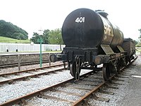 Buffer and chain three-link coupling on a tank wagon
 -
 Balance lever in front of buffer support (balance lever coupling)
 -
 Balance lever behind buffer support (balance lever coupling)
 -
 Electric locomotive of the Furka Oberalp Bahn (today MGB ) with balance lever coupling
 -
 Buffers and chain coupler on goods wagon. The chain hangs on the towing hook.
 -
 Center-buffer-and-chain used on the Royal Railway Cambodia BB 1056 diesel locomotive in Cambodia


See also edit
References edit
- ^ EN 15551:2009+A1:2010 Railway applications – Railway rolling stock – Buffers
- ^ EN 15566-2009+A1:2010 Railway applications – Railway rolling stock – Draw gear and screw coupling
- ^ "WSR :: West Somerset Railway :: Couplings". Archived from the original on 2006-09-26. Retrieved 2006-11-12.
- ^ Green, J. I. T. (November 6, 1964). "Buffer Locking on Reverse Curves". Railway Gazette. 120 – via trid.trb.org.
- ^ Steam Spirit, Vol 1, p 129
- ^ Jane's World Railways 1969-1970 edition
- ^ Railway Gazette International Sept 2012, p 108
External links edit
 Media related to Buffers and chain coupling at Wikimedia Commons