Talk:Common drain
| This is the talk page for discussing improvements to the Common drain article. This is not a forum for general discussion of the article's subject. |
Article policies
|
| Find sources: Google (books · news · scholar · free images · WP refs) · FENS · JSTOR · TWL |
| This article is rated Stub-class on Wikipedia's content assessment scale. It is of interest to the following WikiProjects: | |||||||||||
| |||||||||||

Resistor in the drain lead edit
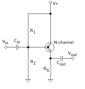
Resistors are not normally used in the drain of common drain amps. Can the author please alter the diagram before reinserting it?Light current 02:40, 7 August 2005 (UTC)
- I'm the author, as you would know if you looked at the image page. The circuit represents the most general case. Set Rd = 0 if you don't want a resistor there. - Omegatron 13:55, August 7, 2005 (UTC)
So you would insert a decoupling cap across a non-existent Drain resistor would you.? Drain resistors are not neccessary,only waste power and limit output voltage swing. This sort of nonsense can only serve to confuse the innocent reader of what is supposed to be a font of ACCURATE knowledge. Can you give a real example (from a TEXT BOOK) of a circuit where a drain resistor is included in a source follower cct?? Light current 19:04, 7 August 2005 (UTC)
- You're not going to get anywhere on the Wikipedia by demanding things or yelling nonsense and "claptrap!" We deal with cranks and know-it-all idiots all the time, and pay no mind to demands or opinion.
- Although transistors are definitely not my strong point and you're probably right, I'm not going to just take your word for it. I'm perfectly willing to remove the cap and resistor from the image, but you'll have to explain your position and convince me with facts that they are never, ever used in real circuits, instead of just saying so angrily.
- The other alternative is to build up a good reputation so people know that they can defer to your superior knowledge, but your attitude and previous edits are not very convincing.
- I originally based my images off of a photocopy of an unknown textbook. They also show the resistor and cap in my copy of Microelectronic circuits, Third Edition, Sedra/Smith, though they seem to have removed them in the fifth edition. Here are two examples in other books: [1], [2] and a web image: [3]- Omegatron 20:22, August 7, 2005 (UTC)
- I refer to Horowitz and Hill's the Art of Electronics, ch3 (Feild Effect Transistors). They cover source followers here and NO resistors are connected in the drain. (2nd ed p133)Light current 01:26, 8 August 2005 (UTC)
What is the DC offset here? edit
Does a source-follower work like an op-amp buffer, or is there a fixed (possibly device-dependent) voltage offset between the gate and source? If so, what values are typical? RichardNeill (talk) 16:03, 28 May 2013 (UTC)
Source follower naming reason edit
The article explains that "In this circuit (NMOS) the gate terminal of the transistor serves as the input, the source is the output, and the drain is common to both (input and output), hence its name".
This doesn't make sense to me. Can somebody explain what is meant by common?
ICE77 (talk) 02:56, 6 August 2015 (UTC)
- "Common" in this context refers to the the "common reference voltage" for signals in this circuit. That is often ground. In other circumstances, the objective of the circuit is to amplify (or operate in some way on) "small" AC signals, and the DC level is unimportant. In that scenario, "common" could be any node that doesn't vary relative to ground, such as the positive supply rail, or an intermediate voltage that's held at a constant voltage by a bypass capacitor. In this circuit the drain is connected to the V+ rail, which performs the function of being a common reference so far as AC signals are concerned. Gwideman (talk) 05:35, 17 December 2015 (UTC)
