Unfolding is a transformation technique of duplicating the functional blocks to increase the throughput of the DSP program in such a way that preserves its functional behavior at its outputs. Unfolding was first proposed by Keshab K. Parhi and David G. Messerschmitt in 1989.[1][2] Unfolding in general program is as known as Loop unrolling.
Unfolding has applications in designing high-speed and low-power ASIC architectures. One application is to unfold the program to reveal hidden concurrency so that the program can be scheduled to a smaller iteration period, thus increasing the throughput of the implementation. Another application is parallel processing in word level or bit level. Therefore these transformed circuit could increase the throughput and decrease the power consumption.
Example edit
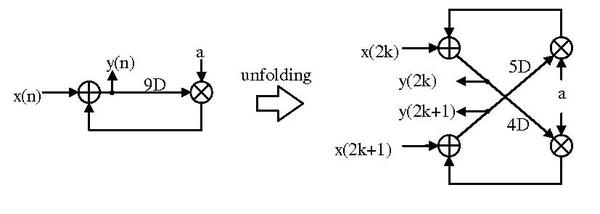
For a DSP program , replacing the index by could result . Similarly, replacing the index by could also result as .


Hence, we transform the program into following program that receives 2 inputs and produce 2 outputs at each time.


Algorithm for unfolding edit
Given a DSP program in Data flow graph(DFG) format and a unfolding factor J, unfolding process transforms the DSP program into a new one by duplicating the functional blocks and reconnecting the functional blocks while maintaining its DSP functionality. We call the program performed with factor J as J-unfolded DFG.
In the J-unfolded DFG, for each node U in original DFG, there are J nodes in the transformed DFG with the same function as U. For each edge in the original DFG, there are J edges in the transformed DFG but its delay is only 1/J times to the original one.
Input format DFG edit
A data flow graph is a labeled directed graph. Each node is labeled by a type indicating its functionality, and each edge is labeled by a number indicating its delay.
Unfolding algorithm edit
Given Unfolding factor J
- For each node U in the original DFG, first, we duplicate the J functional blocks as U0, U1, ..., UJ − 1,
- For each edge U arrow → V with w delays in the original DFG, we create the edges on transformed graph by Ui arrow → V(i+w)%J with for i = 0, 1, ... J − 1.

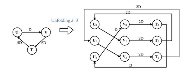
The following graph shows the process of the algorithm. The original DFG is composed of 2 nodes and 1 edge with 37 delays. The unfolding process uses J = 4 as its unfolding factor. The algorithm first duplicates node U and V to 4 U nodes and 4 Vnodes. Then, it perform reconnecting on the nodes with corresponding delays, like U2 connects to V with index (2 + 37)%4 = 3. Besides, the delay on edge U1 to V2 is , and the delay on edge U3 to V0 is .


The following graph is another example showing the unfolding algorithm. Notice that, if there is the delay smaller than unfolding factor J, the J-unfolded DFG would create the edge with 0 delay but whose corresponding edge at original DFG may be the non-zero edge. Therefore, folding process is potential to create the 0-delay edge to increase the longest path in the DFG. ((P.S. fig. of bottom right is T2 that isn't T1))
Properties edit
- Unfolding preserves the number of delay elements in a DFG.
This property holds since the sum of the unfolded DFG is

Hence, transformation could increase J times throughput but the resource in delay element would not increase.
Critical path and retiming edit
When w < J, consider a path with w delays in the original DFG, J-unfolding of this path leads to (J-w) paths with no delays and w path with 1 delay. If all the path on original DFG have the delay larger than J, the critical path of the unfolded DFG is same as the critical path of its original DFG. Hence, the transformed DFG increase its throughput J times. However, if there is a path with delay less than J, it would create a new path without delay. Therefore, the critical path would be potential at such path, that is different as the original critical path, and such that the combinational delay would hence increase. In such case, its throughput would not hence increase J times.
For solving such problem, we could perform retiming on original DFG to let the every path with the delay larger than J.
Unfolding for low power edit
Unfolding is the general case of parallel processing, and it has the low power property same as pipelining and paralleling technique. Although the capacitance would be J times from the original circuit, the time to charge such capacitance is 1/J times. Furthermore, the charging time is inverse-square to its supply voltage. Hence, we could lower the supply voltage to change the J times capacitance in 1/J times time. Eventually, the power consumption is the square to the reduction on supply voltage, and the unfolded circuit could lower its power consumption.
Applications edit
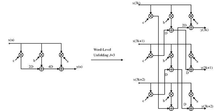
Word-level parallel processing edit
The unfolding transformation could be used to design a word-parallel architecture from a word-serial architecture. The following is the example of word-serial to word-parallel architecture.
Bit-level parallel processing edit
- Bit-serial processing: One bit is processed per clock cycle and a complete word is processed in W clock cycles.
- Bit-parallel processing: One word of W bits is processed every clock cycle.
- Digit-serial processing: N bits processed per clock cycle and a word is processed in W/N clock cycles. The parameter N is referred to as the digit size.
In such way, the unfolding could perform architecture exploration to find a best implementation in a system.

Summary edit
Unfolding transformation can unravel hidden concurrency in digital signal processing systems described by DFGs. Therefore, unfolding can be used to increase the throughput of the system by duplicating the functional blocks but without increasing the delay element. If we properly handle the delay on the path, such as retiming, we could increase the throughput as J times, which is the number of duplication on each functional block. In such transform technique, it could be applied to generate world-parallel architectures that can be used for high-speed or low-power applications. Hence, unfolding is the good technique to leverage between area, throughput, and power-consumption.
See also edit
References edit
- ^ K. K. Parhi and D. G. Messerschmitt,"Fully-static rate-optimal scheduling of iterative data-flow program via optimum unfolding," Proc. of Int'l Conf. on Parallel Processing, 1989, pp. 1-209 – 1-216
- ^ K.K. Parhi, and D.G. Messerschmitt, "Static Rate-Optimal Scheduling of Iterative Data Flow Programs via Optimum Unfolding," IEEE Trans. on Computers, Vol. 40(2), February 1991, pp. 178-195, https://doi.org/10.1109/12.73588