.png)
.png&action=edit&redlink=1)

Size of this preview: 800 × 463 pixels. Other resolutions: 320 × 185 pixels | 640 × 371 pixels | 1,024 × 593 pixels | 1,445 × 837 pixels.
Original file (1,445 × 837 pixels, file size: 176 KB, MIME type: image/png)
| This is a file from the Wikimedia Commons. Information from its description page there is shown below. Commons is a freely licensed media file repository. You can help. |
.png)
Summary
| Description |
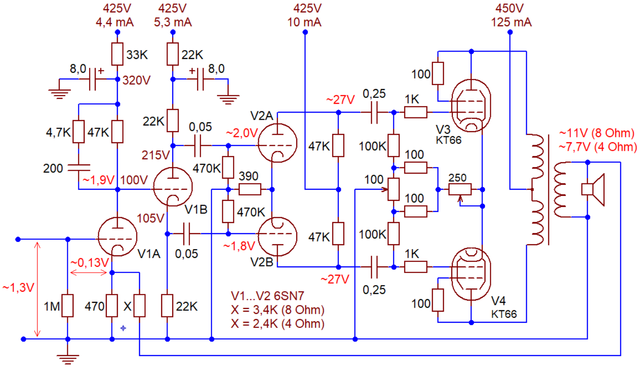
English: The revised Williamson amplifier, as published in the August 1949 Wireless World article. Power supply components omitted. AC voltages, specified by Williamson in peak volts, shown recalculated to effective sine volts. These correspond to 15W output power (as specified by Williamson). The output stage balancing pot (250 Ohm here) was actually a 150 Ohm fixed + 100 Ohm variable. Otherwise it's all original. The X feedback resistor equals 1200*Sqrt(Zoutput) Ohms. |
| Date | |
| Source | Own work (merely a copy of the 1949 circuit by D.T.N.Williamson) |
| Author | Retired electrician |
| This work is ineligible for copyright and therefore in the public domain because it consists entirely of information that is common property and contains no original authorship. |
File history
Click on a date/time to view the file as it appeared at that time.
| Date/Time | Thumbnail | Dimensions | User | Comment | |
|---|---|---|---|---|---|
| current | 17:56, 11 February 2018 | | 1,445 × 837 (176 KB) | Retired electrician | {{Information |Description={{en|The revised Williamson amplifier, as published in the August 1949 ''Wireless World'' article. Power supply components omitted. AC voltages, specified by Williamson in peak volts, shown recalculated to effective sine volt... |
File usage
The following pages on the English Wikipedia use this file (pages on other projects are not listed):
Global file usage
The following other wikis use this file:
- Usage on ru.wikipedia.org
- Usage on www.wikidata.org
.png)